

|
Error code |
Description |
Lamp Check trans |
Control system response |
|
C1312 |
Retarder trigger low voltage |
off |
Retarder does not turn on |
|
C1313 |
Retarder trigger signal high voltage |
off |
Retarder does not turn on |
|
P0122 |
Intermittent or low gas pedal position sensor signal |
off |
Default value is used |
|
P0123 |
High gas pedal position sensor |
off |
Default value is used |
|
P0218 |
Oil temperature is too high |
off |
A control pattern is used in case of temperature |
|
P0562 |
Control unit low voltage |
off |
Prohibition of torque converter lockout. DNA |
|
P0602 |
The control unit is not programmed |
On |
Remains neutral |
|
P0610 |
Error of additional equipment of the car with the control unit |
On |
Uses TID A Calibration Data |
|
P0613 |
Control Unit CPU Error |
off |
All solenoids are off |
|
P0614 |
Incompatibility of ECM and TCM data for engine torque control |
On |
Only neutral, reverse and second gear. Torque lock inhibit, shift adaptation disabled |
|
P0634 |
Control unit temperature exceeded |
On |
DNS , SOL OFF , actively hydraulic control. |
|
P063E |
There is no input signal about the position of the throttle during auto detection |
On |
Default value is used |
|
P063F |
No coolant temperature signal during auto detection |
off |
— |
|
P0657 |
Open circuit HSD1 |
On |
SOL OFF , DNA . Prohibition of torque converter lock, prohibition of main |
|
P0658 |
Low voltage in the HSD circuit 1 |
On |
DNS , SOL OFF , hydraulic control is active |
|
P0659 |
High voltage in the HSD circuit 1 |
On |
DNS , SOL OFF , hydraulic control is active |
|
P0702 |
The control unit did not recognize the automatic transmission configuration |
On |
Uses standard configuration |
|
P0703 |
Malfunction in a chain of the gauge of a brake |
off |
On garbage trucks, the inclusion of N — D is not possible . If the code is active, then |
|
P0708 |
High signal from the current gear sensor. |
On |
Ignores the signal of the strip switch |
|
P070C |
Low oil level sensor signal |
off |
— |
|
P070D |
High oil level sensor signal |
off |
— |
|
P0711 |
Abnormal oil temperature sensor signal |
On |
Uses the default temperature |
|
P0712 |
Low oil temperature sensor signal |
On |
Uses standard temperature |
|
P0713 |
High oil temperature sensor signal |
On |
It uses the standard value tamper Aturi |
|
P0716 |
Turbine wheel speed sensor abnormal signal |
On |
DNS , automatic transmission is blocked on the current transfer |
|
P0717 |
No turbine wheel speed sensor signal |
On |
DNS , automatic transmission is blocked on the current transfer |
|
P0719 |
ABS brake signal low |
off |
Takes ABS off |
|
P071A |
Incompatible RELS Input |
On |
RELS function is disabled |
|
P071D |
Incorrect special function input (wire 101 and 142) |
On |
— |
|
P0721 |
Abnormal output speed sensor signal |
On |
DNS , automatic transmission remains in the current transmission |
|
P0722 |
No output speed sensor signal |
On |
DNS , automatic transmission remains in the current transmission |
|
P0726 |
Abnormal engine speed sensor signal |
off |
Uses standard turbine speed |
|
P0727 |
Missing engine speed sensor signal |
off |
Uses standard turbine speed |
|
P0729 |
6th gear ratio incorrect |
On |
DNS , trying to enable 5th , then 3rd gear |
|
P0731 |
1st gear ratio incorrect |
On |
DNS , trying to enable 2nd, then 5th gear |
|
P0732 |
2nd gear ratio incorrect |
On |
DNS , trying to enable 3rd, then 5th gear |
|
P0733 |
3rd gear ratio incorrect |
On |
DNS , trying to enable 4th, then 6th gear |
|
P0734 |
4th gear ratio incorrect |
On |
DNS , trying to turn on 5th, then 3rd gear |
|
P0735 |
5th gear ratio incorrect |
On |
DNS , trying to turn on the 6th, then 3rd, then 2nd gear |
|
P0736 |
Incorrect gear ratio in reverse gear |
On |
DNS blocked on neutral |
|
P0741 |
Torque converter slip clutch slides |
On |
— |
|
P0752 |
Jamming solenoid SS 1 pressure control valve |
On |
DNS |
|
P0776 |
Malfunction in the hydraulic circuit of the PCS 2 solenoid |
On |
DNS, RPR |
|
P0777 |
Malfunction in the hydraulic circuit of the PCS 2 solenoid |
On |
DNS, RPR |
|
P0796 |
Malfunction in the hydraulic circuit of the PCS 3 solenoid |
On |
DNS, RPR |
|
P0797 |
Malfunction in the hydraulic circuit of the PCS 3 solenoid |
On |
DNS, RPR |
|
P0842 |
PS voltage sensor low voltage 1. |
On |
DNS , automatic transmission remains in the current transmission |
|
P0843 |
Pressure Sensor High Voltage PS 1. |
On |
DNS , automatic transmission remains in the current transmission |
|
P0847 |
PS 2 pressure sensor low voltage |
On |
— |
|
P0848 |
High voltage pressure sensor PS 2 |
On |
— |
|
P0880 |
Power failure of the control unit during engine operation |
off |
— |
|
P0881 |
The voltage at the control unit is too low or is skipping |
off |
— |
|
P0882 |
The voltage at the control unit is below normal. |
On |
DNS , SOL OFF , hydraulic control is active |
|
P0883 |
The voltage on the control unit is above normal |
off |
— |
|
P088A |
Oil filter clogged |
off |
— |
|
P088B |
Oil filter heavily clogged |
off |
— |
|
P0894 |
No torque transmission in first gear |
On |
DNS remains in 1st gear |
|
P0897 |
Gear oil needs to be replaced |
On |
— |
|
P0960 |
Open circuit pressure modulation valve solenoid |
On |
— |
|
P0962 |
Low voltage modulation valve solenoid circuit |
On |
DNS , SOL OFF , hydraulic control active |
|
P0963 |
High voltage in the pressure modulation valve solenoid circuit |
On |
— |
|
P0964 |
PCS2 Solenoid Open Circuit |
On |
DNS , SOL OFF , hydraulic control active |
|
P0966 |
PCS 2 Solenoid Circuit Low Voltage |
On |
DNS , SOL OFF , hydraulic control is active |
|
P0967 |
PCS 2 Solenoid High Voltage |
On |
DNS , SOL OFF , hydraulic control is active |
|
P0968 |
PCS3 Solenoid Open Circuit |
On |
DNS , SOL OFF , hydraulic control is active |
|
P0970 |
PCS 3 Solenoid Circuit Low Voltage |
On |
DNS , SOL OFF , hydraulic control is active |
|
P0971 |
PCS 3 Solenoid Circuit High Voltage |
On |
DNS , SOL OFF , hydraulic control is active |
|
P0973 |
Low voltage in the solenoid circuit SS 1 |
On |
DNS , SOL OFF , hydraulic control is active |
|
P0974 |
High voltage in the solenoid circuit SS 1 |
On |
DNS , SOL OFF , hydraulic control is active |
|
P0975 |
Open circuit solenoid SS2 |
On |
On 7-speed automatic transmissions, 1st and 7th gears are not included |
|
P0976 |
Low voltage in the solenoid circuit SS 2 |
On |
On 7-speed automatic transmissions, 1st and 7th gears are not activated, torque converter lockout |
|
P0977 |
High voltage in the solenoid circuit SS 2 |
On |
On 7-speed automatic transmissions, 1st and 7th gears are not included |
|
P0989 |
The signal from the retarder is intermittent |
off |
Retarder does not turn on |
|
P0990 |
Retarder sensor signal has a short circuit |
off |
Retarder does not turn on |
|
P1739 |
Incorrect gear ratio in low gear |
On |
DNS , prohibition of work in 1 gear |
|
P1891 |
Accelerator pedal position sensor signal below normal |
off |
Uses the standard value for pedal depression |
|
P1892 |
Accelerator Pedal Position Sensor Signal Above Normal |
off |
Uses the standard value for pedal depression |
|
P2184 |
Coolant temperature sensor signal low voltage |
off |
Uses standard temperature |
|
P2185 |
Coolant Temperature Sensor High Voltage |
off |
Uses standard temperature |
|
P2637 |
Malfunction of the torque control system when shifting gears SEM |
On |
Disabling SEM |
|
P2641 |
Violation of the torque limiting system in the lower gears of LRTP |
On |
Disabling LRTP |
|
P2669 |
Open circuit HSD2 |
On |
SOL OFF , torque converter inhibit inhibit, main modulation |
|
P2670 |
HSD 2 low voltage |
On |
DNS , SOL OFF , hydraulic control active |
|
P2671 |
High voltage in the HSD 2 circuit |
On |
DNS , SOL OFF , hydraulic control active |
|
P2684 |
Open circuit HSD3 |
On |
SOL OFF , torque converter inhibit inhibit, main modulation |
|
P2685 |
HSD 3 Low Voltage |
On |
DNS , SOL OFF , hydraulic control is active |
|
P2686 |
HSD 3 High Voltage |
On |
DNS , SOL OFF , hydraulic control is active |
|
P2714 |
Malfunction in the hydraulic circuit of the PCS 4 solenoid |
On |
DNS, RPR |
|
P2715 |
Malfunction in the hydraulic circuit of the PCS 4 solenoid |
On |
DNS , SOL OFF , hydraulic control is active |
|
P2718 |
PCS4 Solenoid Open Circuit |
On |
DNS , SOL OFF , hydraulic control is active |
|
P2720 |
PCS 4 Solenoid Circuit Low Voltage |
On |
DNS , SOL OFF , hydraulic control is active |
|
P2721 |
PCS 4 Solenoid High Voltage |
On |
DNS , SOL OFF , hydraulic control is active |
|
P2723 |
Malfunction in the hydraulic circuit of the PCS 1 solenoid |
On |
DNS, RPR |
|
P2724 |
Malfunction in the hydraulic circuit of the PCS 1 solenoid |
On |
DNS, RPR |
|
P2727 |
PCS1 Solenoid Open Circuit |
On |
DNS , SOL OFF , hydraulic control is active |
|
P2729 |
Low voltage in the PCS 1 solenoid |
On |
DNS , SOL OFF , hydraulic control is active |
|
P2730 |
High voltage in the PCS 1 solenoid |
On |
DNS , SOL OFF , hydraulic control is active |
|
P2736 |
PCS5 Solenoid Open Circuit |
On |
Prohibition of retarder operation |
|
P2738 |
PCS 5 Solenoid Circuit Low Voltage |
On |
Prohibition of work in 1st gear, retarder operation, torque converter lock |
|
P2739 |
PCS 5 Solenoid Circuit High Voltage |
On |
Prohibition of retarder operation |
|
P2740 |
High temperature oil retarders |
off |
— |
|
P2742 |
Retarder oil temperature sensor low signal |
off |
Uses standard oil temperature |
|
P2743 |
Retarder oil temperature sensor high signal |
off |
Uses standard oil temperature |
|
P2761 |
Torque converter solenoid open circuit |
On |
Torque converter lockout |
|
P2763 |
Low voltage in the torque converter lock-up solenoid circuit |
On |
Torque converter lockout |
|
P2764 |
High voltage lock-up torque converter solenoid circuit |
On |
Torque converter lockout |
|
P2789 |
Clutch wear reaches limit value |
On |
— |
|
P278A |
Wrong Kickdown Signal |
off |
Kickdown mode ban |
|
P2793 |
Gear Shift Communication Error |
On |
Ignores PWM control, if the signal through the CAN — bus is also lost, the latter is locked in a selected direction |
|
P2808 |
Malfunction in the hydraulic circuit of the PCS 6 solenoid |
On |
DNS, RPR |
|
P2809 |
Malfunction in the hydraulic circuit of the PCS 6 solenoid |
On |
DNS, RPR |
|
P2812 |
PCS6 Solenoid Open Circuit |
On |
DNS , SOL OFF , hydraulic control is active |
|
P2814 |
PCS 6 Solenoid Circuit Low Voltage |
On |
DNS , SOL OFF , hydraulic control is active |
|
P2815 |
PCS 6 Solenoid Circuit High Voltage |
On |
DNS , SOL OFF , hydraulic control is active |
|
U0001 |
High Speed CAN Bus Counter Overflow ( IESCAN ) |
off |
Uses standard values; disables torque control when shifting gears |
|
U0010 |
CAN Bus Counter Overflow ( IESCAN ) |
off |
Uses standard values; disables torque control when shifting gears |
|
U0100 |
Loss of communication with the engine / power unit ( J 1586) |
On |
Uses default values |
|
U0103 |
Lost Communication With First Gear Shift |
On |
Remains in the selected gear, monitors the signal for changing the direction of movement. The display |
|
U0115 |
Communication error with engine control unit |
On |
Uses standard values, DNA |
|
U0291 |
Communication error with the secondary gear shifter |
On |
Remains in the selected gear, monitors the signal for changing the direction of movement. The display |
|
U0304 |
Primary gear selector not compatible with J 1939 protocol |
On |
DNS blocked in neutral |
|
U0333 |
Secondary switch not compatible with J 1939 protocol |
On |
DNS blocked in neutral |
|
U0400 |
Violation of data transmission protocol J 1939 |
On |
— |
|
U0404 |
Inadequate information from the primary gear shifter |
On |
Remains in the selected gear, monitors the signal for changing the direction of movement. The display |
|
U0442 |
The control unit receives incorrect data from the engine / powertrain control unit included in data bus J 1939 |
off |
— |
|
U0592 |
Inadequate information from the secondary gear shifter |
On |
Remains in the selected gear, monitors the signal for changing the direction of movement. The display |
Table of
fault codes,
Automatic transmission Series 3000, 4000 with electronic control system Gen4
|
Error code |
Description |
Lamp Check Trans |
Control system response |
|
C1312 |
Low voltage signal to turn on the retarder |
OFF |
Retarder does not |
|
C1313 |
High voltage signal to turn on the retarder |
OFF |
Retarder does not |
|
P0122 |
Intermittent or low gas pedal position sensor signal |
OFF |
The default value is used. |
|
P0123 |
High signal level pedal position sensor gas |
OFF |
The default value is used. |
|
P0218 |
Oil temperature too high |
OFF |
A control pattern is used when the temperature is exceeded. Keeps 4 |
|
P0562 |
Low supply voltage control unit |
OFF |
The ban on locking torque converter. DNA |
|
P0602 |
Control unit not programmed |
ON |
Remains neutral |
|
P0610 |
Error of the additional equipment of the car with the control unit |
ON |
TID A calibration data is used. |
|
P0613 |
Control unit processor error |
OFF |
All solenoids are OFF. |
|
P0614 |
Incompatibility of ECM and TCM data to adjust engine torque |
ON |
Only neutral, rear and second gear. Torque lock |
|
P0634 |
Control unit temperature exceeded |
ON |
DNS, SOL OFF, active hydraulic control. |
|
P063E |
No auto throttle |
ON |
The default value is used. |
|
P063f |
No auto coolant |
OFF |
— |
|
P0657 |
HSD1 open circuit |
ON |
SOL OFF, DNA. Interlocking |
|
P0658 |
HSD1 low voltage |
ON |
DNS, SOL OFF, hydraulic control active |
|
P0659 |
HSD1 high voltage |
ON |
DNS, SOL OFF, hydraulic control active |
|
P0702 |
The control unit did not recognize the automatic transmission configuration. |
ON |
Uses standard configuration |
|
P0703 |
Brake Sensor Circuit Malfunction |
OFF |
On the garbage trucks cannot enable ND. If the code |
|
P0708 |
High level signal from the current transmission sensor. |
ON |
Ignore the signal of the strip switch |
|
P070C |
Low oil level sensor signal |
OFF |
— |
|
P070D |
High oil level sensor signal |
OFF |
— |
|
P0711 |
Non-standard oil temperature sensor signal |
ON |
Uses the default temperature |
|
P0712 |
Low oil temperature sensor signal |
ON |
Uses standard temperature value |
|
P0713 |
High oil temperature sensor signal |
ON |
Uses standard temperature value |
|
P0716 |
Non-standard Turbine Wheel Speed Sensor Signal |
ON |
DNS, automatic transmission is blocked on the current transfer |
|
P0717 |
Turbine wheel speed sensor signal missing |
ON |
DNS, automatic transmission is blocked on the current transfer |
|
P0719 |
ABS braking sensor signal low |
OFF |
Considers ABS OFF |
|
P071A |
Incompatible RELS input |
ON |
RELS OFF |
|
P071D |
Wrong input signal of the special function (wire 101 and 142) |
ON |
— |
|
P0721 |
Non-standard output speed sensor signal |
ON |
DNS, automatic transmission remains on the current transfer |
|
P0722 |
No output speed sensor signal |
ON |
DNS, automatic transmission stays on current |
|
P0726 |
Non-standard engine speed sensor signal |
OFF |
Uses standard turbine |
|
P0727 |
Missing engine speed sensor signal |
OFF |
Uses standard turbine |
|
P0729 |
Wrong gear ratio in 6th gear |
ON |
DNS, trying to enable 5th, then 3rd |
|
P0731 |
Incorrect gear ratio in 1st gear |
ON |
DNS, trying to enable 2nd, then 5th |
|
P0732 |
Wrong gear ratio in 2nd gear |
ON |
DNS, trying to enable 3rd, then 5th |
|
P0733 |
Incorrect gear ratio in 3rd gear |
ON |
DNS, trying to enable 4th, then 6th |
|
P0734 |
Incorrect gear ratio in 4th gear |
ON |
DNS, trying to enable 5th, then 3rd |
|
P0735 |
Invalid gear ratio in 5th gear |
ON |
DNS trying to enable 6th then the |
|
P0736 |
Wrong gear ratio in reverse gear |
ON |
DNS blocked on neutral |
|
P0741 |
Slipping clutch locking torque converter |
ON |
— |
|
P0752 |
Stuck solenoid SS1 pressure regulating valve |
ON |
DNS |
|
P0776 |
Malfunction in the PCS2 solenoid hydraulic circuit |
ON |
DNS, RPR |
|
P0777 |
Malfunction in the PCS2 |
ON |
DNS, RPR |
|
P0796 |
Fault in the hydraulic circuit of the PCS3 solenoid |
ON |
DNS, RPR |
|
P0797 |
Fault in the hydraulic circuit of the PCS3 solenoid |
ON |
DNS, RPR |
|
P0842 |
PS1 pressure sensor low voltage. |
ON |
DNS, automatic transmission stays on current |
|
P0843 |
PS1 pressure sensor high voltage. |
ON |
DNS, automatic transmission stays on current |
|
P0847 |
PS2 Pressure Sensor Low Voltage |
ON |
— |
|
P0848 |
PS2 Pressure Sensor High Voltage |
ON |
— |
|
P0880 |
The disappearance of the power control unit during engine operation |
OFF |
— |
|
P0881 |
Control unit voltage too low or jumping |
OFF |
— |
|
P0882 |
The voltage on the control unit is below normal |
ON |
DNS, SOL OFF, hydraulic |
|
P0883 |
The voltage on the control unit is above normal |
OFF |
— |
|
P088A |
Oil filter clogged |
OFF |
— |
|
P088B |
Oil filter heavily clogged |
OFF |
— |
|
P0894 |
No transfer of the moment in first gear |
ON |
DNS remains on 1 transmission |
|
P0897 |
Gear oil requires replacement |
ON |
— |
|
P0960 |
Open circuit solenoid valve modulation pressure |
ON |
— |
|
P0962 |
Low voltage in the solenoid circuit of the pressure modulating valve |
ON |
DNS, SOL OFF, hydraulic |
|
P0963 |
Modulation valve solenoid circuit high voltage pressure |
ON |
— |
|
P0964 |
PCS2 solenoid open circuit |
ON |
DNS, SOL OFF, hydraulic |
|
P0966 |
PCS2 solenoid circuit low voltage |
ON |
DNS, SOL OFF, hydraulic |
|
P0967 |
PCS2 solenoid circuit high voltage |
ON |
DNS, SOL OFF, hydraulic control active |
|
P0968 |
PCS3 solenoid open circuit |
ON |
DNS, SOL OFF, hydraulic control active |
|
P0970 |
PCS3 solenoid circuit low voltage |
ON |
DNS, SOL OFF, hydraulic control active |
|
P0971 |
PCS3 solenoid circuit high voltage |
ON |
DNS, SOL OFF, hydraulic control active |
|
P0973 |
Low voltage in the circuit of the solenoid SS1 |
ON |
DNS, SOL OFF, hydraulic control active |
|
P0974 |
High voltage in the solenoid circuit SS1 |
ON |
DNS, SOL OFF, hydraulic control active |
|
P0975 |
SS2 solenoid open circuit |
ON |
On 7-speed automatic transmissions, 1st and 7th gears are not included. |
|
P0976 |
Low voltage in the solenoid circuit SS2 |
ON |
On 7-speed automatic transmissions, 1st and 7th gears are not included, prohibition of locking the torque converter |
|
P0977 |
High voltage in the solenoid circuit SS2 |
ON |
On 7-speed automatic transmissions, 1st and 7th gears are not included. |
|
P0989 |
The signal from the retarder has |
OFF |
Retarder does not |
|
P0990 |
The signal from the retarder has a short |
OFF |
Retarder does not |
|
P1739 |
Wrong gear ratio in low gear |
ON |
DNS, prohibition of work on 1 transfer |
|
P1891 |
Accelerator pedal position sensor signal below normal |
OFF |
Uses the standard pedal depression value. |
|
P1892 |
Accelerator pedal position sensor signal is above normal |
OFF |
Uses the standard pedal depression value. |
|
P2184 |
Low voltage signal coolant temperature sensor |
OFF |
Uses standard temperature value |
|
P2185 |
Coolant temperature sensor signal high voltage |
OFF |
Uses standard temperature value |
|
P2637 |
Disturbance in the operation of the torque control system when changing gears SEM |
ON |
Prohibition of the SEM system |
|
P2641 |
Disturbance in the system of torque limiting on the lower gears LRTP |
ON |
Disable LRTP system operation |
|
P2669 |
HSD2 open circuit |
ON |
SOL OFF, blocking the torque converter, banning the main modulation, DNA |
|
P2670 |
HSD2 low voltage |
ON |
DNS, SOL OFF, hydraulic control active |
|
P2671 |
HSD2 high voltage |
ON |
DNS, SOL OFF, hydraulic control active |
|
P2684 |
HSD3 open circuit |
ON |
SOL OFF, blocking the torque converter, banning the main modulation, DNA |
|
P2685 |
HSD3 low voltage |
ON |
DNS, SOL OFF, hydraulic control active |
|
P2686 |
HSD3 high voltage |
ON |
DNS, SOL OFF, hydraulic control active |
|
P2714 |
Fault in the hydraulic circuit of the PCS4 solenoid |
ON |
DNS, RPR |
|
P2715 |
Fault in the hydraulic circuit of the PCS4 solenoid |
ON |
DNS, SOL OFF, hydraulic control active |
|
P2718 |
PCS4 solenoid open circuit |
ON |
DNS, SOL OFF, hydraulic control active |
|
P2720 |
PCS4 solenoid circuit low voltage |
ON |
DNS, SOL OFF, hydraulic control active |
|
P2721 |
PCS4 solenoid circuit high voltage |
ON |
DNS, SOL OFF, hydraulic control active |
|
P2723 |
Malfunction in the PCS1 solenoid hydraulic circuit |
ON |
DNS, RPR |
|
P2724 |
Malfunction in the PCS1 solenoid hydraulic circuit |
ON |
DNS, RPR |
|
P2727 |
PCS1 solenoid open circuit |
ON |
DNS, SOL OFF, hydraulic control active |
|
P2729 |
PCS1 solenoid circuit low voltage |
ON |
DNS, SOL OFF, hydraulic control active |
|
P2730 |
PCS1 solenoid circuit high voltage |
ON |
DNS, SOL OFF, hydraulic control active |
|
P2736 |
PCS5 solenoid open circuit |
ON |
The ban on the work of the retarder |
|
P2738 |
PCS5 solenoid circuit low voltage |
ON |
The prohibition of work on the 1st gear, the work of the retarder, |
|
P2739 |
PCS5 solenoid circuit high voltage |
ON |
The ban on the work of the retarder |
|
P2740 |
High oil retarder temperature |
OFF |
— |
|
P2742 |
Low signal level of the retarder oil |
OFF |
Uses standard oil temperature |
|
P2743 |
High signal level of the oil retarder temperature |
OFF |
Uses standard oil temperature |
|
P2761 |
Open circuit solenoid lockout torque converter |
ON |
Prohibition of locking torque converter |
|
P2763 |
Low voltage in the lock-up torque converter solenoid circuit |
ON |
Prohibition of locking torque converter |
|
P2764 |
High voltage in the torque converter lock-up solenoid circuit |
ON |
Prohibition of locking torque converter |
|
P2789 |
Friction clutch wear reaches the limit value |
ON |
— |
|
P278A |
Erroneous signal Kickdown |
OFF |
Kickdown mode ban |
|
P2793 |
Communication error with gear switch |
ON |
Ignores pulse width modulation, if the signal through the CAN bus is also lost, it is blocked in the last direction selected |
|
P2808 |
Fault in the hydraulic circuit of the PCS6 solenoid |
ON |
DNS, RPR |
|
P2809 |
Fault in the hydraulic circuit of the PCS6 solenoid |
ON |
DNS, RPR |
|
P2812 |
PCS6 solenoid open circuit |
ON |
DNS, SOL OFF, hydraulic control active |
|
P2814 |
PCS6 solenoid circuit low voltage |
ON |
DNS, SOL OFF, hydraulic control active |
|
P2815 |
PCS6 solenoid circuit high voltage |
ON |
DNS, SOL OFF, hydraulic control active |
|
U0001 |
High Speed CAN Bus Counter (IESCAN) overflow |
OFF |
Uses standard values, prohibiting the operation of the torque control system when changing gears |
|
U0010 |
CAN Bus Counter Overflow (IESCAN) |
OFF |
Uses standard values, prohibiting the operation of the torque control system when changing gears |
|
U0100 |
Loss of communication with engine / powertrain unit (J1586) |
ON |
Uses standard values |
|
U0103 |
Loss of communication with the first gear selector |
ON |
Remains in the selected gear, monitors the signal to change the direction of movement. The display goes out for 10 seconds, then shows — / — — / — |
|
U0115 |
Communication error with engine control unit |
ON |
Uses standard values, DNA |
|
U0291 |
Communication error with secondary gear selector |
ON |
Remains in the selected gear, monitors the signal to change the direction of movement. The display |
|
U0304 |
Primary gear selector not compatible with J1939 protocol |
ON |
DNS blocked in neutral |
|
U0333 |
Secondary switch not compatible with J1939 protocol |
ON |
DNS blocked in neutral |
|
U0400 |
Violation of data transmission protocol J1939 |
ON |
— |
|
U0404 |
Inadequate information from the primary gear selector |
ON |
Remains in the selected gear, monitors the signal to change the direction of movement. The display goes out for 10 seconds, then shows — / — — / — |
|
U0442 |
The control unit receives incorrect data from the engine / power unit control unit that is included in the J1939 data bus. |
OFF |
— |
|
U0592 |
Inadequate information from the secondary gear selector |
ON |
Remains in the selected gear, monitors the signal to change the direction of movement. The display 10 sec, then shows — / — — / — |
When the control unit recognizes an error of control,
the corresponding error code
is stored in
memory. To save there
are 5 memory cells, the contents of which can be read through the display switch gear. Cells have
names from «d1» to «d5».
Stop the car to read the codes. Ignition must
be on!
·
Read on button switch: Both buttons ↑ ↓ at the same time hold — With engine running
1 time; With the engine running 2 times.
·
Reading on lever switch: Press the button menu — With the engine stopped 1 time; With the engine running 2 times.
The display will show the error code stored in the «d1» field. Codes consist of a letter and a four-digit number. The code in this field will be
displayed until the next field is selected with the Mode button or the reading of codes is completed.
Important note: with active codes, the lamp « Mode ON» lights
up (Red LED on
the mode switching button). Only active
codes lead to blocking of automatic transmission functions.
End reading. To leave
the diagnostic mode,
select the neutral or press the «Menu» button or simultaneously two arrow keys until the display shows «N N «
In case of errors, call the
service center.
CAN (Controller Area Network) — Data bus Network via SAE J1939 protocol for connecting various vehicle systems.
DNA (Do Not Adapt)
— Prohibition of
adaptive mode automatic transmission.
DNS (Do Not Shift) — Prohibition of shifting. Automatic transmission remains on a certain gear and does not respond to commands. Torque converter is not
locked.
ECM (Engine Control Module)
— Engine control
unit.
HSD 1, 2,
… (High Side Driver)
— Power supply
control valves 1, 2, …
LRTP (Low Range Torque Protection) — Engine torque limitation on 1-3 gears.
PCS (Pressure Control Solenoid) — Pressure control solenoid.
RPR (Return to Previous Range)
— Switch to the
previous transfer.
SEM (Shift Energy Management) — Control system of the engine torque M during gear changes.
SOL OFF (Solenoids OFF) All solenoids are electrically disconnected. Until the engine is running, and the oil pump is spinning, movement is possible.
SS (Shift Solenoid)
— Solenoid gear
shift.
TID (Trans ID ) — TCM function to determine the configuration of the automatic transmission and the connected devices.
TCC — Torque
converter lock -up clutch.
TCM — Transmission Control Module
![]()
Allison Transmission 1000/2000 series fault codes
Allison Transmission 1000/2000 series fault codes
Allison Transmission 1000,2000 series fa
Adobe Acrobat Document
1.5 MB
![]()
Shift Selector Operation and Code Manual PDF
Oil level information, diagnostic codes and prognostic features for 3000/4000 Series Allison Transmissions
Allison Transmission Fault Codes Manual
Adobe Acrobat Document
2.3 MB
![]()
Allison Transmission TS3989EN Troubleshooting Manual
3000 and 4000 Product Families Troubleshooting Manual — Allison 4th Generation Controls
Allison Transmission TS3989EN Troublesho
Adobe Acrobat Document
9.6 MB
![]()
Shift Selector 5 Generation Fault Codes Manual PDF
Oil Level Information, Diagnostic Codes and Prognostic Features For 3000/4000 Series™ And Tc10™ Allison Transmissions
Allison Transmission 5th Gen Operation F
Adobe Acrobat Document
489.9 KB
![]()
Allison Transmission 3000/4000 series fault codes
Allison Transmission 3000/4000 series fault codes
Allison Transmission 3000,4000 series fa
Adobe Acrobat Document
318.1 KB
![]()
Allison Transmission Troubleshooting Code Manuals PDF
Allison Transmission Troubleshooting Code Manuals PDF
Allison Transmission TROUBLESHOOTING Cod
Adobe Acrobat Document
711.0 KB
![]()
Shift Selector Operation and Code Manual (MY 09 4th Generation — 4TH GENERATION ELECTRONIC CONTROLS)
Double-digit display and was release after July 2008, equipped with Model Year ’09 prognostics
Shift Selector Operation and Code Manual
Adobe Acrobat Document
664.8 KB
![]()
Allison Transmission 3000/4000 Operator’s Codes Manual PDF
Motorhome Series (MH) Transmissions : 3000 and 4000 Product Families WTEC III Controls and Aliison 4th Generation Controls
Allison Transmission 3000-4000.pdf
Adobe Acrobat Document
2.1 MB
Password: https://www.pdfmanual4trucks.com/
|
Title |
File Size |
Download Links |
|
Allison Transmission 1000 and 2000 Product Families Troubleshooting |
13.1Mb |
Download |
|
Allison Transmission 1000 and 2000 Series Fault Codes List |
18kb |
Download |
|
Allison Transmission 1000,2000 series fault code list [PDF] |
1.5Mb |
Download |
|
Allison Transmission DOC 7.0 PC Service Tools — User Guide PDF |
6.8Mb |
Download |
|
Allison Transmission Electronic Controls Troubleshooting Manual |
54.4Mb |
Download |
|
Allison Transmission TROUBLESHOOTING Codes Manual PDF [PDF] |
713.7kb |
Download |
Password: https://www.pdfmanual4trucks.com/
|
Title |
File Size |
Download Links |
|
Allison 3000-4000 Series Troubleshooting Manual [PDF] |
13.2Mb |
Download |
|
Allison Transmission — Shift Selector — Operator and Diagnostic |
148.3kb |
Download |
|
Allison Transmission 3000,4000 series fault code list [PDF] |
289.6kb |
Download |
|
Allison Transmission 30004000 series fault code list – download PDF |
320.1kb |
Download |
|
Allison Transmission Fault Codes Manual PDF [PDF] |
1.5Mb |
Download |
|
Allison Transmission Troubleshooting Manual GEN4 [PDF] |
2Mb |
Download |
|
Allison Transmission TS2973EN Troubleshooting Manual PDF [PDF] |
5.2Mb |
Download |
|
Shift Selector — Operator and Diagnostic Trouble Code manual |
1.3Mb |
Download |
Коды ошибок акпп аллисон
Основные неисправности и ошибки АКПП
Неправильная эксплуатация, отсутствие техобслуживания или естественное старение — вот причины, почему на панели приборов появляется сигнал «Ошибка АКПП». Водитель может заметить проблему до зажигания лампочки, если распознает признаки неисправности. Расшифровка кодов ошибок поможет узнать в какой цепи произошел сбой, но этого недостаточно для точной диагностики.
Симптомы неисправности АКПП
Водитель может распознать признаки неисправности АКПП тремя способами:
Проблемы DSG схожи по симптомам:
Если индикатор ошибки не гаснет, АКПП не переключается, уходит в аварийный режим, нет движения ни вперед, ни назад — это явный симптом неисправности. Без разборки агрегата не обойтись.
Что поможет избежать типичных неисправностей АКПП
Чтобы не искать способы устранения неисправности коробки автомат в Интернете или в учебниках, лучше заранее узнать, как избежать поломок:
Автоматическая коробка — сложное устройство, созданное по точным инженерным расчётам и конструктивным решениям. Выбирая жидкость и запчасти для АКПП, не стоит жадничать и покупать дешёвые аналоги. Они не выдержат режимов работы автомата, а только отнимут его ресурс.
Основы правильного обследования коробки автомат
Перед тем, как принять решение о ремонте автомата, мастера собирают историю «пациента» и снимают коды ошибок неисправности автоматической коробки передач. Диагностировать АКПП можно по сканеру ELM327. Чтобы самому поставить диагноз, придётся изучить устройство и характерные поломки своей коробки, запастись мануалами.
Коды ошибок помогают найти проблемный участок, но этот метод не даёт точных результатов. Дальше проводят дополнительные исследования:
Если проблема не выявлена, АКПП разбирают для осмотра и проведения тестов:
Разбор АКПП лучше доверить мастеру, знакомому с данной моделью. Однако, не стоит доверять «рентгеновскому» зрению специалиста и заказывать детали до дефектовки и установки диагноза.
Расшифровка кодов системы самодиагностики АКПП
Система бортовой диагностики автоматических коробок OBD-II указывает электроцепи, в которых произошел сбой. Если модуль управления двигателем (ЕСМ) или АКПП (TCM) получил нестандартные показания датчиков, то на бортовой панели загорится индикатор ошибок «Check Engine». Скорость срабатывания лампочки зависит от серьёзности неисправности.
К ошибкам АКПП относятся коды в формате Р07хх и Р08хх. Например, коды P0745 — Р0779 сообщают о проблемах цепи соленоидов. Так, ошибка АКПП группы 0765 — 0769 связана с повреждением соленоида «D», что значит обрыв, замыкание проводки, разрегулировку или поломку клапана. Компьютер выдаёт ошибку, если считывает неверные показания соленоида. Затем управление отключается, а коробка уходит в аварийный режим.
Что означает
Общий код уведомления, может означать:
· повреждение корпуса гидроблока;
Ошибка сообщает об отклонении показателей датчиков от нормы. Чаще всего это связано с неисправностью:
Если при нажатии тормоза не загорается стоп-сигнал, высвечивается ошибка. Возможная причина:
· обрыве или замыкании проводки;
· перегорании предохранителя или лампочек стоп-сигналов;
· неисправности гнезда лампочки;
ЕСМ контролирует обороты двигателя и делится показаниями с ТСМ. Код ошибки срабатывает, если ТСМ не получил сигнал от ЕСМ. Возможные причины:
· повреждение контактов или проводки;
· неправильного уровня масла;
· забитого фильтра, каналов гидроблока;
· неисправных соленоидов или датчиков;
· поломкой одного из модулей управления;
Блокировка ГДТ включается по сигналу ТСМ. Управляющий импульс формируется после сопоставления данных измерителя оборотов двигателя, поступивших от ЕСМ, и измерителя входных оборотов ISS. Ошибка возникает, когда:
· забился или устарел соленоид блокировки ГДТ;
· изношен фрикцион блокировки ГДТ;
· неисправен гидроблок или модуль управления блокировкой ГДТ;
Причины
Определить причину, почему не работает коробка автомат, можно только после сбора основных признаков и расшифровки кодов ошибок. Далее приведены примеры типичных неисправностей АКПП, игнорирование которых может привести к аварии.
Кулиса рычага
Кулиса селектора — связующий механизм между рычагом переключения передач и АКПП. Узел выходит из строя при недостатке смазки, попадании грязи, механической поломке. Неправильная работа механизма может быть связана с разрегулировкой.
Основной признак неисправности кулисы — тугое переключение режимов работы трансмиссии. Если долго не переводить селектор на нижние ступени, то со временем резинки усохнут, а рычаг покроется коррозией.
Появление люфта при качении селектора «влево-вправо» может стать причиной аварий, поскольку мешает чёткому переключению передач. Рычаг АКПП болтается чаще всего из-за разрегулировки, либо ослабления соединения кронштейна троса.
Утечка масла
Падение уровня ATF может стать причиной поломки всей АКПП, поскольку агрегат начинает работать «всухую». Недостаток давления приводит к проскальзыванию фрикционов и некорректному переключению передач. Появляются дёргания, рывки, пробуксовки. Возможные коды ошибок — Р070А — Р070F.
Утечка масла возникает из-за следующих проблем:
Блок управления
Неисправный модуль управления АКПП переводит коробку в аварийный режим: при заведённом двигателе режимы переключаются неправильно или вовсе не реагируют на движение селектора. Электроника выдаёт ошибки U0101, Р0700 — Р0702 и перестаёт работать по следующим причинам:
Проблемы с ТСМ АКПП могут произойти после неудачной перепрошивки, поэтому программирование лучше доверять сервис-центрам.
Неисправности гидроблока
Признаки неисправности гидроблока АКПП: удары и толчки при переключении передач, пробуксовка «на горячую». В запущенном случае может произойти масляное голодание, перегрев, ухудшение динамики автомобиля. Возможные коды ошибок — Р0700 — Р0702, Р0729 — P0736, и другие ошибки, указывающие на проблемы с соленоидами.
Неисправности и ошибки гидроблока АКПП появляются из-за старого масла и высоких нагрузок:
Корзина сцепления
Сцепление в роботе «выключает» крутящий момент, чтобы коробка безопасно переключила передачу. Частая проблема узла — пробуксовка. Это может значить, что:
Если во время движения автомобиль встаёт в аварийный режим, и нет движения ни вперёд, ни назад, нужно проверить выжимной подшипник и его направляющую. Разбитая от высоких нагрузок деталь приводит к поломке всей корзины, «сгрызая» нажимные лепестки. Понять, что АКПП умирает, можно по переключению рычага: сначала будет трудно включить определённую передачу, а когда коробка умрёт — невозможно.
Хруст при включении передней или задней передачи указывает, что сцепление срабатывает не до конца. Проблема может скрываться в актуаторе, выжимном подшипнике или деформированном диске сцепления. Возможный код ошибки — Р0810 — Р0813.
Неисправность гидротрансформатора
Неисправность гидротрансформатора АКПП проявляется в виде стука, шуршания, вибраций, плохой динамики, повышенного расхода топлива. Автомобиль будет двигаться с трудом и медленно набирать скорость. Если агрегат полностью вышел из строя, то машина будет глохнуть или не сдвинется с места. Возможные коды ошибок — Р0740 — Р0744.
Гидромуфта коробки автомат не работает и выдаёт ошибки по следующим причинам:
«Бублик» — главный загрязнитель и нагреватель масла АКПП. Ухудшение свойств жидкости приводит к падению давления, перегреву коробки. Жидкость может нагреваться до 120 — 150℃, «сжигая» детали автомата. Чтобы снизить нагрузку на гидротрансформатор, устанавливают дополнительные радиаторы охлаждения ATF.
Тормозная муфта
Тормозная муфта плавно фиксирует планетарный механизм автомата. Износ тормозной ленты становится причиной появления толчков, рывков и других неприятностей при переключении передач. Если машина буксует на месте, или не работает одна из передач, возможно, произошёл обрыв манжет поршня тормозной ленты.
Тормозная муфта не срабатывает в АКПП обычно при огромном пробеге, в простых коробках, типа Toyota А131Л, VW 010, Chrysler 31TH, ленту меняют в совсем изношенном состоянии. К этому времени муфта полностью пропитывается горелым маслом и клеевыми смолами от «съеденных» фрикционов.
Возможные коды ошибок Р0729 — P0736.
Профилактика неисправностей
Неисправности АКПП появляются из-за грязного масла и агрессивного вождения, способы их устранения заключаются в ремонте и замене деталей. Для профилактики заболеваний коробки нужно:
Заключение
Поломки АКПП приводят к сложному и дорогому ремонту. По справочникам неисправностей редко кто может «вылечить» агрегат, поэтому приходится обращаться в сервис. Предотвратить внеплановый ремонт АКПП поможет плановое техобслуживание и бережное отношение к автомобилю.
Код ошибки P2714 – электромагнитный клапан «D» управления давлением АКПП заклинил в выключенном состоянии
Код ошибки P2714 звучит как «электромагнитный клапан «D» управления давлением АКПП заклинил в выключенном состоянии». Часто, в программах, работающих со сканером OBD-2, название может иметь английское написание «Pressure Control Solenoid “D” Performance Or Stuck Off».
Техническое описание и расшифровка ошибки P2714
Этот диагностический код неисправности (DTC) является общим кодом трансмиссии. Ошибка P2714 считается общим кодом, поскольку применяется ко всем маркам и моделям транспортных средств. Хотя конкретные этапы ремонта могут несколько отличаться в зависимости от модели.
Код неисправности P2714 OBD-II устанавливается, когда модуль управления (PCM) обнаружил проблему с электромагнитным клапаном управления давлением трансмиссии «D». Большинство автоматических трансмиссий имеют по крайней мере три клапана, которые обозначаются A, B и C.
Набор кодов основан на конкретной неисправности, которая предупреждает PCM и включает контрольную лампу двигателя.
Электромагнитные клапаны регулировки давления в трансмиссии служат для управления давлением жидкости и правильной работы АКПП. PCM получает электронный сигнал, основанный на давлении внутри электромагнитного клапана. Автоматическая трансмиссия управляется лентами и муфтами, которые переключают передачи, оказывая давление жидкости в нужном месте в нужное время.
На основе сигналов от связанных устройств, контролирующих скорость транспортного средства, PCM управляет электромагнитными клапанами давления. Чтобы направлять жидкость с соответствующим давлением в различные гидравлические контуры. Которые изменяют передаточное число трансмиссии в нужное время.
Код P2714 устанавливается PCM, когда электромагнитный клапан управления давлением «D» не работает должным образом или застрял в положении «Выкл.».
Симптомы неисправности
Основным симптомом появления ошибки P2714 для водителя является подсветка MIL (индикатор неисправности). Также его называют Check engine или просто «горит чек».
Также они могут проявляться как:
Серьезность этого кода обычно умеренная, но может быстро перейти на более серьезный уровень, если не исправить своевременно.
Причины возникновения ошибки
Код P2714 может означать, что произошла одна или несколько следующих проблем:
Как устранить или сбросить код неисправности P2714
Некоторые предлагаемые шаги для устранения неполадок и исправления кода ошибки P2714:
Диагностика проблем
Перед тем, как начать процесс поиска и устранения любой неисправности, вам следует изучить бюллетени технического обслуживания (TSB) для конкретного автомобиля. В некоторых случаях это может сэкономить много времени, указав вам правильное направление.
Далее, необходимо проверить уровень жидкости и проверить ее состояние на предмет загрязнения. Перед заменой жидкости вам следует проверить записи транспортного средства, чтобы узнать, когда в последний раз меняли фильтр и жидкость.
После этого следует произвести подробный визуальный осмотр для проверки состояния проводки на предмет явных дефектов. Проверьте разъемы и проводку к электромагнитному клапану управления давлением трансмиссии, насосу трансмиссии и PCM. В зависимости от конфигурации, трансмиссионный насос может иметь электрический или механический привод.
Нормальные показания для проводки и соединений должны составлять 0 Ом сопротивления. Проверка целостности проводки всегда должна выполняться при отключенном питании от цепи. Чтобы избежать короткого замыкания и создания дополнительных повреждений.
Сопротивление или отсутствие целостности указывают на неисправную проводку, которая разомкнута или закорочена. В этом случае потребуется ремонт или замена.
На каких автомобилях чаще встречается данная проблема
Проблема с кодом P2714 может встречаться на различных машинах, но всегда есть статистика, на каких марках эта ошибка присутствует чаще. Вот список некоторых из них:
С кодом неисправности Р2714 иногда можно встретить и другие ошибки. Наиболее часто встречаются следующие: P0500, P0504, P0571, P0573, P0700, P0722, P0741, P0746, P0751, P0761, P0776, P0796, P0842, P0873, P0894, P0983, P1589, P2713, P2715, P2716, P2717, C1241, U660E.
Источник
Allison Transmission GEN4 Troubleshooting Manual
![]()
Автоматические коробки передач
Allison 3000 и 4000 Серии
с электронным управлением Gen4.
Руководство по эксплуатации и обслуживанию
АКПП Allison 3000 и 4000 cерий
Электронное управление Gen4.
Походный проезд, д. 4, стр. 1, 2 этаж, офис 207.
E-mail: allison@ndgs.ru или moscow@ndgs.ru

Автоматические коробки передач
Allison 3000 и 4000 Серии
с электронным управлением Gen4.
0. Условия использования руководства и ограничение ответственности.
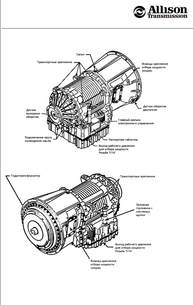
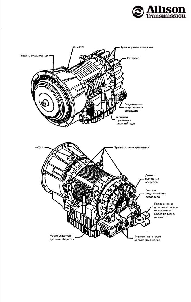
1.0.2 Вид АКПП 3000 Серии с ретардером.
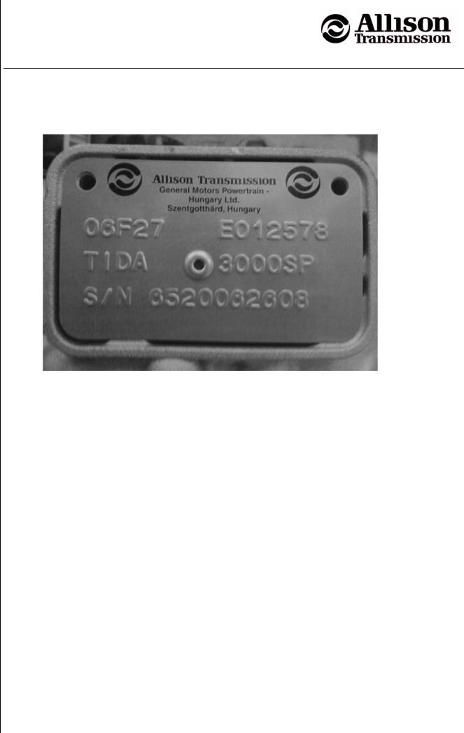
1.0.3 Паспортная табличка АКПП.
1.1 Электронная система управления.
2.0.1 Общие указания по эксплуатации.
2.1.1 Элементы переключателя передач.
2.1.1.3 Светодиод включения дополнительного режима.
2.1.1.4 Кнопка меню (только для рычажного переключателя).
2.1.2 Выбор режима кнопочным переключателем.
2.1.3 Положения рычажного переключателя.
2.2 Другие элементы управления и контроля.
2.2.1 Контрольная лампа нарушения нормальной работы «Check Trans».
2.2.2 Контрольная лампа температуры масла АКПП.
2.2.3 Указатель температуры масла АКПП.
2.2.4 Управление ретардером (опция).
2.2.4.1 Аккумулятор ретардера.
2.3.1 Порядок переключения передач.
2.3.3 Торможение двигателем.
2.3.4 Торможение ретардером.
2.3.5 Предохранительные функции.
2.3.5.1 Защита от перекрутки двигателя и включения слишком низкой
2.3.5.2 Блокировка включения передачи.
2.3.5.3 Влияние температуры масла АКПП и ретардера на
2.3.6 Дополнительные функции.
2.3.6.1 «Быстрая нейтраль» для мусоровозов.
2.3.6.2 Блокировка движения для пожарных машин и спецтехники.
2.3.6.3 Выходной сигнал скорости.
2.4 Меры при буксировке автомобиля.
2.4.1 Запуск двигателя буксировкой.
2.4.2 Буксировка с выключенным двигателем.
2.5.1 Считывание кодов ошибок.
Руководство по эксплуатации и обслуживанию Allison 3000/4000 Gen4.

Автоматические коробки передач
Allison 3000 и 4000 Серии
с электронным управлением Gen4.
3.1.1 Проверка уровня масла посредством масляного щупа.
3.1.2 Проверка уровня масла через переключатель передач.
Периоды замены масла и фильтров .
Краткая информация по маслам.
4.1 Считывание кодов ошибок.
Руководство по эксплуатации и обслуживанию Allison 3000/4000 Gen4.

Автоматические коробки передач
Allison 3000 и 4000 Серии
с электронным управлением Gen4.
0. Условия использования руководства и ограничение ответственности
Представленный печатный документ и приводимая в нем информация служат как базисный материал для курсов обучения в НДГС и DGS Diesel- &Getriebeservice GmbH.
Целью обучения является ознакомление с конструкцией и возможностями охватываемых руководством АКПП. Приводимая информация не претендует на полноту и не подлежит автоматическому обновлению при внесении изменений в конструкцию. Учет изменений производится только при переработке издания автором.
Самую последнюю информацию можно найти в соответствующих публикациях Allison Transmission. В разделе литература представлен список изданий Allison Transmission.
Также можно зайти на сайт www.allisontransmission.com
ООО «НДГС», DGS Diesel- &Getriebeservice GmbH и Allison Transmission не несут ответственности за любой ущерб, возникший от использования данного руководства.
Содержимое данного издания и приводимая информация защищены авторскими правами. Копирование, распространение и частичное или полное воспроизведение без письменного разрешения DGS или Allison Transmission не допускаются.
Руководство по эксплуатации и обслуживанию Allison 3000/4000 Gen4.

Автоматические коробки передач
Allison 3000 и 4000 Серии
с электронным управлением Gen4.
Автоматические трансмиссии Allison 3000 и 4000 Серии – полностью автоматические коробки передач, использующие самые современные технологии с электронной системой управления с шестью (или семью) передачами вперед и одной назад.
Приведенные параметры зависят от применения АКПП (типа транспортного средства). Чтобы получить точные спецификации, обратитесь в ООО «НДГС» или зайдите на сайты www.ndgs.ru или www.allisontransmission.com
Для всех серий имеются различные модификации:
Модификация с возможностью установки КОМ.
Все модельные ряды построены по общему принципу:
На входе АКПП стоит гидротрансформатор с функцией блокирования (Lock-Up) и встроенным демпфером крутильных колебаний.
После гидротрансформатора следуют косозубые планетарные ряды, организованные по запатентованной схеме, позволяющие плавно переключать передачи без разрыва потока мощности.
Автоматическое переключение управляется электронной системой на основе следующих входных данных:
Положение переключателя передач – Информация о выбранном водителем режиме
Частота вращения выходного вала – Информация о скорости автомобиля
Положение педали акселератора – Информация о режиме работы двигателя
На АКПП может быть установлено до двух отборов мощности
На выходе может быть установлен ретардер
Руководство по эксплуатации и обслуживанию Allison 3000/4000 Gen4.
Автоматические коробки передач
Allison 3000 и 4000 Серии
с электронным управлением Gen4.
Руководство по эксплуатации и обслуживанию Allison 3000/4000 Gen4.
Автоматические коробки передач
Allison 3000 и 4000 Серии
с электронным управлением Gen4.
1.0.2 Вид АКПП 3000 Серии с ретардером
Руководство по эксплуатации и обслуживанию Allison 3000/4000 Gen4.
Автоматические коробки передач
Allison 3000 и 4000 Серии
с электронным управлением Gen4.
При заказе запасных частей или при решении технических вопросов, а также при проведении гарантийного ремонта, потребуется серийный номер АКПП.
На паспортной табличке можно найти следующую информацию:
Производитель и завод-производитель
Идентификационный номер АКПП Allison
Идентификационный код АКПП
10-значный серийный номер АКПП
1.1 Электронная система управления
С 2005 модельного года АКПП 3000 и 4000 Серии оснащаются электронной системой управления Allison 4-го поколения (сокращенно Gen4).
Постоянные улучшения и расширения возможностей системы позволяют добавлять новые функции.
Система состоит из следующих компонентов:
Блок управления АКПП (TCM=»Transmission Control Module»);
Три датчика частоты вращения: коленвала двигателя, турбины, выходного вала
Электронный переключатель передач;
Руководство по эксплуатации и обслуживанию Allison 3000/4000 Gen4.

Автоматические коробки передач
Allison 3000 и 4000 Серии
с электронным управлением Gen4.
Электрогидравлический блок управляющих клапанов.
Блок управления обрабатывает информацию различных датчиков, а также информацию от других систем автомобиля и подаёт сигналы на электромагнитные клапаны для переключения передач.
Блок управления отслеживает скорости вращения выходного вала, коленвала двигателя и турбинного колеса, а также температуру и давление масла. При нарушении нормальной работы в памяти TCM сохраняются коды ошибок, которые можно считать с дисплея переключателя передач.
Электронная система управления отвечает также за отбор мощности, ретардер и другие функции такие, как торможение двигателем, защита от превышения оборотов, блокировка включения передач, «быстрая нейтраль».
Электронная система управления Gen4 совместима с протоколом связи CAN и может обмениваться информацией с другими системам автомобиля.
Руководство по эксплуатации и обслуживанию Allison 3000/4000 Gen4.

Автоматические коробки передач
Allison 3000 и 4000 Серии
с электронным управлением Gen4.
2.0.1 Общие указания по эксплуатации
Почему полностью автоматическая трансмиссия?
На Вашем автомобиле установлена АКПП Allison 3000/4000 Серии. Эта полностью автоматическая трансмиссия с электронным управлением, использующая самые современные технологии, облегчает управление Вашим коммерческим транспортным средством в тяжелых уличных условиях. В особенности при коротких перевозках в режиме частых остановок автоматическая трансмиссия оказывается оптимальной.
АКПП имеет в зависимости от конструкции и программы управления 4, 5, 6 или 7 передач вперед и 1 назад.
В качестве муфты включения и отключения АКПП служит гидротрансформатор со встроенным механизмом блокировки, который автоматически блокирует гидротрансформатор в движении и разблокирует при остановках. Гидротрансформатор обеспечивает высокий крутящий момент и плавность при трогании, а механизм блокировки
АКПП спроектирована для удобного обслуживания. Ознакомьтесь, пожалуйста, с руководством по техническому обслуживанию.
Для оптимального переключения передач и повышения срока жизни АКПП, всегда следите за следующим:
Несколько советов (базовых правил) по эксплуатации АКПП
Перемену направления движения производить только при остановке автомобиля
и холостых оборотах двигателя.
Используйте стояночный тормоз только при холостых оборотах двигателя.
Следите за тем, чтобы в режиме Drive ручной газ и повышение оборотов
Не допускайте движения автомобиля на нейтральной передаче
На светофоре или в аналогичных ситуациях не выключайте передачу.
Включайте нейтраль только при остановках более 5 минут.
Не допускайте работу двигателя более 5 минут при стоянке автомобиля и
Если вы покидаете автомобиль, включайте нейтраль.
Следите за уровнем масла в АКПП
Соблюдайте периоды обслуживания
Руководство по эксплуатации и обслуживанию Allison 3000/4000 Gen4.
![]()
Автоматические коробки передач
Allison 3000 и 4000 Серии
с электронным управлением Gen4.
Переключатель передач может быть выполнен в виде кнопочной панели или рычага. Оба варианта электронные.
Как специальный вариант есть упрощенные кнопочные панели. Эти панели сохраняют все функции управления, однако на них отсутствует возможность диагностики и проверки уровня масла, поскольку отсутствует дисплей.
2.1.1 Элементы переключателя передач
Переключатель передач имеет двухэлементный цифровой дисплей
Во время нормальной работы на дисплее отображается два значения. Слева отображается высшая достигаемая передача. В нормальных условиях она определяется положением рычага переключателя передач или задается кнопочным переключателем. Справа на дисплее отображается текущая передача.
При активировании дополнительной функции АКПП может автоматически выбирать передачу, отличающуюся от выбранной водителем. Так, например, при торможении двигателем включается 2-ая передача.
При включении некоторых функций, а также для защиты АКПП в некоторых случаях может быть заблокировано включение передачи. В этом случае независимо от выбора передачи справа будет показана нейтральная передача N. Для снятия блокировки требуется выключить дополнительные функции или устранить причину блокировки.
Показания при нарушении работы
Если жидкокристаллический дисплей полностью высвечен более 12 секунд, это означает, что ему не удалось подключиться к системе управления. Выключите зажигание и включите снова.
Руководство по эксплуатации и обслуживанию Allison 3000/4000 Gen4.

Автоматические коробки передач
Allison 3000 и 4000 Серии
с электронным управлением Gen4.
Если дисплей не горит и в обоих полях через 10 сек. появляются прочерки, подключение к блоку управления нарушено или имеется код ошибки.
Если дисплей не горит вообще, проверьте его подключение.
При ошибках, включающих диагностическую лампу «Check Trans», в поле выбранной передачи ничего не горит, а справа отображается текущая передача.
Если при движении возникает критическая ошибка, управление не реагирует на выбранную передачу, и АКПП остается на включенной в текущий момент передаче, пока двигатель не будет остановлен и зажигание выключено. После этого в случае критической ошибки АКПП будет оставаться в нейтрали, пока не будет устранена причина ошибки.
Показания в режиме диагностики
В режиме проверки уровня масла будет показан код уровня масла.
В режиме диагностики отображаются сохраненные (прошлые) и текущие (активные) коды ошибок.
(«Mode» = Режим) Кнопка режима Mode выполняет две функции:
Кнопкой режима включается запрограммированная дополнительная функция. Для контроля включения режима загорается светодиод. В большинстве случаев дополнительный режим — это особый (например, экономичный) режим переключения передач.
Примеры дополнительных режимов:
«Динамика» — переключение происходит на высоких оборотах двигателя, используется вся его мощность
«Экономия» — двигатель работает в пределах оборотов обеспечивающих наибольшую экономичность.
В режиме диагностики ошибок кнопка Mode переключает сохраненные коды ошибок
2.1.1.3 Светодиод включения дополнительного режима
На кнопке Mode находится красный светодиод. Включение этого диода может означать две вещи:
При нормальной работе это означает, что включен второй режим.
В режиме диагностики, — что отображаемый код ошибки является активным (причина ошибки не устранена)
2.1.1.4 Кнопка меню (только для рычажного переключателя)
Проверка уровня масла и диагностика
Проверка уровня масла (нажать 1 раз)
Диагностика (нажать 2 раза)
При кнопочном переключателе эти функции вызываются соответствующим нажатием
одновременно двух стрелочных кнопок.
Руководство по эксплуатации и обслуживанию Allison 3000/4000 Gen4.
Источник
![]()
![]()
Allison Transmission 1000 — 2000 Fault Codes DTC
Allison Transmission 1000 — 2000 Fault Codes DTC
Allison Transmission 1000 — 2000 Fault C
Adobe Acrobat Document
19.7 KB
ALLISON 1000, 2000 & 24000 Transmission Fault Codes DTC
DTC Description
Check
Trans
Light Page
P0121 Pedal Postion Sensor Performance Problem No 5-15
P0122 Pedal Postion Sensor Circuit Low Voltage No 5-16
P0123 Pedal Postion Sensor Circuit High Voltage No 5-19
P0218 Transmission Fluid Over Temperature No 5-22
P0562 System Voltage Low Yes 5-26
P0563 System Voltage High Yes 5-29
P0602 TCM Not Programmed Yes 5-33
P0606 Controller Internal Performance Yes 5-34
P0701 Transmission Control System Performance No 5-35
P0703 Brake Switch Circuit No 5-37
P0705 Transmission Range Sensor Circuit (PRNDL Input) No 5-41
P0706 Transmission Range Sensor Circuit Performance Yes 5-45
P0708 Transmission Range Sensor Circuit High Input Yes 5-49
P0710 Transmission Fluid Temperature Sensor Malfunction No 5-53
P0711 Transmission Fluid Temperature Sensor Circuit Performance Yes 5-57
P0712 Transmission Fluid Temperature Sensor Circuit Low Input (High Temperature) Yes 5-61
P0713 Transmission Fluid Temperature Sensor Circuit Low Input (Low Temperature) Yes 5-65
P0716 Turbine Speed Sensor Circuit Performance Yes 5-69
P0717 Turbine Speed Sensor Circuit No Signal Yes 5-73
P0721 Output Speed Sensor Circuit Performance Yes 5-77
P0722 Output Speed Sensor Circuit No Signal Yes 5-81
P0726 Engine Speed Input Circuit Performance Yes 5-85
P0727 Engine Speed Sensor Circuit No Signal Yes 5-89
P0731 Incorrect 1st Gear Ratio Yes 5-93
P0732 Incorrect 2nd Gear Ratio Yes 5-97
P0733 Incorrect 3rd Gear Ratio Yes 5-101
P0734 Incorrect 4th Gear Ratio Yes 5-105
P0735 Incorrect 5th Gear Ratio Yes 5-109
P0736 Incorrect Reverse Ratio Yes 5-113
P0741 Torque Converter Clutch System Stuck Off Yes 5-117
P0742 Torque Converter Clutch System Stuck On Yes 5-120
P0748 Pressure Control Solenoid A Electrical Yes 5-123
P0763 Shift Solenoid C Electrical Yes 5-127
P0768 Shift Solenoid D Electrical Yes 5-131
P0773 Shift Solenoid E Electrical Yes 5-135
P0778 Pressure Control Solenoid B Electrical Yes 5-139
P0840 Transmission Pressure Switch Solenoid C Circuit Yes 5-143
P0841 Transmission Pressure Switch Solenoid C Circuit Stuck Open Yes 5-147
P0842 Transmission Pressure Switch Solenoid C Circuit Stuck Closed Yes 5-151
P0843 Transmission Pressure Switch Solenoid C Circuit High Yes 5-155
P0845 Transmission Pressure Switch Solenoid D Circuit Yes 5-159
P0846 Transmission Pressure Switch Solenoid D Circuit Yes 5-163
P0847 Transmission Pressure Swtich Solenoid D Circuit Yes 5-167
P0848 Transmission Pressure Switch Solenoid D Circuit Yes 5-171
P1688 Unmanaged Engine Torque Delivered to TCM Yes 5-175
P1709 Transmission Pressure Switch Solenoid E Circuit Yes 5-177
P1710 Transmission Pressure Switch Solenoid E Circuit Stuck Open Yes 5-181
P1711 Transmission Pressure Switch Solenoid E Circuit Stuck Closed Yes 5-185
P1712 Transmission Pressure Switch Solenoid E Circuit High Yes 5-189
P1713 Transmission Pressure Switch Reverse Circuit Yes 5-193
P1714 Transmission Pressure Switch Reverse Circuit Stuck On Yes 5-197
P1716 Transmission Pressure Switch Reverse Circuit High no 5-201
P1718 Incorrect Neutral Gear Ration No 5-205
P1720 Solenoid A Controlled Clutch Not Engaged Yes 5-209
P1721 Solenoid B Controlled Clutch Not Engaged Yes 5-213
P1723 Solenoid A Controlled Clutch Engaged Yes 5-217
P1724 Solenoid B Controlled Clutch Engaged Yes 5-221
P1726 Shift Solenoid D Controlled Clutch Engaged No 5-225
P1727 Shift Controlled E Clutch Engaged No 5-229
P1760 TCM Supply Voltage No 5-233
P1779 Engine Torque Delivered To ECM Yes 5-236
P1835 Kickdown Circuit Yes 5-238
P1860 Torque Converter Clutch PWM Solenoid Circuit —Electrical Yes 5-241
P1875 4WD Low Switch Circuit Yes 5-245
P1891 Throttle Postion Sensor Pulse Width Modulation (PWM) Signal Low Input No 5-249
P1892 Throttle Postion Sensor Pulse Width Modulation (PWM) Signal High Input No 5-252
U1000 Serial Data Communication Link Malfunction (Class2) No* 5-255
U1016 Class 2 Powertrain Controller State of Health Failure No* 5-258
U1041 Class 2 ABS Controller State of Health Failure No* 5-261
U1064 Class 2 TBC Controller State of Health Failure No* 5-264
U1096 Class 2 IPC Controller State of Health Failure No* 5-267
U1300 Serial Data Communication Link Low (Class2) No 5-270
U1301 Serial Data Communication Link High (Class2) No 5-273
U2104 Can Bus Rest Counter Overrun Yes 5-276
U2105 Can Bus Error ECM Yes 5-279
Симптомы неисправности АКПП
- горит индикатор неисправности трансмиссии (шестеренка с восклицательным знаком)
- некорректное переключение передач (“пинается”, медленно переключается)
- не включается какая-либо передача (автомобиль не начинает движение)
- трансмиссия перешла в “аварийной режим”
- автомобиль глохнет из-за смены скорости
- работает только 3-я передача
- трансмиссия издает разные звуки (воет, гудит)
- движение автомобиля происходит при установленном рычаге в позицию “N”
- горит индикатор неисправности CHECK ENGINE
Коды ошибок АКПП
P0700 – Управление АКПП, запрос неисправностей (MIL) — неисправность электрической цепи
P0701 – Система управления АКПП — диапазон/функционирование
P0702 – Система управления АКПП — электрическая неисправность
P0703 – Выключатель стоп-сигналов B — неисправность электрической цепи
P0704 – Концевой выключатель (датчик положения) педали сцепления — неисправность электрической цепи
P0705 – Датчик положения селектора АКПП, входной сигнал PRNDL — неисправность электрической цепи
P0706 – Датчик положения селектора КПП — диапазон/функционирование
P0707 – Датчик положения селектора АКПП — низкий уровень сигнала
P0708 – Датчик положения селектора АКПП — высокий уровень входного сигнала
P0709 – Датчик положения селектора АКПП — ненадежный контакт электрической цепи
P0710 – Датчик температуры рабочей жидкости АКПП — неисправность электрической цепи
P0711 – Датчик температуры рабочей жидкости КПП — диапазон/функционирование
P0712 – Датчик температуры рабочей жидкости КПП — низкий уровень сигнала
P0713 – Датчик температуры рабочей жидкости КПП — высокий уровень входного сигнала
P0714 – Датчик температуры рабочей жидкости КПП — ненадежный контакт электрической цепи
P0715 – Датчик частоты вращения входного вала АКПП (турбины гидротрансформатора) — неисправность электрической цепи
P0716 – Датчик частоты вращения входного вала АКПП (турбины гидротрансформатора) — диапазон/функционирование
P0717 – Датчик частоты вращения входного вала АКПП (турбины гидротрансформатора) — нет сигнала
P0718 – Датчик частоты вращения входного вала АКПП (турбины гидротрансформатора) — ненадежный контакт электрической цепи
P0719 – Выключатель стоп-сигналов B — низкий уровень сигнала
P0720 – Датчик частоты вращения выходного вала — неисправность электрической цепи
P0721 – Датчик частоты вращения выходного вала — диапазон/функционирование
P0722 – Датчик частоты вращения выходного вала — нет сигнала
P0723 – Датчик частоты вращения выходного вала — ненадежный контакт электрической цепи
P0724 – Выключатель стоп-сигналов B — высокий уровень сигнала
P0725 – Частота вращения коленчатого вала, входной сигнал — неисправность электрической цепи
P0726 – Частота вращения коленчатого вала, входной сигнал — диапазон/функционирование
P0727 – Частота вращения коленчатого вала, входной сигнал — нет сигнала
P0728 – Частота вращения коленчатого вала, входной сигнал — ненадежный контакт электрической цепи
P0729 – 6-я передача — некорректное передаточное отношение
P0730 – Некорректное передаточное отношение
P0731 – 1-я передача — некорректное передаточное отношение
P0732 – 2-я передача — некорректное передаточное отношение
P0733 – 3-я передача — некорректное передаточное отношение
P0734 – 4-я передача — некорректное передаточное отношение
P0735 – 5-я передача — некорректное передаточное отношение
P0736 – Передача заднего хода — некорректное передаточное отношение
P0737 – Электронный блок управления АКПП, частота вращения — выходная цепь
P0738 – Электронный блок управления АКПП, частота вращения — низкий уровень выходного сигнала
P0739 – Электронный блок управления АКПП, частота вращения — высокий уровень выходного сигнала
P0740 – Электромагнитный клапан муфты блокировки гидротрансформатора — неисправность электрической цепи
P0741 – Электромагнитный клапан муфты блокировки гидротрансформатора — функционирование или «залипание» в закрытом состоянии
P0742 – Электромагнитный клапан муфты блокировки гидротрансформатора — «залипание» в открытом состоянии
P0743 – Электромагнитный клапан муфты блокировки гидротрансформатора — электрическая неисправность
P0744 – Электромагнитный клапан муфты блокировки гидротрансформатора — ненадежный контакт электрической цепи
P0745 – Электромагнитный клапан управления давлением рабочей жидкости КПП — неисправность электрической цепи
P0746 – Электромагнитный клапан управления давлением рабочей жидкости КПП — функционирование или «залипание» в закрытом состоянии
P0747 – Электромагнитный клапан управления давлением рабочей жидкости КПП — «залипание» в открытом состоянии
P0748 – Электромагнитный клапан управления давлением рабочей жидкости КПП — электрическая неисправность
P0749 – Электромагнитный клапан управления давлением рабочей жидкости КПП — ненадежный контакт электрической цепи
P0750 – Э/м клапан А переключения передач — неисправность электрической цепи
P0751 – Э/м клапан А переключения передач — функционирование или «залипание» в закрытом состоянии
P0752 – Э/м клапан А переключения передач — «залипание» в открытом состоянии
P0753 – Э/м клапан А переключения передач — электрическая неисправность
P0754 – Э/м клапан А переключения передач — ненадежный контакт электрической цепи
P0755 – Э/м клапан В переключения передач — неисправность электрической цепи
P0756 – Э/м клапан В переключения передач — функционирование или «залипание» в закрытом состоянии
P0757 – Э/м клапан В переключения передач — «залипание» в открытом состоянии
P0758 – Э/м клапан В переключения передач — электрическая неисправность
P0759 – Э/м клапан B переключения передач — ненадежный контакт электрической цепи
P0760 – Э/м клапан С переключения передач — неисправность электрической цепи
P0761 – Э/м клапан С переключения передач — функционирование или «залипание» в закрытом состоянии
P0762 – Э/м клапан С переключения передач — «залипание» в открытом состоянии
P0763 – Э/м клапан С переключения передач — электрическая неисправность
P0764 – Э/м клапан C переключения передач — ненадежный контакт электрической цепи
P0765 – Э/м клапан D переключения передач — неисправность электрической цепи
P0766 – Э/м клапан D переключения передач — функционирование или «залипание» в закрытом состоянии
P0767 – Э/м клапан D переключения передач — «залипание» в открытом состоянии
P0768 – Э/м клапан D переключения передач — электрическая неисправность
P0769 – Э/м клапан D переключения передач — ненадежный контакт электрической цепи
P0770 – Э/м клапан E переключения передач — неисправность электрической цепи
P0771 – Э/м клапан E переключения передач — функционирование или «залипание» в закрытом состоянии
P0772 – Э/м клапан E переключения передач — «залипание» в открытом состоянии
P0773 – Э/м клапан E переключения передач — электрическая неисправность
P0774 – Э/м клапан E переключения передач — ненадежный контакт электрической цепи
P0775 – Э/м клапан В управления давлением — неисправность
P0776 – Э/м клапан B управления давлением — функционирование или «залипание» в закрытом состоянии
P0777 – Э/м клапан В управления давлением — «залипание» в открытом состоянии
P0778 – Э/м клапан В управления давлением — электрическая неисправность
P0779 – Э/м клапан В управления давлением — ненадежный контакт электрической цепи
P0780 – Выбор передачи — неисправность переключения
P0781 – Выбор передачи, 1-2 — неисправность переключения
P0782 – Выбор передачи, 2-3 — неисправность переключения
P0783 – Выбор передачи, 3-4 — неисправность переключения
P0784 – Выбор передачи, 4-5 — неисправность переключения
P0785 – Электромагнитный клапан переключения / синхронизации передач — неисправность электрической цепи
P0786 – Электромагнитный клапан переключения / синхронизации передач — диапазон/функционирование
P0787 – Электромагнитный клапан синхронизации переключения передач — низкий уровень
P0788 – Электромагнитный клапан синхронизации переключения передач — высокий уровень
P0789 – Электромагнитный клапан синхронизации переключения передач — ненадежный контакт электрической цепи
P0790 – Переключатель выбора режима работы АКПП — неисправность электрической цепи
P0791 – Датчик частоты вращения промежуточного вала КПП — неисправность электрической цепи
P0792 – Датчик частоты вращения промежуточного вала КПП — диапазон/функционирование
P0793 – Датчик частоты вращения промежуточного вала КПП — нет сигнала
P0794 – Датчик частоты вращения промежуточного вала КПП — ненадежный контакт электрической цепи
P0795 – Э/м клапан С управления давлением рабочей жидкости КПП — неисправность электрической цепи
P0796 – Э/м клапан C управления давлением рабочей жидкости КПП — функционирование или «залипание» в закрытом состоянии
P0797 – Э/м клапан C управления давлением рабочей жидкости КПП — «залипание» в открытом состоянии
P0798 – Э/м клапан С управления давлением рабочей жидкости КПП — электрическая неисправность
P0799 – Э/м клапан C управления давлением рабочей жидкости КПП — ненадежный контакт электрической цепи
P0800 – Управление раздаточной коробкой, запрос неисправностей (MIL) — неисправность электрической цепи
P0801 – Цепь блокировки включения передачи заднего хода — неисправность электрической цепи
P0802 – Управление АКПП, запрос неисправностей (MIL) — обрыв цепи
P0803 – Электромагнитный клапан цепи повышения передачи (1-4 передача), пропуски при переключении — неисправность электрической цепи
P0804 – Индикатор пропуска переключения в цепи повышения передачи (1-4 передача) — неисправность электрической цепи
P0805 – Датчик положения сцепления (муфты) — неисправность электрической цепи
P0806 – Датчик положения сцепления (муфты) — диапазон/функционирование
P0807 – Датчик положения сцепления (муфты) — низкий уровень сигнала
P0808 – Датчик положения сцепления (муфты) — высокий уровень сигнала
P0809 – Датчик положения сцепления (муфты) — ненадежный контакт электрической цепи
P0810 – Ошибка в управлении сцеплением (муфтой)
P0811 – Повышенное проскальзывание сцепления (муфты)
P0812 – Передача заднего хода — неисправность входной цепи
P0813 – Передача заднего хода — неисправность выходной цепи
P0814 – Индикатор положения селектора — неисправность электрической цепи
P0815 – Переключатель выбора передач КПП, повышение передачи — неисправность электрической цепи
P0816 – Переключатель выбора передач КПП, понижение передачи — неисправность электрической цепи
P0817 – Цепь блокировки стартера — неисправность
P0818 – Датчик-выключатель разъединения потока мощности — неисправность электрической цепи
P0819 – Переключатель выбора передач КПП, повышение/понижение передачи — корреляция с диапазоном
P0820 – Датчик положения X-Y рычага переключения — неисправность электрической цепи
P0821 – Датчик положения X рычага переключения — неисправность электрической цепи
P0822 – Датчик положения Y рычага переключения — неисправность электрической цепи
P0823 – Датчик положения X рычага переключения — ненадежный контакт электрической цепи
P0824 – Датчик положения Y рычага переключения — ненадежный контакт электрической цепи
P0825 – Переключатель положения (рычаг переключения качающегося типа) — неисправность электрической цепи
P0826 – Переключатель выбора передач КПП, повышение/понижение передачи — неисправность электрической цепи
P0827 – Переключатель выбора передач КПП, повышение/понижение передачи — низкий уровень сигнала
P0828 – Переключатель выбора передач КПП, повышение/понижение передачи — высокий уровень сигнала
P0829 – Переключение с 5-й на 6-ю передачу
P0830 – Концевой выключатель (датчик положения) А педали сцепления — неисправность электрической цепи
P0831 – Концевой выключатель (датчик положения) А педали сцепления — низкий уровень сигнала
P0832 – Концевой выключатель (датчик положения) А педали сцепления — высокий уровень сигнала
P0833 – Концевой выключатель (датчик положения) B педали сцепления — неисправность электрической цепи
P0834 – Концевой выключатель (датчик положения) B педали сцепления — низкий уровень входного сигнала
P0835 – Концевой выключатель (датчик положения) В педали сцепления — высокий уровень входного сигнала
P0836 – Выключатель режима 4WD — неисправность электрической цепи
P0837 – Выключатель режима 4WD — диапазон/функционирование
P0838 – Выключатель режима 4WD — низкий уровень сигнала
P0839 – Выключатель режима 4WD — высокий уровень входного сигнала
P0840 – Датчик А давления рабочей жидкости КПП — неисправность электрической цепи
P0841 – Датчик А давления рабочей жидкости КПП — диапазон/функционирование
P0842 – Датчик А давления рабочей жидкости КПП — низкий уровень сигнала
P0843 – Датчик А давления рабочей жидкости КПП — высокий уровень сигнала
P0844 – Датчик А давления рабочей жидкости АКПП — ненадежный контакт электрической цепи
P0845 – Датчик B давления рабочей жидкости КПП — неисправность электрической цепи
P0846 – Датчик В давления рабочей жидкости КПП — диапазон/функционирование
P0847 – Датчик B давления рабочей жидкости КПП — низкий уровень входного сигнала
P0848 – Датчик В давления рабочей жидкости КПП — высокий уровень входного сигнала
P0849 – Датчик B давления рабочей жидкости КПП — ненадежный контакт электрической цепи
P0850 – Выключатель запрещения запуска («P»/»N») — неисправность цепи входного сигнала
P0851 – Выключатель запрещения запуска («P»/»N») — низкий уровень входного сигнала
P0852 – Выключатель запрещения запуска («P»/»N») — высокий уровень входного сигнала
P0853 – Выключатель режима движения — неисправность цепи входного сигнала
P0854 – Выключатель режима движения — низкий уровень входного сигнала
P0855 – Выключатель режима движения — высокий уровень входного сигнала
P0856 – Входной сигнал противобуксовочной системы — неисправность
P0857 – Входной сигнал противобуксовочной системы — диапазон/функционирование
P0858 – Входной сигнал противобуксовочной системы — низкий уровень
P0859 – Входной сигнал противобуксовочной системы — высокий уровень
P0860 – Линия связи блока управления переключением — неисправность
P0861 – Линия связи блока управления переключением — низкий уровень сигнала
P0862 – Линия связи блока управления переключением — высокий уровень входного сигнала
P0863 – Электронный блок управления КПП (TCM), связь — неисправность электрической цепи
P0864 – Электронный блок управления КПП (TCM), связь — диапазон/функционирование
P0865 – Электронный блок управления КПП (TCM), связь — низкий уровень входного сигнала
P0866 – Электронный блок управления КПП (TCM), связь — высокий уровень входного сигнала
P0867 – Датчик давления рабочей жидкости АКПП
P0868 – Датчик давления рабочей жидкости АКПП — низкое
P0869 – Датчик давления рабочей жидкости АКПП — высокое
P0870 – Датчик C давления рабочей жидкости КПП — неисправность электрической цепи
P0871 – Датчик С давления рабочей жидкости КПП — диапазон/функционирование
P0872 – Датчик C давления рабочей жидкости КПП — низкий уровень сигнала
P0873 – Датчик C давления рабочей жидкости КПП — высокий уровень сигнала
P0874 – Датчик C давления рабочей жидкости КПП — ненадежный контакт электрической цепи
P0875 – Датчик D давления рабочей жидкости АКПП — неисправность электрической цепи
P0876 – Датчик D давления рабочей жидкости КПП — диапазон/функционирование
P0877 – Датчик D давления рабочей жидкости АКПП — низкое напряжение цепи
P0878 – Датчик D давления рабочей жидкости АКПП — высокое напряжение цепи
P0879 – Датчик D давления рабочей жидкости КПП — ненадежный контакт электрической цепи
P0880 – Электронный блок управления АКПП — неисправность цепи питания
P0881 – Электронный блок управления АКПП — неисправность цепи питания (диапазон / функционирование)
P0882 – Электронный блок управления АКПП — низкое напряжение цепи питания
P0883 – Электронный блок управления АКПП — высокое напряжение цепи питания
P0884 – Электронный блок управления КПП (TCM), входной сигнал питания — ненадежный контакт электрической цепи
P0885 – Реле питания электронного блока управления КПП (TCM), управление — обрыв цепи
P0886 – Реле питания электронного блока управления КПП (TCM), управление — низкий уровень сигнала
P0887 – Реле питания электронного блока управления КПП (TCM), управление — высокий уровень сигнала
P0888 – Реле питания электронного блока управления КПП (TCM) — неисправность контрольной цепи
P0889 – Реле питания электронного блока управления КПП (TCM) — диапазон/функционирование контрольной цепи
P0890 – Реле питания электронного блока управления КПП (TCM) — низкий уровень сигнала в контрольной цепи
P0891 – Реле питания электронного блока управления КПП (TCM) — высокий уровень сигнала в контрольной цепи
P0892 – Реле питания электронного блока управления КПП (TCM) — ненадежный контакт контрольной цепи
P0893 – Одновременное включение нескольких передач
P0894 – Проскальзывание компонентов АКПП
P0895 – Слишком малое время переключения
P0896 – Слишком большое время переключения
P0897 – Ухудшение качества рабочей жидкости
P0898 – Управление АКПП, запрос неисправностей (MIL) — низкое напряжение цепи
P0899 – Управление АКПП, запрос неисправностей (MIL) — высокое напряжение цепи
P0900 – Привод сцепления — обрыв цепи
P0901 – Привод сцепления — диапазон/функционирование
P0902 – Привод сцепления — низкое напряжение цепи
P0903 – Привод сцепления — высокое напряжение цепи
P0904 – Цепь выбора диапазона коробки передач — неисправность
P0905 – Цепь выбора диапазона коробки передач — диапазон/функционирование
P0906 – Цепь выбора диапазона коробки передач — низкое напряжение
P0907 – Цепь выбора диапазона коробки передач — высокое напряжение
P0908 – Цепь выбора диапазона коробки передач — ненадежный контакт электрической цепи
P0909 – Ошибка выбора диапазона коробки передач
P0910 – Привод выбора диапазона коробки передач — обрыв цепи
P0911 – Привод выбора диапазона коробки передач — диапазон/функционирование
P0912 – Привод выбора диапазона коробки передач — низкое напряжение цепи
P0913 – Привод выбора диапазона коробки передач — высокое напряжение цепи
P0914 – Цепь определения включенной передачи — неисправность
P0915 – Цепь определения включенной передачи — диапазон/функционирование
P0916 – Цепь определения включенной передачи — низкое напряжение цепи
P0917 – Цепь определения включенной передачи — высокое напряжение цепи
P0918 – Цепь определения включенной передачи — ненадежный контакт электрической цепи
P0919 – Контроль включенной передачи — ошибка
P0920 – Привод включения передач переднего хода — обрыв цепи
P0921 – Привод включения передач переднего хода — диапазон/функционирование
P0922 – Привод включения передач переднего хода — низкое напряжение цепи
P0923 – Привод включения передач переднего хода — высокое напряжение цепи
P0924 – Привод включения передачи заднего хода — обрыв цепи
P0925 – Привод включения передачи заднего хода — диапазон/функционирование
P0926 – Привод включения передачи заднего хода — низкое напряжение цепи
P0927 – Привод включения передачи заднего хода — высокое напряжение цепи
P0928 – Электромагнитный клапан блокировки переключения передач — обрыв цепи
P0929 – Электромагнитный клапан блокировки переключения передач — диапазон/функционирование
P0930 – Электромагнитный клапан блокировки переключения передач — низкое напряжение цепи
P0931 – Электромагнитный клапан блокировки переключения передач — высокое напряжение цепи
P0932 – Датчик давления в гидросистеме — неисправность электрической цепи
P0933 – Датчик давления в гидросистеме — диапазон/функционирование
P0934 – Датчик давления в гидросистеме — низкий уровень сигнала
P0935 – Датчик давления в гидросистеме — высокий уровень входного сигнала
P0936 – Датчик давления в гидросистеме — ненадежный контакт электрической цепи
P0937 – Датчик температуры рабочей жидкости в гидросистеме — неисправность электрической цепи
P0938 – Датчик температуры рабочей жидкости в гидросистеме — диапазон/функционирование
P0939 – Датчик температуры рабочей жидкости в гидросистеме — низкий уровень сигнала
P0940 – Датчик температуры рабочей жидкости в гидросистеме — высокий уровень входного сигнала
P0941 – Датчик температуры рабочей жидкости в гидросистеме — ненадежный контакт электрической цепи
P0942 – Блок создания давления в гидросистеме
P0943 – Блок создания давления в гидросистеме — цикл работы слишком короткий
P0944 – Блок создания давления в гидросистеме — потеря давления
P0945 – Реле насоса гидросистемы — обрыв цепи
P0946 – Реле насоса гидросистемы — диапазон/функционирование
P0947 – Реле насоса гидросистемы — низкое напряжение цепи
P0948 – Реле насоса гидросистемы — высокое напряжение цепи
P0949 – Коробка передач с автоматизированным переключением (ASM) — не проведено адаптивное обучение
P0950 – Коробка передач с автоматизированным переключением (ASM), управление — неисправность электрической цепи
P0951 – Коробка передач с автоматизированным переключением (ASM), управление — диапазон/функционирование
P0952 – Коробка передач с автоматизированным переключением (ASM), управление — низкий уровень сигнала
P0953 – Коробка передач с автоматизированным переключением (ASM), управление — высокий уровень сигнала
P0954 – Коробка передач с автоматизированным переключением (ASM), управление — ненадежный контакт электрической цепи
P0955 – Коробка передач с автоматизированным переключением (ASM), режим — неисправность электрической цепи
P0956 – Коробка передач с автоматизированным переключением (ASM), режим — диапазон/функционирование
P0957 – Коробка передач с автоматизированным переключением (ASM), режим — низкий уровень сигнала
P0958 – Коробка передач с автоматизированным переключением (ASM), режим — высокий уровень сигнала
P0959 – Коробка передач с автоматизированным переключением (ASM), режим — ненадежный контакт электрической цепи
P0960 – Э/м клапан А управления давлением — обрыв цепи
P0961 – Э/м клапан А управления давлением — диапазон/функционирование
P0962 – Э/м клапан А управления давлением — низкий уровень сигнала
P0963 – Э/м клапан А управления давлением — высокий уровень сигнала
P0964 – Э/м клапан B управления давлением — обрыв цепи
P0965 – Э/м клапан B управления давлением — диапазон/функционирование
P0966 – Э/м клапан B управления давлением — низкий уровень сигнала
P0967 – Э/м клапан B управления давлением — высокий уровень сигнала
P0968 – Э/м клапан C управления давлением — обрыв цепи
P0969 – Э/м клапан C управления давлением — диапазон/функционирование
P0970 – Э/м клапан C управления давлением — низкий уровень сигнала
P0971 – Э/м клапан C управления давлением — высокий уровень сигнала
P0972 – Э/м клапан A переключения передач — диапазон/функционирование
P0973 – Э/м клапан А переключения передач — низкий уровень сигнала
P0974 – Э/м клапан А переключения передач — высокий уровень сигнала
P0975 – Э/м клапан В переключения передач — диапазон/функционирование
P0976 – Э/м клапан B переключения передач — низкий уровень сигнала
P0977 – Э/м клапан B переключения передач — высокий уровень сигнала
P0978 – Э/м клапан C переключения передач — диапазон/функционирование
P0979 – Э/м клапан С переключения передач — низкий уровень сигнала
P0980 – Э/м клапан C переключения передач — высокий уровень сигнала
P0981 – Э/м клапан D переключения передач — диапазон/функционирование
P0982 – Э/м клапан D переключения передач — низкий уровень сигнала
P0983 – Э/м клапан D переключения передач — высокий уровень сигнала
P0984 – Э/м клапан E переключения передач — диапазон/функционирование
P0985 – Э/м клапан E переключения передач — низкий уровень сигнала
P0986 – Э/м клапан E переключения передач — высокий уровень сигнала
P0987 – Датчик Е давления рабочей жидкости АКПП — неисправность электрической цепи
P0988 – Датчик E давления рабочей жидкости КПП — диапазон/функционирование
P0989 – Датчик Е давления рабочей жидкости АКПП — низкое напряжение цепи
P0990 – Датчик Е давления рабочей жидкости АКПП — высокое напряжение цепи
P0991 – Датчик Е давления рабочей жидкости АКПП — ненадежный контакт электрической цепи
P0992 – Датчик F давления рабочей жидкости АКПП — неисправность электрической цепи
P0993 – Датчик E давления рабочей жидкости КПП — диапазон/функционирование
P0994 – Датчик F давления рабочей жидкости АКПП — низкое напряжение цепи
P0995 – Датчик F давления рабочей жидкости АКПП — высокое напряжение цепи
P0996 – Датчик F давления рабочей жидкости АКПП — ненадежный контакт электрической цепи
P0997 – Э/м клапан F переключения передач — диапазон/функционирование
P0998 – Э/м клапан F переключения передач — низкий уровень сигнала
P0999 – Э/м клапан F переключения передач — высокий уровень сигнала
 Loading…
![]()
3000 AND300040 PROANDUCT4000FAMILIESPRODUCTTROUBLESHOOTINGFAMILIES TROUBLESHOOTINGMANUAL—ALLISON 4MANUALth GENERATION– CONTROLS
ALLISON 4TH GENERATION CONTROLS
|
DIAGNOSTIC TROUBLE CODES (DTC) |
PREFACE |
Welcome to the TS3989EN Troubleshooting Manual. We make every effort to keep our service information current and accurate. Because of the time lag involved with writing and printing processes, the transmission TCM may report a code that has not yet been added to this document. If you encounter a code that is not yet in this publication, please call Allison Transmission.
Go to the Table of Contents
Copyright © 2008 Allison Transmission, Inc.

Allison Transmission
VOCATIONAL MODELS
3000 VOCATIONAL MODELS
|
3000 |
HS |
3500 |
RDS |
B 300(P)(R) |
|
3000 |
RDS |
3500 |
EVS |
B 400(P)(R) |
|
3000 |
EVS |
T 200 |
||
|
3000 MH |
T 300 |
|||
|
3000 |
PTS |
|||
|
3000 TRV |
||||
|
3200 |
SP |
3500 |
SP |
3700 SP |
|
3200 TRV |
4000 VOCATIONAL MODELS
|
4000 EVS |
4500 EVS |
4700 EVS |
4800 EVS |
B 500 |
|
4000 HS |
4500 HS |
4700 RDS |
B 500P |
|
|
4000 MH |
4500 RDS |
4700 OFS |
B 500R |
|
|
4000 RDS |
4500 SP |
B 500PR |
||
|
4000 TRV |
4500 TRV |
T 425 |
||
|
T 450 |
Allison Transmission, Inc.
P.O. Box 894 Indianapolis, Indiana 46206-0894
www.allisontransmission.com
|
Printed in USA |
Copyright © 2008 Allison Transmission, Inc. |

3000 AND 4000 PRODUCT FAMILIES TROUBLESHOOTING MANUAL—ALLISON 4th GENERATION CONTROLS
FOREWORD — How to Use This Manual
This manual provides troubleshooting information for the 3000 and 4000 Product Families Transmissions. Service Manuals SM4013EN and SM4014EN, plus Parts Catalogs PC2150EN and PC2456EN may be used in conjunction with this manual.
This manual includes:
•Description of the 3000 and 4000 Product Families Allison 4TH Generation Electronic Control system.
•Description of the electronic control system components.
•Description of diagnostic codes, system responses to faults, and troubleshooting.
•Wire, terminal, and connector repair information.
Specific instructions for using many of the available or required service tools and equipment are not included in this manual. The service tool manufacturer will furnish instructions for using the tools or equipment.
Additional information may be published from time to time in Service Information Letters (SIL) and will be included in future revisions of this and other manuals. Please use these SILs to obtain up-to-date information concerning Allison Transmission products.
This publication is revised periodically to include improvements, new models, special tools, and procedures. A revision is indicated by a new date on the title page and in the lower left corner of the rear cover. Check with your Allison Transmission service outlet for the currently applicable publication. Additional copies of this publication may be purchased from authorized Allison Transmission service outlets. Look in your telephone directory under the heading of Transmissions — Truck, Tractor, etc.
Take time to review the Table of Contents and the manual. Reviewing the Table of Contents will aid you in quickly locating information.
NOTE: Allison Transmission is providing for service of wiring harnesses and wiring harness components as follows:
•Repair parts for the internal wiring harness and for wiring harness components attached to the shift selector will be available through the Allison Transmission Parts Distribution Center (PDC). Use the P/N from your appropriate parts catalog or from Appendix E in this manual. Allison Transmission (AT) is responsible for warranty on these parts.
•Repair parts for the external harnesses and external harness components must be obtained from St. Clair Technologies Inc. (SCTI). SCTI provides parts to any Allison customer or OEM and is responsible for warranty on these parts. SCTI recognizes AT, manufacturers, and SCTI part numbers. SCTI provides a technical HELPLINE at 519-627-1673 (Wallaceburg). SCTI will have parts catalogs available. The SCTI addresses and phone numbers for parts outlets are:
|
St. Clair Technologies, Inc. |
St. Clair Technologies, Inc. |
|
920 Old Glass Road |
Calle Damanti S/N Col |
|
Wallaceburg, Ontario, N8A 4L8 |
Guadalupe—Guaymas |
|
Phone: 519-627-1673 |
Sonora, Mexico 85440 |
|
Fax: 519-627-4227 |
Phone: 011-526-2222-43834 |
|
Fax: 011-526 2222-43553 |
|
ii |
Copyright © 2008 Allison Transmission, Inc. |

3000/4000 PRODUCT FAMILIES 4TH GENERATION ELECTRONIC CONTROLS TROUBLESHOOTING MANUAL
IMPORTANT SAFETY NOTICE
IT IS YOUR RESPONSIBILITY to be completely familiar with the warnings and cautions used in this manual. These warnings and cautions advise against using specific service procedures that can result in personal injury, equipment damage, or cause the equipment to become unsafe. These warnings and cautions are not exhaustive. Allison Transmission could not possibly know, evaluate, or advise the service trade of all conceivable procedures by which service might be performed or of the possible hazardous consequences of each procedure. Consequently, Allison Transmission has not undertaken any such broad evaluation. Accordingly, ANYONE WHO USES A SERVICE PROCEDURE OR TOOL WHICH IS NOT RECOMMENDED BY ALLISON TRANSMISSION MUST first be thoroughly satisfied that neither personal safety nor equipment safety will be jeopardized by the service procedures used.
Also, be sure to review and observe WARNINGS, CAUTIONS, and NOTES provided by the vehicle manufacturer and/or body builder before servicing the Allison transmission in that vehicle.
Proper service and repair is important to the safe and reliable operation of the equipment. The service procedures recommended by Allison Transmission and described in this manual are effective methods for performing troubleshooting operations. Some procedures require using specially designed tools. Use special tools when and in the manner recommended.
The WARNINGS, CAUTIONS, and NOTES in this manual apply only to the Allison transmission and not to other vehicle systems which may interact with the transmission. Be sure to review and observe any vehicle system information provided by the vehicle manufacturer and/or body builder at all times the Allison transmission is being serviced.
WARNINGS, CAUTIONS, AND NOTES
Three types of headings are used in this manual to attract your attention:
|
WARNING! |
Is used when an operating procedure, practice, etc., which, if not correctly followed, |
|
|
could result in injury or loss of life. |
||
|
CAUTION: |
Is used when an operating procedure, practice, etc., which, if not strictly observed, |
|
|
could result in damage to or destruction of equipment. |
||
|
NOTE: Is used when an operating procedure, practice, etc., is essential to highlight. |
|
Copyright © 2008 Allison Transmission, Inc. |
iii |

3000 AND 4000 PRODUCT FAMILIES TROUBLESHOOTING MANUAL—ALLISON 4th GENERATION CONTROLS
TRADEMARKS USED IN THIS MANUAL
The following trademarks are the property of the companies indicated:
•Allison DOCTM is a trademark of General Motors Corporation.
•DEXRON® is a registered trademark of General Motors Corporation.
•LPS® Cleaner is a registered trademark of LPS Laboratories.
•Loctite® is a registered trademark of the Loctite Corporation.
•MagiKey® is a registered trademark of NEXIQ Technologies, Inc.
•Teflon® is a registered trademark of the DuPont Corporation.
•TranSyndTM is a trademark of Castrol Ltd.
SHIFT SELECTOR TERMS AND DISPLAY INDICATIONS
Shift selector terms and displays are represented in this manual as follows:
•Button Names — ↑, ↓, “display mode”, MODE, etc.
•Transmission Ranges — D (Drive), N (Neutral), R (Reverse), 1 (First), 2 (Second), etc.
•Displays — “o, L”; “o, K”, etc. (Display occurs one character at a time.)
|
iv |
Copyright © 2008 Allison Transmission, Inc. |

3000 AND 4000 PRODUCT FAMILIES TROUBLESHOOTING MANUAL—ALLISON 4th GENERATION CONTROLS
TABLE OF CONTENTS
Page
FOREWARD. . . . . . . . . . . . . . . . . . . . . . . . . . . . . . . . . . . . . . . . . . . . . . . . . . . . . . . . . . . . . . . . . . . . . . . . . . .ii IMPORTANT SAFETY NOTICE . . . . . . . . . . . . . . . . . . . . . . . . . . . . . . . . . . . . . . . . . . . . . . . . . . . . . . . . . iii WARNINGS, CAUTIONS, AND NOTES . . . . . . . . . . . . . . . . . . . . . . . . . . . . . . . . . . . . . . . . . . . . . . . . . . . iii TRADEMARKS USED IN THIS MANUAL . . . . . . . . . . . . . . . . . . . . . . . . . . . . . . . . . . . . . . . . . . . . . . . . iv SHIFT SELECTOR TERMS AND DISPLAY INDICATIONS. . . . . . . . . . . . . . . . . . . . . . . . . . . . . . . . . . . iv
SECTION 1. GENERAL DESCRIPTION
1–1. TRANSMISSION . . . . . . . . . . . . . . . . . . . . . . . . . . . . . . . . . . . . . . . . . . . . . . . . . . . . . . . . . . . . . . . 1–1 1–2. TRANSMISSION CONTROL MODULE (TCM) . . . . . . . . . . . . . . . . . . . . . . . . . . . . . . . . . . . . . . 1–3 1–3. SHIFT SELECTOR . . . . . . . . . . . . . . . . . . . . . . . . . . . . . . . . . . . . . . . . . . . . . . . . . . . . . . . . . . . . . . 1–4 A. Pushbutton Shift Selector . . . . . . . . . . . . . . . . . . . . . . . . . . . . . . . . . . . . . . . . . . . . . . . . . . . . . . . 1–4 B. Lever Shift Selector . . . . . . . . . . . . . . . . . . . . . . . . . . . . . . . . . . . . . . . . . . . . . . . . . . . . . . . . . . . 1–5
1–4. THROTTLE POSITION SENSOR . . . . . . . . . . . . . . . . . . . . . . . . . . . . . . . . . . . . . . . . . . . . . . . . . . 1–6 1–5. SPEED SENSORS. . . . . . . . . . . . . . . . . . . . . . . . . . . . . . . . . . . . . . . . . . . . . . . . . . . . . . . . . . . . . . . 1–7 1–6. CONTROL MODULE. . . . . . . . . . . . . . . . . . . . . . . . . . . . . . . . . . . . . . . . . . . . . . . . . . . . . . . . . . . . 1–8 1–7. WIRING HARNESSES. . . . . . . . . . . . . . . . . . . . . . . . . . . . . . . . . . . . . . . . . . . . . . . . . . . . . . . . . . 1–12 A. External Wiring Harness. . . . . . . . . . . . . . . . . . . . . . . . . . . . . . . . . . . . . . . . . . . . . . . . . . . . . . . 1–12 B. Internal Wiring Harness . . . . . . . . . . . . . . . . . . . . . . . . . . . . . . . . . . . . . . . . . . . . . . . . . . . . . . . 1–14
1–8. VEHICLE INTERFACE MODULE . . . . . . . . . . . . . . . . . . . . . . . . . . . . . . . . . . . . . . . . . . . . . . . . 1–16 1–9. AUTODETECT FEATURE. . . . . . . . . . . . . . . . . . . . . . . . . . . . . . . . . . . . . . . . . . . . . . . . . . . . . . . 1–16 A. Retarder . . . . . . . . . . . . . . . . . . . . . . . . . . . . . . . . . . . . . . . . . . . . . . . . . . . . . . . . . . . . . . . . . . . 1–17 B. Oil Level Sensor (OLS) . . . . . . . . . . . . . . . . . . . . . . . . . . . . . . . . . . . . . . . . . . . . . . . . . . . . . . . 1–17 C. Throttle Source . . . . . . . . . . . . . . . . . . . . . . . . . . . . . . . . . . . . . . . . . . . . . . . . . . . . . . . . . . . . . . 1–17 D. Engine Coolant Temperature . . . . . . . . . . . . . . . . . . . . . . . . . . . . . . . . . . . . . . . . . . . . . . . . . . . 1–18
1–10. TRANSID (TID) . . . . . . . . . . . . . . . . . . . . . . . . . . . . . . . . . . . . . . . . . . . . . . . . . . . . . . . . . . . . . . . 1–18 1–11. SPECIAL ELECTRONIC/ELECTRICAL TOOLS . . . . . . . . . . . . . . . . . . . . . . . . . . . . . . . . . . . . 1–19
SECTION 2. DEFINITIONS AND ABBREVIATIONS
2–1. CHECK TRANS LIGHT . . . . . . . . . . . . . . . . . . . . . . . . . . . . . . . . . . . . . . . . . . . . . . . . . . . . . . . . . . 2–1 2–2. ALLISON TRANSMISSION DIAGNOSTIC TOOL. . . . . . . . . . . . . . . . . . . . . . . . . . . . . . . . . . . . 2–5 2–3. ABBREVIATIONS . . . . . . . . . . . . . . . . . . . . . . . . . . . . . . . . . . . . . . . . . . . . . . . . . . . . . . . . . . . . . . 2–7
|
Copyright © 2008 Allison Transmission, Inc. |
v |

3000 AND 4000 PRODUCT FAMILIES TROUBLESHOOTING MANUAL—ALLISON 4th GENERATION CONTROLS
TABLE OF CONTENTS (cont’d)
Page
SECTION 3. BASIC KNOWLEDGE
3–1. BASIC KNOWLEDGE REQUIRED. . . . . . . . . . . . . . . . . . . . . . . . . . . . . . . . . . . . . . . . . . . . . . . . 3–1 3–2. USING THE TROUBLESHOOTING MANUAL. . . . . . . . . . . . . . . . . . . . . . . . . . . . . . . . . . . . . . 3–1 3–3. SYSTEM OVERVIEW . . . . . . . . . . . . . . . . . . . . . . . . . . . . . . . . . . . . . . . . . . . . . . . . . . . . . . . . . . 3–2 3–4. IMPORTANT INFORMATION IN THE TROUBLESHOOTING PROCESS. . . . . . . . . . . . . . . . 3–2 3–5. BEGINNING THE TROUBLESHOOTING PROCESS. . . . . . . . . . . . . . . . . . . . . . . . . . . . . . . . . 3–4 3–6. TCM DIAGNOSTIC PROCEDURE . . . . . . . . . . . . . . . . . . . . . . . . . . . . . . . . . . . . . . . . . . . . . . . . 3–5 3–7. RESTTING OF TCM PARAMETERS TO SUPPORT ENGINE UPDATE . . . . . . . . . . . . . . . . . . 3–6 3–8. RESETTING TCM AUTOSELECT . . . . . . . . . . . . . . . . . . . . . . . . . . . . . . . . . . . . . . . . . . . . . . . . 3–6 3–9. HYDRAULIC OPERATION DURING ELECTRICAL INTERRUPTION. . . . . . . . . . . . . . . . . . 3–6
SECTION 4. WIRE CHECK PROCEDURES
4–1. TESTING FOR OPENS, SHORTS BETWEEN WIRES, AND SHORTS-TO-GROUND. . . . . . . 4–1
4–2. TESTING AT TRANSMISSION FEEDTHROUGH CONNECTOR FOR INTERNAL
HARNESS OPENS, SHORTS BETWEEN WIRES, AND SHORTS-TO-GROUND . . . . . . . . . . 4–3
SECTION 5. FLUID CHECK PROCEDURES
5–1. OIL LEVEL SENSOR (OLS) INTRODUCTION . . . . . . . . . . . . . . . . . . . . . . . . . . . . . . . . . . . . . . 5–1 5–2. ELECTRONIC FLUID LEVEL READING (SHIFT SELECTOR) . . . . . . . . . . . . . . . . . . . . . . . . 5–3 A. Fluid Level Reading Procedure. . . . . . . . . . . . . . . . . . . . . . . . . . . . . . . . . . . . . . . . . . . . . . . . . . 5–3 5–3. ELECTRONIC FLUID LEVEL CHECK (ALLISON DOC™ FOR PC–SERVICE TOOL) . . . . . 5–5 A. Fluid Level Check Procedure . . . . . . . . . . . . . . . . . . . . . . . . . . . . . . . . . . . . . . . . . . . . . . . . . . . 5–5
5–4. COLD CHECK. . . . . . . . . . . . . . . . . . . . . . . . . . . . . . . . . . . . . . . . . . . . . . . . . . . . . . . . . . . . . . . . . 5–6 A. Purpose . . . . . . . . . . . . . . . . . . . . . . . . . . . . . . . . . . . . . . . . . . . . . . . . . . . . . . . . . . . . . . . . . . . . 5–6 B. Cold Check Procedure . . . . . . . . . . . . . . . . . . . . . . . . . . . . . . . . . . . . . . . . . . . . . . . . . . . . . . . . . 5–6
5–5 HOT CHECK . . . . . . . . . . . . . . . . . . . . . . . . . . . . . . . . . . . . . . . . . . . . . . . . . . . . . . . . . . . . . . . . . . 5–7 A. Hot Check Procedure. . . . . . . . . . . . . . . . . . . . . . . . . . . . . . . . . . . . . . . . . . . . . . . . . . . . . . . . . . 5–7 5–6 KEEPING FLUID CLEAN . . . . . . . . . . . . . . . . . . . . . . . . . . . . . . . . . . . . . . . . . . . . . . . . . . . . . . . 5–8 A. Foreign Material . . . . . . . . . . . . . . . . . . . . . . . . . . . . . . . . . . . . . . . . . . . . . . . . . . . . . . . . . . . . . 5–8
5–7 FLUID RECOMMENDATIONS . . . . . . . . . . . . . . . . . . . . . . . . . . . . . . . . . . . . . . . . . . . . . . . . . . . 5–8
|
vi |
Copyright © 2008 Allison Transmission, Inc. |

3000 AND 4000 PRODUCT FAMILIES TROUBLESHOOTING MANUAL—ALLISON 4th GENERATION CONTROLS
TABLE OF CONTENTS (cont’d)
Page
SECTION 6.DIAGNOSTIC TROUBLE CODES (DTC)
6–1. DIAGNOSTIC CODE MEMORY. . . . . . . . . . . . . . . . . . . . . . . . . . . . . . . . . . . . . . . . . . . . . . . . . . . 6–1 6–2. CODE READING AND CODE CLEARING. . . . . . . . . . . . . . . . . . . . . . . . . . . . . . . . . . . . . . . . . . 6–2 6–3. DIAGNOSTIC CODE RESPONSE . . . . . . . . . . . . . . . . . . . . . . . . . . . . . . . . . . . . . . . . . . . . . . . . . 6–3 6–4. SHIFT SELECTOR DISPLAYS RELATED TO ACTIVE CODES . . . . . . . . . . . . . . . . . . . . . . . . 6–4 6–5. DIAGNOSTIC CODE LIST AND DESCRIPTION . . . . . . . . . . . . . . . . . . . . . . . . . . . . . . . . . . . . . 6–4 6–6. DIAGNOSTIC CODE TROUBLESHOOTING . . . . . . . . . . . . . . . . . . . . . . . . . . . . . . . . . . . . . . . 6–14
A. Beginning the Troubleshooting Process . . . . . . . . . . . . . . . . . . . . . . . . . . . . . . . . . . . . . . . . . . .6–14 B. Solenoid Locations . . . . . . . . . . . . . . . . . . . . . . . . . . . . . . . . . . . . . . . . . . . . . . . . . . . . . . . . . . . 6–14 C. Diagnostic Code Schematics . . . . . . . . . . . . . . . . . . . . . . . . . . . . . . . . . . . . . . . . . . . . . . . . . . . 6–14
SECTION 7. INPUT AND OUTPUT FUNCTIONS
7–1. INPUT FUNCTIONS . . . . . . . . . . . . . . . . . . . . . . . . . . . . . . . . . . . . . . . . . . . . . . . . . . . . . . . . . . . . 7–1 7–2. OUTPUT FUNCTIONS . . . . . . . . . . . . . . . . . . . . . . . . . . . . . . . . . . . . . . . . . . . . . . . . . . . . . . . . . . 7–3
SECTION 8. GENERAL TROUBLESHOOTING OF PERFORMANCE COMPLAINTS
APPENDICES
A. IDENTIFICATION OF POTENTIAL CIRCUIT PROBLEMS . . . . . . . . . . . . . . . . . . . . . . . . . . . A–1 B. MEASURING CLUTCH AND RETARDER PRESSURES . . . . . . . . . . . . . . . . . . . . . . . . . . . . . B–1 C. SOLENOID AND CLUTCH CHART. . . . . . . . . . . . . . . . . . . . . . . . . . . . . . . . . . . . . . . . . . . . . . . C–1 D. WIRE/CONNECTOR CHART . . . . . . . . . . . . . . . . . . . . . . . . . . . . . . . . . . . . . . . . . . . . . . . . . . . . D–1
E.CONNECTOR PART NUMBERS, TERMINAL PART NUMBERS, . . . . . . . . . . . . . . . . . . . . . . .E–1
TOOL PART NUMBERS, AND REPAIR INSTRUCTIONS
F. THROTTLE POSITION SENSOR ADJUSTMENT . . . . . . . . . . . . . . . . . . . . . . . . . . . . . . . . . . . .F–1 G. WELDING ON VEHICLE/VEHICLE INTERFACE MODULE . . . . . . . . . . . . . . . . . . . . . . . . . . G–1 H. HYDRAULIC SCHEMATICS . . . . . . . . . . . . . . . . . . . . . . . . . . . . . . . . . . . . . . . . . . . . . . . . . . . . H–1 J. 3000 AND 4000 PRODUCT FAMILIES WIRING SCHEMATIC. . . . . . . . . . . . . . . . . . . . . . . . . . J–1 K. SOLENOID RESISTANCE CHARTS . . . . . . . . . . . . . . . . . . . . . . . . . . . . . . . . . . . . . . . . . . . . . . K–1 L. EXTERNALLY-GENERATED ELECTRONIC INTERFERENCE. . . . . . . . . . . . . . . . . . . . . . . . .L–1 M. DIAGNOSTIC TREE—3000 AND 4000 PRODUCT FAMILIES HYDRAULIC SYSTEM . . . . M–1 N. ALLISON DOC™ FOR PC–SERVICE TOOL. . . . . . . . . . . . . . . . . . . . . . . . . . . . . . . . . . . . . . . . N–1 P. INPUT/OUTPUT FUNCTIONS . . . . . . . . . . . . . . . . . . . . . . . . . . . . . . . . . . . . . . . . . . . . . . . . . . . .P–1 Q. THERMISTOR TROUBLESHOOTING INFORMATION . . . . . . . . . . . . . . . . . . . . . . . . . . . . . . Q–1 R. SAE J1939 COMMUNICATION LINK . . . . . . . . . . . . . . . . . . . . . . . . . . . . . . . . . . . . . . . . . . . . . R–1
|
Copyright © 2008 Allison Transmission, Inc. |
vii |

3000 AND 4000 PRODUCT FAMILIES TROUBLESHOOTING MANUAL—ALLISON 4th GENERATION CONTROLS
NOTES
|
viii |
Copyright © 2008 Allison Transmission, Inc. |
![]()
3000 AND 4000 PRODUCT FAMILIES TROUBLESHOOTING MANUAL—ALLISON 4th GENERATION CONTROLS
SECTION 1—GENERAL DESCRIPTION
1–1. TRANSMISSION
The Allison 4th Generation Controls feature closed-loop clutch control to provide superior shift quality over a wide range of operating conditions. The 3000 and 4000 Product Families transmissions configurations can be programmed to have up to six forward ranges, neutral, and one reverse range. The 3700 SP, 4700 RDS, 4700/ 4800 EVS, 4700/4800 SP, and 4700 OFS have up to seven forward ranges and one reverse.
Figure 1–1 is a block diagram of the basic system inputs and outputs.
SHIFT SELECTOR
|
RANGE AND |
DISPLAY |
|||||||||||||
|
MODE SWITCH |
||||||||||||||
|
OIL LEVEL SENSOR |
||||||||||||||
|
SPEED SENSORS |
||||||||||||||
|
SOLENOIDS |
||||||||||||||
|
THROTTLE POSITION SENSOR |
TCM |
|||||||||||||
|
RETARDER MODULATION |
DIAGNOSTIC PRESSURE SWITCH |
|||||||||||||
|
VEHICLE/ENGINE |
||||||||||||||
|
TEMPERATURE SENSOR |
||||||||||||||
|
COMMUNICATION LINKS |
||||||||||||||
|
(SUMP/RETARDER) |
||||||||||||||
|
VIM |
||||||||||||||
|
FILTER LIFE |
||||||||||||||
|
SWITCH (PS2) |
||||||||||||||
|
INPUTS |
OUTPUTS |
V09074.00.00 |
Figure 1–1. Transmission Control Module
Figure 1–2 shows Allison 4th Generation electronic control components.
Allison 4th Generation Controls consist of the following elements:
•Remote 12V or 12/24V Max Feature Sealed Transmission Control Module (TCM)
•Remote Pushbutton or Lever Shift Selector
•Optional Secondary Shift Selector
•Throttle Position Sensor (TPS) or electronic engine throttle data or PWM signal
•Engine, Turbine, and Output Speed Sensors
•Control Module (Electro-Hydraulic Valve Body)
•Wiring Harnesses
•Vehicle Interface Module (VIM)
•Autodetect Feature
•TransID Feature
•Optional Retarder Controls
•Optional Engine Coolant Temperature Input
•Filter Life Switch (PS2)
NOTE: • All external harnesses are OEM supplied.
• The VIM is an OEM option.
|
Copyright © 2008 Allison Transmission, Inc. |
1–1 |
|
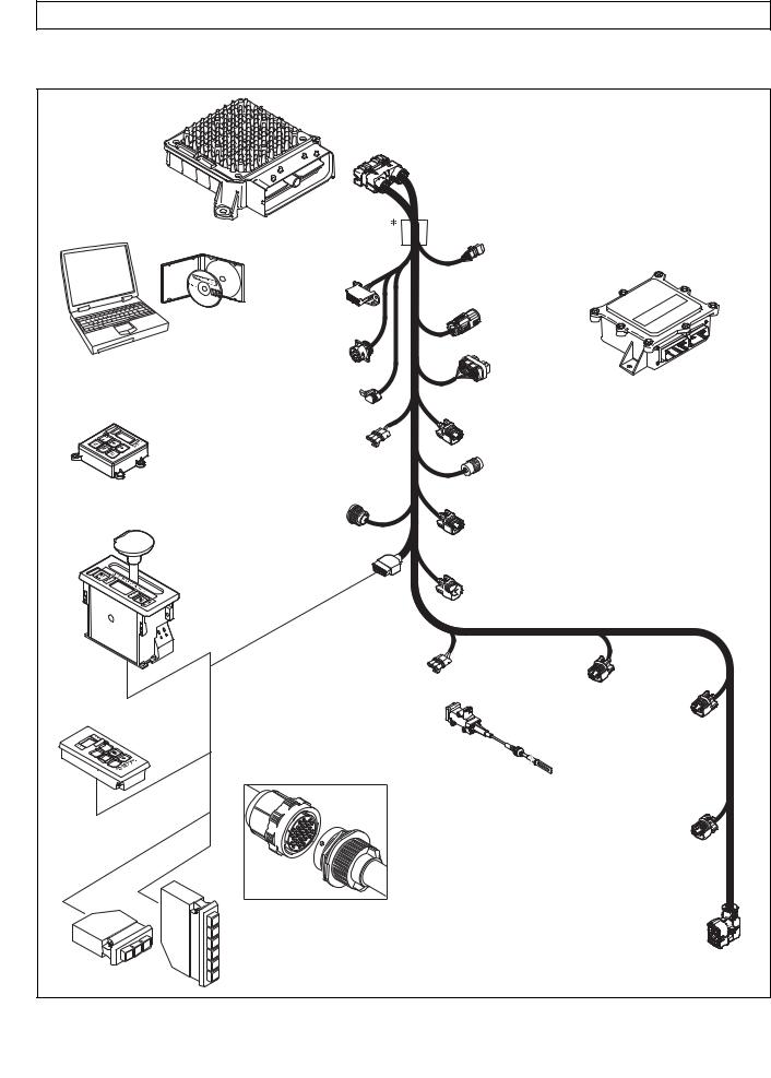
3000 AND 4000 PRODUCT FAMILIES TROUBLESHOOTING MANUAL—ALLISON 4th GENERATION CONTROLS
GENERAL DESCRIPTION
TRANSMISSION CONTROL MODULE (TCM)
ALLISON DOC™
FOR PC — SERVICE TOOL
COMPACT
PUSHBUTTON
SELECTOR
DIAGNOSTIC
TOOL
CONNECTOR
DEUTSCH 9-PIN DIAGNOSTIC TOOL CONNECTOR
SCI (J1587)  CONNECTOR
 (OPTIONAL)
RETARDER
MODULATION
REQUEST (RMR)
CONNECTOR
|
SENSOR HARNESS |
|
|
REMOTE LEVER |
CONNECTOR (OPTIONAL) |
|
SELEC TOR |
|
|
SHIFT |
|
|
SELEC TOR |
|
|
CONNECTOR |
|
VEHICLE |
||
|
INTERFACE |
||
|
J1939 |
MODULE |
|
|
(VIM) |
||
|
CONNECTOR |
||
|
VIW |
||
|
CONNECTOR |
||
|
(OPTIONAL) |
VIM
CONNECTOR
RETARDER ACCUMULATOR
CONNECTOR
TRANSFER CASE CONNEC TOR (3000 PRODUCT FAMILY 7-SPEED)
OUTPUT
SPEED SENSOR
CONNECTOR
RETARDER TEMP.


 SENSOR CONNECTOR
REMOTE PUSHBUTTON SELEC TOR
R
N
D
|
THROTTLE POSITION |
||
|
SENSOR (TPS) |
TURBINE |
|
|
CONNECTOR |
||
|
SPEED SENSOR |
ENGINE |
|
|
CONNECTOR |
SPEED |
|
|
THROTTLE |
(4000 PRODUCT |
SENSOR |
|
FAMILY) |
CONNECTOR |
|
|
POSITION |
||
|
SENSOR (TPS) |
 Bulkhead Connector (Optional)
STRIP PUSHBUTTON SHIFT SELEC TORS (EUROPEAN
OEM)
|
1 |
||
|
2 |
||
|
R |
3 |
|
|
D |
N |
D |
|
N |
||
|
R |
.
NOTE: Illustration is not to scale. Actual harness configuration may differ from this illustration.
RETARDER “PCS5”
SOLENOID
CONNECTOR
20-WAY TRANSMISSION FEEDTHROUGH HARNESS CONNECTOR
V09274.01.00A
Figure 1–2. Typical Allison 4th Generation Control Components
|
1–2 |
Copyright © 2008 Allison Transmission, Inc. |
|
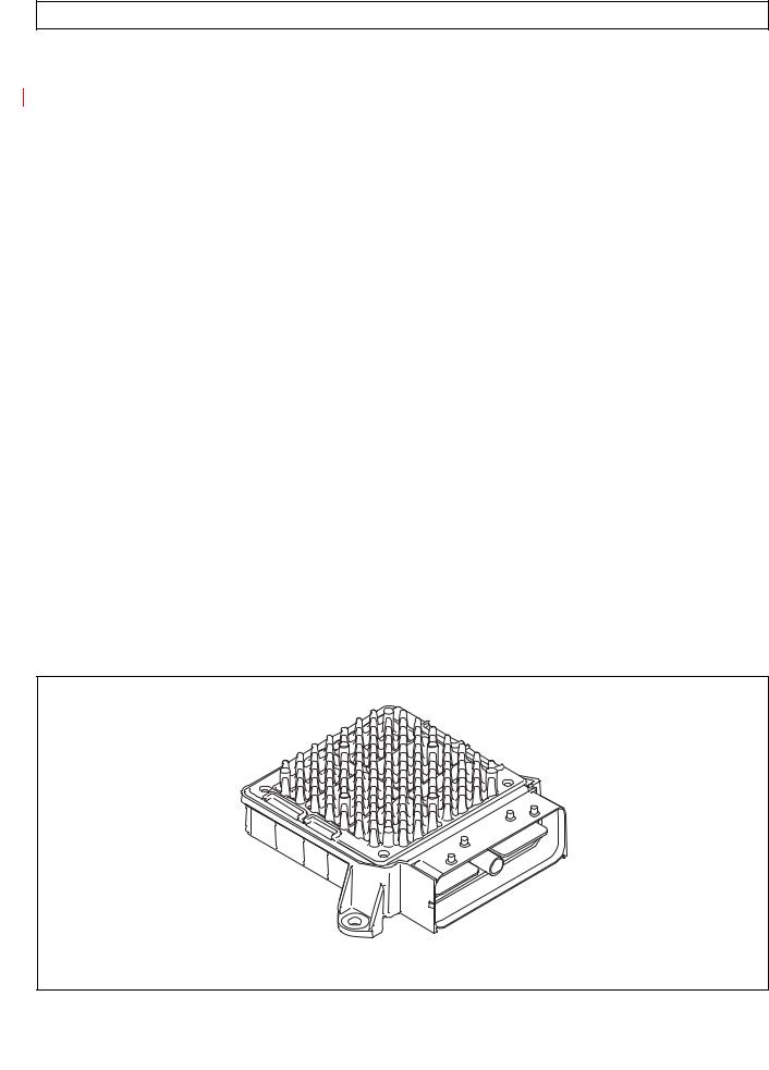
3000 AND 4000 PRODUCT FAMILIES TROUBLESHOOTING MANUAL—ALLISON 4th GENERATION CONTROLS
GENERAL DESCRIPTION
1–2. TRANSMISSION CONTROL MODULE (TCM)
The electronic control of the transmission is performed by a microcomputer. The microcomputer is an independent controller and is referred to as a Transmission Control Module (TCM). TCMs are available in both 12V and 12/24V configurations to match the configuration of the vehicle electrical system.
The TCM (Figure 1–3) contains the microcomputer which is the brain of the control system. The TCM receives and processes information defining:
•Shift selector
•Throttle position
•Sump/retarder temperature
•Pressure switch state
•Engine speed
•Turbine speed
•Transmission output speed.
The TCM uses the information to:
•Control transmission solenoids
•Supply system status
•Provide diagnostic information.
Each TCM has a date code laser etched on the outer case of the TCM. This is the date when the TCM passed final testing. This date is commonly used to denote the change configuration level of the TCM. It is normal for the TCM date displayed electronically to be a few days prior to the date shown on the label.
V09005.00.00
Figure 1–3. Transmission Control Module (TCM)
|
Copyright © 2008 Allison Transmission, Inc. |
1–3 |
|

3000 AND 4000 PRODUCT FAMILIES TROUBLESHOOTING MANUAL—ALLISON 4th GENERATION CONTROLS
GENERAL DESCRIPTION
1–3. SHIFT SELECTOR
Pushbutton and lever shift selectors for the Allison 4th Generation Series are remote mounted from the TCM and communicate to the TCM via the J1939 communications data link. All shift selectors except the strip-type pushbutton have a dual digit vacuum fluorescent (VF) display and a mode indicator (LED). During normal transmission operation, illumination of the LED indicator shows that a secondary or special operating condition has been selected by pressing the MODE button. During diagnostic display mode, illumination of the LED indicator shows that the displayed Diagnostic Trouble Code (DTC) is active. Display brightness is regulated by the same vehicle potentiometer that controls dash light display brightness. More information on both types of shift selectors is continued below.
A.Pushbutton Shift Selector (Figure 1–4)
There are three full-function pushbutton shift selectors and a strip pushbutton shift selector. Strip pushbutton shift selectors are used primarily by non-North American OEMs. A full-function shift selector has a MODE button and diagnostic display capability through the dual digit vacuum fluorescent (VF) display. The strip pushbutton shift selector does not have a MODE button,
diagnostic capability, or adjustable illumination. The full-function pushbutton shift selector has
six (6) pushbuttons which are R (Reverse), N (Neutral), D (Drive), ↓ (Down), ↑ (Up), and MODE. Manual forward range downshifts and upshifts are made by pressing the ↓ (Down) or ↑ (Up) arrow buttons after selecting D (Drive). The N (Neutral) button has a raised lip to aid in finding it by touch.
The MODE button is pressed to select a secondary or special operating condition, such as ECONOMY shift schedule. Diagnostic information is obtained by pressing the ↑ (Up) and ↓ (Down) arrow buttons at the same time.
The strip pushbutton shift selector has either three or six range selection positions as shown in Figure 1–4. When a strip pushbutton shift selector is used, diagnostic information must be obtained by using the Allison DOC™ For PC–Service Tool, or a customer-supplied remote display.
|
1–4 |
Copyright © 2008 Allison Transmission, Inc. |
|
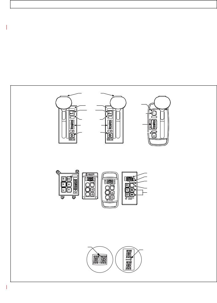
3000 AND 4000 PRODUCT FAMILIES TROUBLESHOOTING MANUAL—ALLISON 4th GENERATION CONTROLS
GENERAL DESCRIPTION
B.Lever Shift Selector (Figure 1–4)
The lever shift selector can have as many as six forward range positions (seven for the 7-speed models), as well as R (Reverse) and N (Neutral). There is a hold override button which must be pressed and held in order to move between certain selector positions. The hold override button must be pressed when shifting between R, N, and D. The hold override button is released when the desired selector position is reached. The selector lever can be moved freely between D and the numbered forward ranges without pressing the hold override button. The lever selector can be chosen with the lever on the left side or on the right side and with the R (Reverse) position toward the front or toward the rear of the selector. Diagnostic and oil level (if sensor is present) information is obtained from the LED display by pressing the “display mode” button.
HOLD OVERRIDE
BUTTON
|
MODE ID |
|||
|
MODE |
|||
|
INDICATOR |
R |
||
|
1 |
(LED) |
||
|
N |
|||
|
2 |
|||
|
MODE BUTTON |
D |
||
|
3 |
|||
|
6 |
|||
|
4 |
|||
|
DIGITAL DISPLAY* |
5 |
||
|
5 |
|||
|
4 |
|||
|
D |
3 |
||
|
N |
|||
|
DISPLAY MODE |
2 |
||
|
R |
|||
|
1 |
|||
|
DIAGNOSTIC |
|||
BUTTON
HOLD OVERRIDE
BUTTON
|
MODE |
|
INDICATOR |
|
(LED) |
|
MODE BUTTON |
MODE ID 

DIGITAL
DISPLAY*
DISPLAY MODE


 DIAGNOSTIC
BUTTON
|
SIX-SPEED, |
SEVEN-SPEED, |
CONTOURED |
|
|
LEFT-HAND |
RIGHT-HAND |
BEZEL |
|
|
LEVER SELECTOR |
LEVER SELECTOR |
||
|
DIGITAL DISPLAY* |
|||
|
MODE ID |
|||
|
MODE |
|||
|
R MODE |
MODE |
INDICATOR (LED) |
|
|
N |
R MODE |
MODE BUTTON |
|
|
N |
Push simultaneously |
||
|
D |
|||
|
D |
to enter diagnostic |
||
|
mode and fluid |
|||
|
level check |
PUSHBUTTON SELECTORS
*NOTE: The first number displayed in the digital display is the highest forward range available and second number is range attained in selected position.
Visually confirm that the range selected was attained. If display is flashing, shift is inhibited.
SERVICE ICON
SERVICE ICON
|
Location of service icon on vertical and horizontal digital display |
V11058.00.00 |
Figure 1–4. Typical Allison 4th Generation Shift Selectors
|
Copyright © 2008 Allison Transmission, Inc. |
1–5 |
|
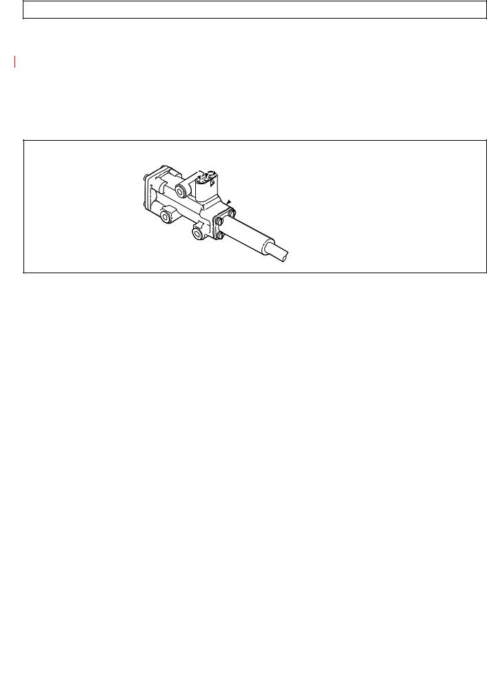
3000 AND 4000 PRODUCT FAMILIES TROUBLESHOOTING MANUAL—ALLISON 4th GENERATION CONTROLS
GENERAL DESCRIPTION
1–4. THROTTLE POSITION SENSOR (Figure 1–5)
The Throttle Position Sensor (TPS) can be mounted to the engine, chassis, or transmission. The TPS contains a pull actuation cable and a potentiometer. One end of the cable is attached to the engine fuel lever and the other, inside a protective housing, to the TPS potentiometer. Output voltage from the TPS is directed to the TCM through the external harness. The voltage signal indicates the throttle position and, in combination with other input data, determines shift timing.
A
 B
B
 C
C
 THROTTLE POSITION SENSOR
V00628
Figure 1–5. Throttle Position Sensor (Without Mounting Brackets)
|
1–6 |
Copyright © 2008 Allison Transmission, Inc. |
|
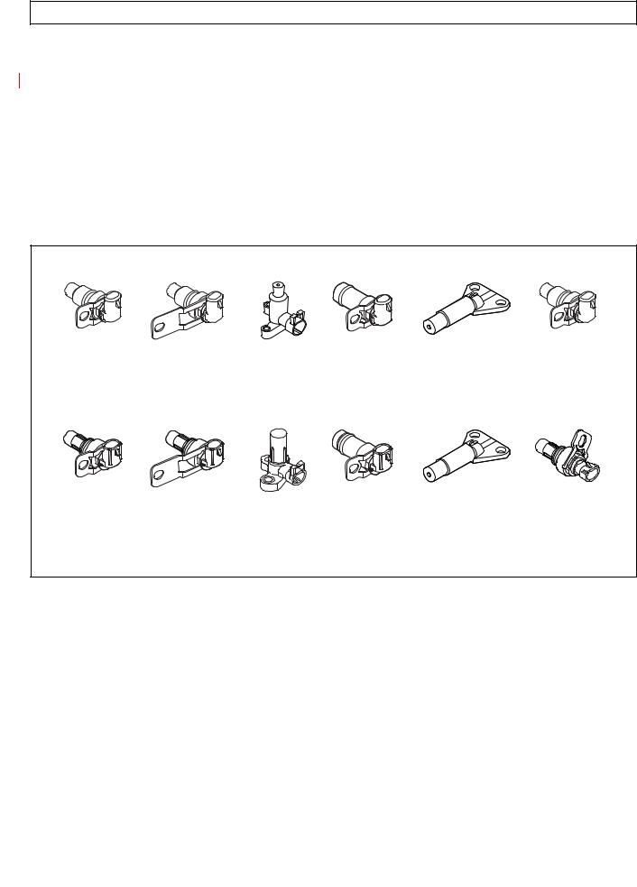
3000 AND 4000 PRODUCT FAMILIES TROUBLESHOOTING MANUAL—ALLISON 4th GENERATION CONTROLS
GENERAL DESCRIPTION
1–5. SPEED SENSORS (Figure 1–6)
Three speed sensors—engine speed, turbine speed, and output speed—provide information to the TCM. The engine speed signal is generated by ribs on the shell of the torque converter pump. The turbine speed signal is generated by the rotating-clutch housing spline contours. The output speed signal is generated by a toothed member attached to the output shaft (except for the 3000 Product Family 7-speed models, where the toothed member is the transfer case idler gear). The speed ratios between the various speed sensors allow the TCM to determine if the transmission is in the selected range. Speed sensor information is also used to control the timing of clutch apply pressures, resulting in the smoothest shifts possible. Hydraulic problems are detected by comparing the speed sensor information for the current range to that range’s speed sensor information stored in the TCM memory.
FORMER (BEFORE JANUARY, 2006)
|
3000 AND 4000 |
4000 |
3000 |
3000 |
3000 |
3000 AND 4000 |
|
PRODUCT FAMILIES |
PRODUCT FAMILY |
PRODUCT FAMILY |
PRODUCT FAMILY |
PRODUCT FAMILY |
PRODUCT FAMILIES |
|
ENGINE |
TURBINE |
TURBINE |
(EXCEPT 7-SPEED) |
7-SPEED OUTPUT |
OUTPUT (EXTERNAL), |
|
(EXTERNAL) |
(EXTERNAL) |
(INTERNAL) |
RETARDER OUTPUT |
(INTERNAL) |
4000 PRODUCT FAMILY |
|
(EXTERNAL) |
RETARDER |
CURRENT (JANUARY, 2006)
|
3000/4000 |
4000 |
3000 |
3000 |
3000 |
3000 AND 4000 |
|
PRODUCT FAMILIES |
PRODUCT FAMILY |
PRODUCT FAMILY |
PRODUCT FAMILY |
PRODUCT FAMILY |
PRODUCT FAMILIES |
|
ENGINE |
TURBINE |
TURBINE |
(EXCEPT 7-SPEED) |
7-SPEED OUTPUT |
OUTPUT (EXTERNAL), |
|
(EXTERNAL) |
(EXTERNAL) |
(INTERNAL) |
RETARDER OUTPUT |
(INTERNAL) |
4000 PRODUCT FAMILY |
|
(EXTERNAL) |
RETARDER |
||||
|
V09819.00.00 |
Figure 1–6. Speed Sensors
|
Copyright © 2008 Allison Transmission, Inc. |
1–7 |
|

3000 AND 4000 PRODUCT FAMILIES TROUBLESHOOTING MANUAL—ALLISON 4th GENERATION CONTROLS
GENERAL DESCRIPTION
1–6. CONTROL MODULE (Figures 1–7 and 1–8)
The Allison 4th Generation Series transmission control module contains a main body assembly and solenoid valve body assembly, which are mounted to an aluminum channel plate. The TCM issues commands to various solenoids in the two valve bodies to govern fluid flow to the clutches (including torque converter clutch). The solenoids produce an output pressure that is proportional to current from the TCM. Hence, the solenoids are referred to as pressure control solenoids (PCS).
|
6-SPEED |
7-SPEED |
|
3000 PRODUCT FAMILY |
3000 PRODUCT FAMILY |
|
CONTROL MODULE |
CONTROL MODULE |
|
6-SPEED |
7-SPEED |
|
4000 PRODUCT FAMILY |
4000 PRODUCT FAMILY |
|
CONTROL MODULE |
CONTROL MODULE |
|
V09276.00.00 |
Figure 1–7. Allison 4th Generation Control Modules
|
1–8 |
Copyright © 2008 Allison Transmission, Inc. |
|
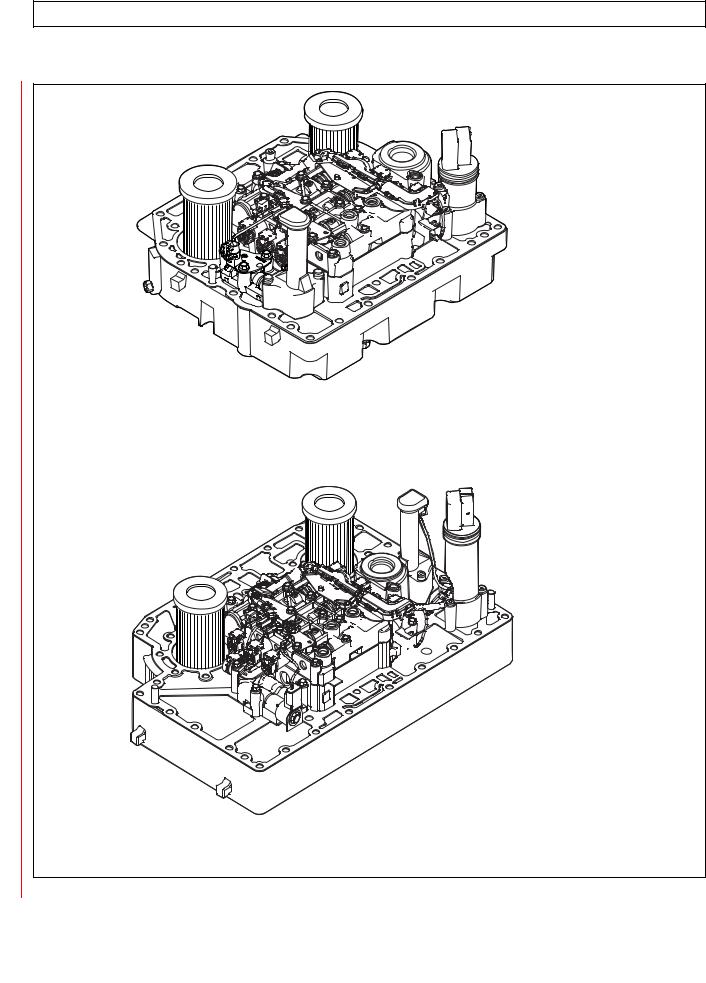
3000 AND 4000 PRODUCT FAMILIES TROUBLESHOOTING MANUAL—ALLISON 4th GENERATION CONTROLS
GENERAL DESCRIPTION
6-SPEED W/PROGNOSTICS
3000 PRODUCT FAMILY
CONTROL MODULE
6-SPEED W/PROGNOSTICS
4000 PRODUCT FAMILY V09276.00.00.A
CONTROL MODULE
Figure 1–8. Allison 4th Generation Control Mudules with Prognostics
|
Copyright © 2008 Allison Transmission, Inc. |
1–9 |
|

3000 AND 4000 PRODUCT FAMILIES TROUBLESHOOTING MANUAL—ALLISON 4th GENERATION CONTROLS
GENERAL DESCRIPTION
The main valve body assembly contains the following:
•Main pressure regulator valve
•Control main regulator valve
•Converter flow valve
•Lube regulator valve
•Converter regulator valve
•Exhaust backfill valve
•Two latching logic valves
•On/Off solenoid SS1.
The solenoid valve body assembly contains the following:
•Pressure control solenoid MAIN MOD
•PCS1 (A trim)
•PCS2 (B trim)
•PCS3 (C trim)
•PCS4 (D trim)
•TCC (lockup)
•Diagnostic pressure switch PS1
•Filter Life Switch (PS2)
•Five solenoid regulator valves
•One diagnostic valve.
The low valve body assembly (in 3000 and 4000 Product Families 7-speed models) contains solenoid PCS6 (C6) and one ON/OFF solenoid SS2 (C6 enable). Refer to the appropriate service manual for valve locations.
The Allison 4th Generation controls system includes a main modulation solenoid. Modulated main pressure results in improved cooler flow and reduced pump losses when throttle position and output speed is low. The Allison 4th Generation Controls TCM commands the main mod solenoid ON when all of the following conditions are simultaneously met:
•Sump temperature is greater than –80ºC (–112ºF) and less than 150ºC (302ºF).
•Engine speed less than 1200 rpm in all ranges except neutral. There are no restrictions on engine speed in neutral.
•Throttle percentage less than 15 percent in reverse, low (7-speed), first, or second range. Main mod may be commanded ON in neutral at any throttle position.
•Output speed is less than 250 rpm in neutral, reverse, low (7-speed), first, or second range.
•The PTO input to the TCM indicates the PTO is OFF.
•Shift not in progress.
The TCM may activate the main mod solenoid for improved clutch control and transmission response during other unusual operating situations.
A temperature sensor (thermistor) is located in the internal wiring harness. Changes in sump fluid temperature are indicated by changes in sensor resistance, which changes the signal sent to the TCM. Refer to the chart in Appendix Q.
The oil level sensor (OLS) is a float type device mounted on the control module channel plate. The OLS senses transmission fluid level by electronically measuring the buoyancy forces on the float. The sensor operates on
|
1–10 |
Copyright © 2008 Allison Transmission, Inc. |
|
![]()
3000 AND 4000 PRODUCT FAMILIES TROUBLESHOOTING MANUAL—ALLISON 4th GENERATION CONTROLS
GENERAL DESCRIPTION
5VDC supplied by the TCM. The oil level sensor is available on any 3000 and 4000 Product Families transmissions except the 3000 7-speed transmissions.
The diagnostic pressure switch PS1 is mounted on the solenoid valve body assembly and performs the following two functions:
•When the C5 clutch is filled, PS1 senses the PCS2 solenoid regulator valve position to verify proper C3 clutch control in reverse, neutral, and first range.
•When the C5 clutch is exhausted, as in second through sixth ranges, PS1 verifies the position of the C1 and C2 latch valves.
The turbine speed sensor is mounted on the control module for the 3000 Product Family transmissions. The turbine speed sensor is directed at the rotating-clutch housing. The turbine speed sensor on the 4000 Product Family transmission is located on the outside of the main housing.
A.Control System Prognostics Operation and Display
The Prognostics Package includes the following functions:
•Oil Life Monitor
•Filter Life Monitor
•Transmission Health Monitor
Use the Allison DOC™ For PC–Service Tool to review the current status of any of these functions and a history of indicator resets. Use the Allison shift selector to review the current status of any of these functions, provided the function being checked is in its specific display mode. See the selector information section for that procedure.
When a specified threshold is detected for any of the prognostic functions, the SERVICE TRANS indicator (an open-ended wrench icon located between the range select and range monitor digits in the Allison shift selector) illuminates to alert the operator. The lamp strategy for the icon varies, either flashing, or steady, to indicate to the operator which function detected the threshold value was reached.
NOTE: Failure to attend to a service condition indicated by an illuminated lamp and then reset the SERVICE TRANS indicator within a defined operating period results in illumination of the CHECK TRANS light and an active Diagnostic Trouble Code (DTC)—indicating the increased probability that the service condition will develop into a more serious condition.
B.Filter Life Valve Body
The Filter Life Valve Body Assembly includes the parts listed here and also shown in Figure 2.
•Filter Life Valve Body
•Filter Life Valve
•Return Spring
•Valve Stop
•Retaining Clip
•Pressure Switch 2 (Filter Life)
•M6 x 45 Long Screws (4)
This assembly cannot be retrofitted to the former channel plate assemblies. Make sure all updates listed in this section and all other requirements are met prior to using the Prognostics features.
|
Copyright © 2008 Allison Transmission, Inc. |
1–11 |
|

3000 AND 4000 PRODUCT FAMILIES TROUBLESHOOTING MANUAL—ALLISON 4th GENERATION CONTROLS
GENERAL DESCRIPTION
1–7. WIRING HARNESSES
A.External Wiring Harness (Figure 1–9)
The TCM uses a single 80-way connector, which is used to receive input from the following:
|
Transmission |
TPS |
Diagnostic tool connector |
|
Engine |
Vehicle interface module (VIM) |
Retarder |
|
Turbine |
Retarder control module |
Retarder temperature sensor |
|
Output speed sensor |
Shift selector |
Accumulator |
|
Filter life switch (PS2) |
Many harnesses will include a bulkhead fitting to separate cab and chassis components. Also, many different styles and materials for harnesses are likely to be encountered.
NOTE: Allison Transmission is providing for service of wiring harnesses and wiring harness components as follows:
•Repair parts for the internal wiring harness and for wiring harness components attached to the shift selector will be available through the Allison Transmission Parts Distribution Center (PDC). Use the P/N from your appropriate parts catalog or from Appendix E in this manual. Allison Transmission is responsible for warranty on these parts.
•Repair parts for the external harnesses and external harness components must be obtained from St. Clair Technologies Inc. (SCTI). SCTI provides parts to any Allison customer or OEM and is responsible for warranty on these parts. SCTI recognizes Allison Transmission, manufacturers, and SCTI part numbers. SCTI provides a technical HELPLINE at 519-627-1673 (Wallaceburg). SCTI will have parts catalogs available. The SCTI addresses and phone numbers for parts outlets are:
|
St. Clair Technologies, Inc. |
St. Clair Technologies, Inc. |
|
920 Old Glass Road |
Calle Damanti S/N Col |
|
Wallaceburg, Ontario, Canada N8A 4L8 |
Guadalupe—Guaymas |
|
Phone: 519-627-1673 |
Sonora, Mexico 85440 |
|
Fax: 519-627-4227 |
Phone: 011-526 2222-43834 |
|
Fax: 011-526-2222-43553 |
• SCTI is the source for external harness repair parts.
|
1–12 |
Copyright © 2008 Allison Transmission, Inc. |
|
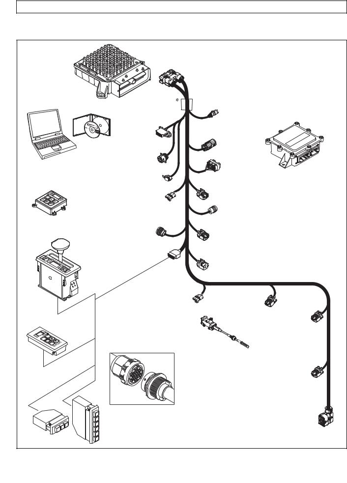
3000 AND 4000 PRODUCT FAMILIES TROUBLESHOOTING MANUAL—ALLISON 4th GENERATION CONTROLS
GENERAL DESCRIPTION
TRANSMISSION CONTROL MODULE (TCM)
ALLISON DOC™
FOR PC — SERVICE TOOL
COMPACT
PUSHBUTTON
SELECTOR
DIAGNOSTIC
TOOL
CONNECTOR
DEUTSCH 9-PIN DIAGNOSTIC TOOL CONNECTOR
SCI (J1587)  CONNECTOR
 (OPTIONAL)
RETARDER
MODULATION
REQUEST (RMR)
CONNECTOR
|
SENSOR HARNESS |
|
|
REMOTE LEVER |
CONNECTOR (OPTIONAL) |
|
SELEC TOR |
|
|
SHIFT |
|
|
SELEC TOR |
|
|
CONNECTOR |
|
VEHICLE |
||
|
INTERFACE |
||
|
J1939 |
MODULE |
|
|
(VIM) |
||
|
CONNECTOR |
||
|
VIW |
||
|
CONNECTOR |
||
|
(OPTIONAL) |
VIM
CONNECTOR
RETARDER ACCUMULATOR
CONNECTOR
TRANSFER CASE CONNEC TOR (3000 PRODUCT FAMILY 7-SPEED)
OUTPUT
SPEED SENSOR
CONNECTOR
RETARDER TEMP.


 SENSOR CONNECTOR
REMOTE PUSHBUTTON SELEC TOR
R
N
D
|
THROTTLE POSITION |
||
|
SENSOR (TPS) |
TURBINE |
|
|
CONNECTOR |
||
|
SPEED SENSOR |
ENGINE |
|
|
CONNECTOR |
SPEED |
|
|
THROTTLE |
(4000 PRODUCT |
SENSOR |
|
FAMILY) |
CONNECTOR |
|
|
POSITION |
||
|
SENSOR (TPS) |
 Bulkhead Connector (Optional)
STRIP PUSHBUTTON SHIFT SELEC TORS (EUROPEAN
OEM)
N
DD N R
NOTE: Illustration is not to scale. Actual harness configuration may differ from this illustration.
RETARDER “PCS5”
SOLENOID
CONNECTOR
20-WAY TRANSMISSION FEEDTHROUGH HARNESS CONNECTOR
V09274.01.00A
Figure 1–9. Typical 4th Generation Electronic Controls External Wiring Harnesses
|
Copyright © 2008 Allison Transmission, Inc. |
1–13 |
|
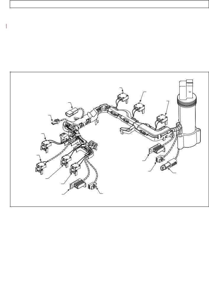
3000 AND 4000 PRODUCT FAMILIES TROUBLESHOOTING MANUAL—ALLISON 4th GENERATION CONTROLS
GENERAL DESCRIPTION
B.Internal Wiring Harness (Figure 1–10)
The internal wiring harness provides connection between the following:
•External harness
•Pressure control and shift solenoids
•Oil level sensor
•Diagnostic pressure switch
•Temperature sensor
•Turbine speed sensor.
|
TCC (LOCKUP) |
||
|
PCS1 (C1) |
||
|
PS1 DIAGNOSTIC |
PCS2 (C2/C3) |
|
|
PRESSURE SWITCH |
||
|
NT1 TURBINE |
||
|
SPEED SENSOR |
||
|
(3000 ONLY) |
||
|
MAIN MOD |
||
|
PCS6 |
||
|
(C6, 7-SPEED) |
SS1 |
|
|
ON/OFF |
||
|
OIL LEVEL SENSOR |
OIL |
|
|
(4000 ONLY) |
||
|
TEMPERATURE |
||
|
PCS4 (C4) |
||
|
SENSOR |
||
|
PCS3 (C3C5) |
||
|
SS2 |
OIL LEVEL SENSOR |
|
|
(3000 AND 4000 PRODUCT |
(3000, EXCEPT 7-SPEED) |
|
|
FAMILIES 7-SPEED C6 ENABLE) |
||
|
V09251.00.00 |
Figure 1–10. Allison 4th Generation Internal Wiring Harness
|
1–14 |
Copyright © 2008 Allison Transmission, Inc. |
|
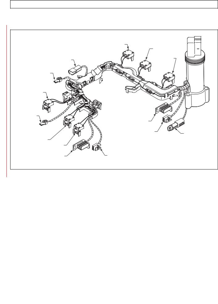
3000 AND 4000 PRODUCT FAMILIES TROUBLESHOOTING MANUAL—ALLISON 4th GENERATION CONTROLS
GENERAL DESCRIPTION
|
TCC (LOCKUP) |
||
|
PCS1 (C1) |
||
|
PS1 DIAGNOSTIC |
PCS2 (C2/C3) |
|
|
PRESSURE SWITCH |
||
|
NT1 TURBINE |
||
|
SPEED SENSOR |
||
|
(3000 ONLY) |
||
|
MAIN MOD |
||
|
PS2 |
||
|
FILTER LIFE |
SS1 |
|
|
ON/OFF |
||
|
OIL LEVEL SENSOR |
OIL |
|
|
(4000 ONLY) |
||
|
TEMPERATURE |
||
|
PCS4 (C4) |
||
|
SENSOR |
||
|
PCS3 (C3C5) |
||
|
SS2 |
OIL LEVEL SENSOR |
|
|
(3000 AND 4000 PRODUCT |
(3000, EXCEPT 7-SPEED) |
|
|
FAMILIES 7-SPEED C6 ENABLE) |
||
|
V09251.00.00.A |
Figure 1–11. Allison 4th Generation Internal Wiring Harness with Prognostics
|
Copyright © 2008 Allison Transmission, Inc. |
1–15 |
|
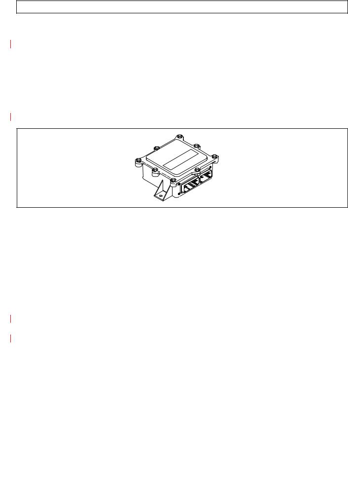
3000 AND 4000 PRODUCT FAMILIES TROUBLESHOOTING MANUAL—ALLISON 4th GENERATION CONTROLS
GENERAL DESCRIPTION
1–8. VEHICLE INTERFACE MODULE (Figure 1–12)
The vehicle interface module (VIM) provides relays, fuses, and connection points for interface with the output side of the vehicle electrical system. VIMs are available for both 12V and 24V electrical systems. The VIM for 12V systems uses all 12V relays. The VIM for 24V systems has all 24V relays. Refer to the appropriate parts catalog for the transmission assembly number that you are servicing for detailed parts information. Refer to Pages D–15 and D–16 for VIM wire number and terminal information.
Some OEMs may provide their own equivalent for the VIM which performs the same functions as the VIM shown in Figure 1–12.
V00631.02
Figure 1–12. Vehicle Interface Module (VIM)
1–9. AUTODETECT FEATURE
Autodetect is active on the first 25 engine starts and, in the case of throttle source detection logic, may continue past 25 ignition cycles until a valid source is determined (details follow in A through D below). Autodetect takes place within the first 30 seconds of each engine start monitored. Autodetect searches for the presence of the following transmission components or data inputs in the priority listed:
|
Retarder |
Present, Not Present |
|
Oil Lever Sensor (OLS) |
Present, Not Present |
|
Throttle |
TPS, J1587, J1939 * |
|
Engine Coolant Temperature |
Sensor, J1939, J1587 |
* No Throttle Autodetect with MY09
Even after autodetect has been completed, it can be reset to monitor an additional group of engine starts. Reset may be necessary if a device known to be present is not detected or if an autodetectable component or sensor was added after the initial vehicle build. Reset is accomplished by using Allison DOC™ For PC–Service Tool. To use the Allison DOC™ For PC–Service Tool, select “RESET AUTODETECT” to search for all four devices. Select “RESET AUTODETECT RETARDER” to search for a retarder only. Selecting “RESET ADAPTIVE SHIFT PARAMETERS” will not reset autodetect logic.
The Allison DOC™ For PC–Service Tool can also be used to override autodetect and manually enter the component or sensor to be recognized by the TCM by changing appropriate “customer modifiable constants” (CMC). The four items above are the only CMCs that are autodetectable. Other CMCs can be changed at any time and are not related to autodetect. Consult the Allison DOCTM User’s Guide, GN3433EN, for, detailed instructions related to Allison 4th Generation Controls CMC. Additional details for each of the four autodetectable features are given below.
|
1–16 |
Copyright © 2008 Allison Transmission, Inc. |
|

3000 AND 4000 PRODUCT FAMILIES TROUBLESHOOTING MANUAL—ALLISON 4th GENERATION CONTROLS
GENERAL DESCRIPTION
A.Retarder
Autodetect searches for the presence of pressure control solenoid 5 (PCS5) to the retarder during the first 35 engine ignition cycles. Retarder autodetect will countdown for a maximum of 35 ignition cycles while recording detections of a retarder. A retarder will be identified as present and the retarder autodetect logic will stop once it is detected for three consecutive ignition cycles. If the ignition cycle counter completes the 35 cycles before there are three consecutive detections of a retarder, the software will log that there is no retarder and the retarder autodetect logic will stop. If the autodetect logic is not satisfied during the first 35 engine starts, the retarder is not detected and will not function on subsequent engine starts.
If a retarder is present but is not detected by autodetect, the retarder will not function. Be sure to determine that the retarder is functioning properly
WARNING: immediately after the 35th engine start. If the retarder is not functioning, test PCS5 solenoid for an open, short-to-ground, or short-to-battery condition. Use
the Allison DOC™ For PC–Service Tool to reset retarder autodetect or to manually select the presence of the retarder after the PCS5 circuit is repaired.
B. Oil Level Sensor (OLS)
NOTE: If an OLS is known to be present but has not been detected, a possible cause is that the transmission fluid level is too low. Determine the fluid level before beginning the OLS troubleshooting.
Oil level sensor autodetect will countdown for a maximum of 25 engine starts while recording detections of an OLS. The TCM monitors the OLS input voltage on wire 116. OLS input voltage must exceed a predetermined level for the TCM to record a detection. Additionally, OLS detection must occur within 12.5 seconds on any given engine start. An OLS will be identified as present and the OLS autodetect logic will stop once it is detected during any single engine start.
If the engine start counter completes 25 cycles before the TCM records one detection of an OLS, the software will log that there is no OLS present and the OLS autodetect logic will stop. Then the TCM concludes that no OLS is present.
No OLS diagnostics take place until the OLS is detected. Frequently test for the presence of oil level diagnostics if the transmission is known to contain an OLS. If an OLS is known to be present, but has not been detected, troubleshooting the OLS circuit is required. After the OLS circuit is repaired, reset autodetect or manually select the OLS function using the Allison DOC™ For PC–Service Tool.
C.Throttle Source
Throttle autodetect will increment a counter for a throttle source on each engine start during which the possible throttle source is detected. When the counter for any of the sources indicates five consecutive detections, the software will set a “confidence flag” to indicate that this is an available throttle source. Multiple throttle sources can be detected on a single engine start and multiple confidence flags can be set. There is no limit to the number of engine starts for autodetection of the throttle source until a confidence flag is set for a source. Once a confidence flag is set for any one of the sources, a counter begins to countdown for 15 additional engine starts. During the entire autodetect period, the software will use the highest priority source as the throttle source if multiple sources are detected before any confidence flags are set. Once a confidence flag is set, that source is used as the source for the throttle signal. When the countdown period is complete, the software will use the highest priority throttle source having a confidence flag set and the autodetect logic will stop.
|
Copyright © 2008 Allison Transmission, Inc. |
1–17 |
|

3000 AND 4000 PRODUCT FAMILIES TROUBLESHOOTING MANUAL—ALLISON 4th GENERATION CONTROLS
GENERAL DESCRIPTION
D.Engine Coolant Temperature
Engine coolant temperature sensor autodetect will countdown for a total of 25 engine starts while recording detections of engine coolant temperature sources. A “confidence flag” will be set once a source is detected for five consecutive engine starts. Multiple sources detected before a confidence flag is set or multiple confidence flags will result in the highest priority source being used as the engine coolant temperature source. Multiple sources can be detected on a single engine start cycle.
1–10. TRANSID (TID)
The TransID feature enables the TCM to recognize various transmission hardware configurations and select an appropriate software calibration. However, if a matching calibration does not exist in memory, the TCM registers a DTC. Furthermore, TID only works when the controller and transmission have the same generation controls. Thus, TID will not allow an Allison 4th Generation TCM to recognize a transmission with WTEC III controls, nor will TID allow a WTEC III ECU to recognize a transmission with Allison 4th Generation Controls.
The TCM senses the transmission configuration using TID wire 176. In initial versions of Allison 4th Generation Controls, wire 176 is connected to high side driver 1 (HSD1), wire 111, in the internal wiring harness. HSD1 supplies power to PCS6 and MAIN MOD solenoids. This wiring configuration is designated TID A.
Whenever a TID level change is to be made, the new TID level calibration will be added to the PROM Calibration Configurator System (PCCS) before the change (s) is (are) made in production to the transmissions. All TCMs programmed and sold after that date will be loaded with the new TID calibration. These TCMs will contain calibrations for the new level transmission and all previous TID levels and will automatically load the correct calibration for the transmission based on the TID signal sensed by Autodetect during the first 25 engine starts.
|
1–18 |
Copyright © 2008 Allison Transmission, Inc. |
|
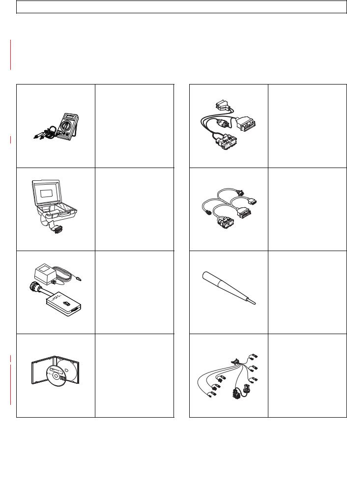
3000 AND 4000 PRODUCT FAMILIES TROUBLESHOOTING MANUAL—ALLISON 4th GENERATION CONTROLS
GENERAL DESCRIPTION
1–11. SPECIAL ELECTRONIC/ELECTRICAL TOOLS
All tools listed are essential for overhaul, maintenance, and/or recalibration of the 3000 and 4000 Product Families electronic and electrical systems. The tools listed below are available for purchase from SPX/Kent-Moore.
Table 1–1. Essential Tools
J 34520-A
Digital
Volt/Ohmmeter
J 39700
Univeral Breakout Box
J 42455-A
Load Box
J 44950
Allison DOC™ For
PC–Service Tool
NOTE: J 44950 is superseded for each new release of Allison DOC™ For PC–Service Tool
J 47275
TCM Breakout
Harness Adapter
NOTE: Used with J 39700.
J 47275
J 47276
“T” Breakout and TCM
Reflashing Harness
J 47276
J 47277
Terminal Probe
NOTE: J 47277 is now included in the J 39197-A Kit.
J 47277
|
* |
J 47279 |
|
* |
3000 and 4000 Product |
|
Families Breakout Harness |
|
|
*NOTE: 4000 Product Family |
|
|
V09224.01.00 |
|
Copyright © 2008 Allison Transmission, Inc. |
1–19 |
|
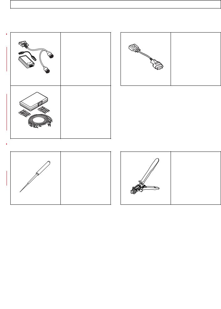
3000 AND 4000 PRODUCT FAMILIES TROUBLESHOOTING MANUAL—ALLISON 4th GENERATION CONTROLS
GENERAL DESCRIPTION
Table 1–1. Essential Tools (cont’d)
|
J 47943-A |
J 47949-A |
|
|
or |
||
|
or |
||
|
J 47943 |
||
|
J 47949 |
||
|
DPA4 (Plus) USB |
||
|
GMLAN Cable |
||
|
Translator Device Kit |
||
|
J 47943 |
J 47949 |
|
|
J 39197 |
||
|
or |
||
|
J 39197-A |
||
|
Jumper Kit |
||
|
NOTE: J 47277 Terminal |
||
|
Probe is now included in |
||
|
the J 39197-A Kit. |
||
|
J 39197-A |
Table 1–2. Available Tools
J 38125-12A
Terminal Remover (80-way connector) GM P/N: 12094429
J 47139 (Former) 63811-6000 (Current) Crimper
|
1–20 |
Copyright © 2008 Allison Transmission, Inc. |
|
![]()
3000 AND 4000 PRODUCT FAMILIES TROUBLESHOOTING MANUAL—ALLISON 4th GENERATION CONTROLS
SECTION 2—DEFINITIONS AND ABBREVIATIONS
2–1. CHECK TRANS LIGHT
When the TCM detects a serious fault, the CHECK TRANS light (usually located on the vehicle instrument panel) illuminates and action is automatically taken to protect operator, vehicle, and the transmission. A Diagnostic Trouble Dode (DTC) will nearly always be registered when the CHECK TRANS light is on; however, not all DTCs will turn on the CHECK TRANS light. Codes related to the CHECK TRANS light are detailed in the diagnostic trouble code chart (refer to Section 6).
Illumination of the CHECK TRANS light indicates that a condition was detected that requires service attention. Operation may or may not be restricted. Even when operation is restricted, the vehicle can be operated to reach a service assistance location. Depending upon the cause for the CHECK TRANS light illumination, the TCM may or may not respond to shift selector requests. The transmission may be locked in a range. That range will be shown on the shift selector display. Both upshifts and downshifts may be restricted when the CHECK TRANS light is illuminated. Seek service assistance as soon as possible.
Each time the engine is started, the CHECK TRANS light illuminates briefly and then goes off. This momentary lighting shows the light circuit is working properly. If the light does not come on during engine start, request service immediately.
A.Oil Life Monitor (OM)
The display message, seen in Allison DOC™ For PC–Service Tool or the Allison shift selector, indicates the calculated remaining life of the transmission fluid. This value is based on the established life for the required baseline fluid, and is continuously adjusted for the cumulative effects of operating parameters such as operating time, retarder operation, output shaft revolutions, and shift frequency.
OM Display: The selector display is a two-digit number, showing the percentage of fluid life remaining. New fluid is displayed as 99 percent. Minimum value displayed is 00 percent. Allison DOC™ For PC–Service Tool displays from 100 percent down to minus (–) 100 percent.
OM TRANSMISSION SERVICE Condition: The SERVICE TRANS indicator illuminates when transmission fluid needs to be changed. This occurs when the remaining fluid life is approximately 1 percent. The indicator is lit upon each initialization of the TCM, and remains on for approximately 1– 2 minutes after the first selection of a drive range, until service is performed and the indicator is reset.
Failure to perform maintenance and reset the SERVICE TRANS indicator within a specified period results in the illumination of the CHECK TRANS light and DTC P0897, Transmission Fluid Deteriorated, being set. P0897 indicates the remaining fluid life has reached 1 percent.
OM Reset: The function may be reset by one of the following methods:
NOTE: Prognostic information can only be reset in the higher of two shift schedules, if applicable.
•Message over the SAE J1939 communication interface.
•With the ignition ON and the engine OFF, shift between N D N D N R N, pausing briefly (less than 3 seconds) between shifts, to reset the value displayed on the shift selector to 99 percent.
•Display the Oil Life Monitor information and press and hold the MODE button of the Allison shift selector for 10 seconds.
•Reset by using the specific Action Request in the Allison DOC™ For PC–Service Tool .
The SERVICE TRANS indicator illuminates briefly following a reset to acknowledge the reset was successful.
|
Copyright © 2008 Allison Transmission, Inc. |
2–1 |

3000 AND 4000 PRODUCT FAMILIES TROUBLESHOOTING MANUAL—ALLISON 4th GENERATION CONTROLS
DEFINITIONS AND ABBREVIATIONS
Allison DOC™ For PC–Service Tool may be used to enable a Customer Modifiable Constant (CMC) within the Prognostics CMC Group to restrict reset to the service tool only. If resets are restricted to the service tool, the selector will not be able to reset the function.
OM History: A historical record of the last 6 resets, including mileage at the time of each reset, may be viewed using the Allison DOC™ For PC–Service Tool .
NOTE: Required calendar-based fluid change intervals are not monitored by this function and those intervals remain applicable to all vehicle installations in addition to the above.
B.Filter Life Monitor (FM)
Filter Life Monitor indicates when the filters require changing. The display message indicates the operating status of the transmission main filter, based on the measured pressure drop across the filter. The Prognostics pressure switch is activated when fluid exiting the main filter drops below a predetermined pressure. Both the main and lube filters must be changed when the SERVICE TRANS indicates the main filter should be changed. The differential pressure limit is verified for a period of time to make sure there is no false filters change indication. This feature is not functional until transmission sump temperatures are between 40º–150ºC (105–302ºF). This feature is not available with 7-speed transmission models.
FM Display: An acceptable filter life status is displayed as OK in the shift selector; an unacceptable filter life status is displayed as LO. Allison DOC™ For PC–Service Tool indicates the Filter Life Monitor expired as YES or NO.
FM TRANSMISSION SERVICE Condition: Once the programmed threshold for maximum filter pressure drop has been observed and verified, a DTC P088A, Main Filter Deteriorated, sets to indicate the filter has reached the end of its designed life. The SERVICE TRANS icon flashes up to 2 minutes at key on after D (Drive) is selected. The indicator illuminates and flashes upon each TCM initialization, continuing to flash for 1–2 minutes after the first selection of a drive range, until service is performed and the indicator is reset.
Failure to perform maintenance and reset the monitor after a calibration-defined number of warnings results in the illumination of the CHECK TRANS light. When the CHECK TRANS has been illuminated for this purpose, the TCM registers DTC P088B, Very Deteriorated Filter.
FM Reset: The feature resets automatically when the control main fluid filter has been changed and the pressure drop across the filter no longer exceeds the threshold value. The lube filter must be changed with the main filter.
The SERVICE TRANS indicator illuminates briefly following a reset to acknowledge the reset was successful.
Manual resets may also be performed by one of the following methods:
•With the ignition ON and the engine OFF, shift between N R N R N D N to reset the value displayed on the shift selector to OK.
•Display the Filter Life Monitor information and press and hold the MODE button of the Allison shift selector for 10 seconds.
•Message over the SAE J1939 communication interface.
NOTE: The Filter Life Monitor triggers the SERVICE TRANS icon following a reset if the Filter Life indicator switch reopens.
|
2–2 |
Copyright © 2008 Allison Transmission, Inc. |

3000 AND 4000 PRODUCT FAMILIES TROUBLESHOOTING MANUAL—ALLISON 4th GENERATION CONTROLS
DEFINITIONS AND ABBREVIATIONS
Allison DOC™ For PC–Service Tool may be used to enable a CMC (Customer Modifiable Constant) within the Prognostics CMC Group to restrict reset to the service tool only. If resets are restricted to the service tool, the selector will not be able to reset the function.
FM History: Use the Allison DOC™ For PC–Service Tool to display the amount of transmission operation from the initial service indication until the service reset.
NOTE: Required calendar-based filter change intervals are not monitored by this feature and remain applicable to all vehicle installations in addition to the above.
C.Operation of Filter Life Valve and Pressure Switch (PS2)
Pressure Switch 2 (PS2), also known as the Filter Life Switch, is used to monitor the pressure difference between main pressure before the filter and lockup clutch pressure as a method to monitor the main filter for excessive filter restriction. See Figure 1.
When the main filter is in an unrestricted state and lockup clutch pressure is applied, the switch is depressurized and in its Normally closed (NC) position which completes a circuit between wire 118 and analog returns wire 158. Allison DOC™ For PC–Service Tool shows PS2 EXHAUSTED. The Filter Life Valve is de-stroked off the return spring in this condition because lockup pressure is high enough to keep main pressure (before the filter) from stroking the valve.
When the main filter gets excessively restricted by debris, lockup pressure drops. The Filter Life Valve strokes because of the higher main pressure (before the filter). This acts on the other end of the Filter Life Valve, compressing the return spring and allowing control main pressure through the valve to PS2, which pressurizes the switch. This opens the PS2 and voltage is sensed on wire 118. Allison DOC™ For PC–Service Tool shows PS2 PRESSURIZED.
|
Copyright © 2008 Allison Transmission, Inc. |
2–3 |

3000 AND 4000 PRODUCT FAMILIES TROUBLESHOOTING MANUAL—ALLISON 4th GENERATION CONTROLS
DEFINITIONS AND ABBREVIATIONS
MAIN CIRCUIT FILTER
FILTER LIFE VALVE
|
MAIN PRESSURE |
EX |
||
|
(BEFORE FILTER) |
|||
|
FILTERED |
CONTROL MAIN |
||
|
MAIN |
PS 2 |
||
|
PUMP |
TCC FLOW |
||
|
FILTERED |
|||
|
SUCTION FILTER |
MAIN |
||
|
EX |
|||
|
SUMP |
LUBE |
||
|
MAIN |
|||
|
FLOW |
|||
|
FILTER LIFE VALVE HYDRAULIC SCHEMATIC |
V11111.00.00 |
Figure 2–1. Filter Life Valve Hydraulic Schematic
D.Transmission Health Monitor (TM)
The display message, seen in Allison DOC™ For PC–Service Tool or the Allison shift selector, identifies clutch life status, as determined by monitored changes and the calculated running clearance of the transmission clutches C1, C2, C3, C4, and C5.
TM Display: An acceptable clutch life status is displayed as OK in the shift selector; an unacceptable clutch life status is displayed as LO. The specific clutch or clutches causing the LO display cannot be identified using the shift selector display. Allison DOC™ For PC–Service Tool displays clutch condition as OK or NOT OK for each clutch, C1 through C5. Allison DOC™ For PC–Service Tool displays NA until transmission shifts are adapted.
TM TRANSMISSION SERVICE Condition: The SERVICE TRANS indicator illuminates, indicating the need for clutch maintenance. This occurs when the remaining clutch life reaches
|
2–4 |
Copyright © 2008 Allison Transmission, Inc. |

3000 AND 4000 PRODUCT FAMILIES TROUBLESHOOTING MANUAL—ALLISON 4th GENERATION CONTROLS
DEFINITIONS AND ABBREVIATIONS
approximately 10 percent or the running clearance exceeds a maximum value, which may indicate a non-wear-related issue. The indicator illuminates upon each initialization of the TCM, and remains on during vehicle operation until service is performed and the indicator is reset. Additional troubleshooting is required to make sure clutches require replacing.
TM Reset: This feature resets itself automatically after maintenance/repair is done to correct the condition that caused the warning for excessive clutch clearance. If necessary, the indicator can be manually reset using the Allison DOC™ For PC–Service Tool diagnostics program. After a number of warnings occur from the SERVICE TRANS indicator without correcting the condition, the CHECK TRANS light illuminates and DTC P2789, Clutch Adaptive Learning at Limit, activates.
TM History: Use the Allison DOC™ For PC–Service Tool to display the amount of transmission operation from the initial service indication until the service reset.
2–2. ALLISON TRANSMISSION DIAGNOSTIC TOOL
Allison DOC™ (Diagnostic Optimized Connection) For PC–Service Tool is a PC-based diagnostic tool for use with 3000 and 4000 Product Families transmissions. The Allison DOC™ For PC–Service Tool is a full-feature diagnostic software application supporting the Allison 4th Generation Control System. When installed on the user’s own PC, it will allow the technician to acquire data from the transmission’s control system and through the use of embedded troubleshooting manuals, conduct systematic troubleshooting of transmission complaints.
Basic Features
Allison DOC™ For PC–Service Tool uses a Windows® style graphical user interface (GUI) and includes:
•User selected views of multiple transmission parameters
•Active and historical diagnostic trouble codes (DTCs)
•Graphical instrument panel view of transmission parameters
•Strip chart function
•User configurable Snapshot function
•User configurable Print function
•Code driven links to embedded Allison 4th Generation Control System Troubleshooting Manuals
•Reprogramming capability (available after satisfying Allison Transmission training certification requirements)
•Demo Mode which allows the user to practice the program without being connected to a vehicle
•New animated screen by screen help support (found in Help, Video-based training materials, Allison DOC™ For PC–Service Tool Training Videos)
•Application Configuration—This menu function serves as the platform for three different features:
(1)General tab, which allows the user to select language (English only at this time), and unit of measure.
(2)TCM Reprogramming tab, used to enable the reprogramming capability of the Allison DOC™ For PC–Service Tool .
(3)Update Application tab, which provides access to a URL containing minor updates for the diagnostic tool to support changes in the various transmission control systems.
•Data Bus Viewer allows the user to capture (see and save) the raw data transmitted on the various vehicle data buses supported by Allison DOC™ For PC–Service Tool (J 1939 and J 2284)
•Printed user’s manual and laminated Job Aid Card
•Adobe® Acrobat Reader® bundled on the CD for reading the Troubleshooting Manual
•Microsoft® Media Player® bundled on the CD for displaying various and updated training videos (available from the application Help menu).
|
Copyright © 2008 Allison Transmission, Inc. |
2–5 |

3000 AND 4000 PRODUCT FAMILIES TROUBLESHOOTING MANUAL—ALLISON 4th GENERATION CONTROLS
DEFINITIONS AND ABBREVIATIONS
PC Platform Definition
Allison DOC™ For PC–Service Tool V7.x.x has been tested with and is known to operate on PCs with the following configurations*:
•Microsoft® Windows® XP® Professional, Windows® 2000 (SP4 or later) Professional, and Windows Vista™ Home Basic (or better)
NOTE: In order to install and run Allison DOC for PC–Service Tool V7.x.x on Windows Vista™, the user must have full administrator privileges and must have the User Acount Control feature turned OFF.
•20 GB Hard Drive (40 GB or greater recommended)
•600 MB free hard drive space required to install the program (after software installation, the operating system requires sufficient free hard disk dpace to run the program)
•1 GHz (or greater) 32-bit (x86) or 64-bit (x64) processor
•512 MB of RAM system memory (1 GB recommended)
•One available USB port—USB 1.1 (USB 2.0 recommended)
•16x CD-ROM (48x or greater recommended)
•Full administrative privileges are required to install, update, and run Allison DOC™ For PC–Service Tool
•Internet connection capability with Internet Explorer® 5.0.1 or greater.
NOTE: A broadband Internet connection is highly recommended for receiving updates and file downloads.
•Windows Media® Player is installed by default
•Adobe® Acrobat Reader® is installed by default
NOTE: Error messages, sudden disconnections, and poor performance are some of the results users will experience if Allison DOC™ For PC-Service Tool V7.x.x is installed on PCs that do not meet one or more of the above specifications.
NOTE: For the latest requirements, please refer to www.allisontransmission.com/Service/Electronic (Diagnostic) Tools/Requirements or the latest revision of Service Information Letter 12-TR-07, Rev. A.
|
2–6 |
Copyright © 2008 Allison Transmission, Inc. |

3000 AND 4000 PRODUCT FAMILIES TROUBLESHOOTING MANUAL—ALLISON 4th GENERATION CONTROLS
DEFINITIONS AND ABBREVIATIONS
2–3. ABBREVIATIONS
|
A/N |
Assembly Number |
|
ABS |
Anti-lock Brake System—OEM-provided means to detect and prevent wheel stoppage to |
|
enhance vehicle handling. Retarder and engine brakes will not apply when ABS is active. |
|
|
Amp |
Unit of electrical current |
|
API |
Application Program Interface |
|
AT |
Allison Transmission |
|
C1…C6 |
Clutch 1….Clutch 6 |
|
CAN |
Controller Area Network—A network for all SAE J1939 communications in a vehicle |
|
(engine, transmission, ABS, etc.) |
|
|
CIN |
Calibration Identification Number |
|
CMC |
Customer Modified Constant |
|
CPA |
Connector Position Assurance |
|
CT |
Closed Throttle |
|
DCE |
Direction Change Enable |
|
DMM |
Digital Multimeter |
|
DNA |
Does Not Adapt—Adaptive shift control is disabled |
|
DNS |
DO NOT SHIFT—Refers to the DO NOT SHIFT diagnostic response during which the |
|
CHECK TRANS light is illuminated and the transmission will not shift and will not |
|
|
respond to the Shift Selector |
|
|
DOC |
Diagnostic Optimized Connection |
|
DPA |
Dearborn Protocol Adapter |
|
DTC |
Diagnostic Trouble Code |
|
DVOM |
Digital Volt/Ohmmeter |
|
ECM |
Engine Control Module |
|
EMI |
ElectroMagnetic Interference |
|
FBO |
Feature Based Ordering |
|
FCC |
Federal Communications Commission |
|
FM |
Filter Life Monitor |
|
GPI |
General Purpose Input—Input signal to the TCM to request a special operating mode or |
|
condition |
|
|
GPO |
General Purpose Output—Output signal from the TCM to control vehicle components |
|
(such as PTOs, backup lights, etc.) or allow a special operating mode or condition |
|
|
GUI |
Graphical User Interface |
|
HSD |
High Side Driver |
|
J1587 |
Engine/transmission serial data communications link |
|
J1939 |
High-speed vehicle serial data communications link |
|
Copyright © 2008 Allison Transmission, Inc. |
2–7 |

3000 AND 4000 PRODUCT FAMILIES TROUBLESHOOTING MANUAL—ALLISON 4th GENERATION CONTROLS
DEFINITIONS AND ABBREVIATIONS
2–3. ABBREVIATIONS (cont’d)
|
LED |
Light-Emitting Diode—Electronic device used for illumination |
|
LRTP |
Low Range Torque Protection |
|
LSD |
Low Side Driver |
|
MB |
Mega Byte |
|
NNC |
Neutral No Clutches—Neutral commanded with no clutches applied |
|
NVL |
Neutral Very Low—The TCM has sensed turbine speed below 150 rpm when output speed |
|
is below 100 rpm and engine speed is above 400 rpm when N (Neutral) was selected. This |
|
|
is usually caused by a dragging C1 or C3 clutch or a failed turbine speed sensor. NVL is |
|
|
attained by turning D solenoid “ON” (in addition to E solenoid) and the C4 and C5 |
|
|
clutches are applied to lock the transmission output. |
|
|
OEM |
Original Equipment Manufacturer—Maker of vehicle or equipment |
|
Ohm |
Unit of electrical resistance |
|
OL |
Over Limit or Oil Level—For Over Limit see “∞”. Indicates Oil Level is being displayed |
|
on a shift selector |
|
|
OLS |
Oil Level Sensor—Electronic device (optional) on control module for indicating |
|
transmission fluid level |
|
|
OM |
Oil Life Monitor |
|
PC |
Personal Computer |
|
PCCS |
PROM Calibration Configurator System |
|
PCS |
Pressure Control Solenoid |
|
PLR |
Primary Lock Reinforcement (Connector) |
|
P/N |
Part Number |
|
PROM |
Programmable Read Only Memory |
|
PSS |
Primary Shift Selector—Main shift selector in a two-selector control system. |
|
PTO |
Power Takeoff |
|
PWM |
Pulse Width Modulation |
|
RELS |
Reduced Engine Load at Stop |
|
RFI |
Radio Frequency Interference |
|
RMR |
Retarder Modulation Request—Signal from a retarder control device |
|
RPR |
Return to Previous Range—Diagnostic response in which the transmission is commanded |
|
to return to previously commanded range |
|
|
RTDR |
Retarder |
|
SCI |
Serial Communication Interface—Used to transmit data and messages between the |
|
diagnostic tool and the TCM and other systems such as electronically-controlled engines. |
|
|
SCTI |
St. Clair Technologies, Inc. |
|
SEM |
Shift Energy Management |
|
2–8 |
Copyright © 2008 Allison Transmission, Inc. |

3000 AND 4000 PRODUCT FAMILIES TROUBLESHOOTING MANUAL—ALLISON 4th GENERATION CONTROLS
DEFINITIONS AND ABBREVIATIONS
2–3. ABBREVIATIONS (cont’d)
|
S/N |
Serial Number |
|
SOH |
State Of Health |
|
SOL OFF |
All SOLenoids OFF |
|
SPI |
Serial Peripheral Interface—The means of communication between the microprocessor |
|
and the interface circuits |
|
|
SS |
Shift Solenoid |
|
SSS |
Secondary Shift Selector—Alternate shift selector in a two-selector control system |
|
TCC |
Torque Converter Clutch |
|
TCM |
Transmission Control Module |
|
TFT |
Transmission Fluid Temperature |
|
TID |
TransID—A feature which allows the TCM to know the transmission configuration and |
|
provide the corresponding calibration required |
|
|
TM |
Transmission Health Monitor |
|
TPA |
Terminal Position Assurance |
|
TPS |
Throttle Position Sensor—Potentiometer for signaling the position of the engine fuel |
|
control lever |
|
|
V |
Version—Abbreviation used in describing TCM software levels |
|
VDC |
Volts Direct Current (DC) |
|
VF |
Vacuum Fluorescent |
|
VIM |
Vehicle Interface Module—A watertight box containing relays and fuses—interfaces the |
|
transmission electronic control system with components on the vehicle |
|
|
VIW |
Vehicle Interface Wiring—Interfaces TCM programmed input and output functions with |
|
the vehicle wiring |
|
|
Volt |
Unit of electrical force |
|
WOT |
Wide Open Throttle |
|
∞ |
Infinity—Condition of a circuit with higher resistance than can be measured, effectively an |
|
open circuit |
|
Copyright © 2008 Allison Transmission, Inc. |
2–9 |

3000 AND 4000 PRODUCT FAMILIES TROUBLESHOOTING MANUAL—ALLISON 4th GENERATION CONTROLS
DEFINITIONS AND ABBREVIATIONS
|
2–10 |
Copyright © 2008 Allison Transmission, Inc. |
![]()
3000 AND 4000 PRODUCT FAMILIES TROUBLESHOOTING MANUAL—ALLISON 4th GENERATION CONTROLS
SECTION 3—BASIC KNOWLEDGE
3–1. BASIC KNOWLEDGE REQUIRED
To service Allison 4th Generation Controls, the technician must understand basic electrical concepts. Most troubleshooting tests consist of determining resistance, continuity, and testing for shorts between wires and to ground. Technicians need to know how to use a digital volt/ohmmeter (DVOM) to make resistance and continuity tests. The technician should be able to use jumper wires and breakout harnesses and connectors. Technicians unsure of making the required tests should ask questions of experienced personnel or find instruction.
The technician should also have the mechanical aptitude required to connect pressure gauges or transducers to identified pressure ports used in the troubleshooting process. Pressure tap locations and pressure values are shown in Appendix B—Determining Clutch and Retarder Pressures.
Input power, ground, neutral start circuitry, etc., can cause problems with electronic controls or vehicle functioning and may not generate a DTC. A working knowledge of the Allison 4th Generation Controls vehicle installation is necessary in troubleshooting installation-related problems.
Refer to Section 8 for information concerning performance complaints (non-code) troubleshooting. A complete wiring schematic is shown in Appendix J. Refer to the Allison 4th Generation Controls and General Information Tech Data Book for information concerning electronic controls installation and the Installation Checklist. Reliable transmission operation and performance depend upon a correctly installed transmission. Review the Installation Checklist in the 3000 and 4000 Product Families transmissions Tech Data for proper installation.
NOTE: Allison Transmission is providing for service of wiring harnesses and wiring harness components as follows:
•Repair parts for the internal wiring harness and for wiring harness components attached to the shift selector will be available through the Allison Transmission Parts Distribution Center (PDC). Use the P/N from your appropriate parts catalog or from Appendix E in this manual. Allison Transmission is responsible for warranty on these parts.
•Repair parts for the external harnesses and external harness components must be obtained from St. Clair Technologies Inc. (SCTI). SCTI provides parts to any Allison customer or OEM and is responsible for warranty on these parts. SCTI recognizes Allison Transmission, manufacturers, and SCTI part numbers. SCTI provides a technical HELPLINE at 519-627-1673 (Wallaceburg). SCTI will have parts catalogs available. The SCTI addresses and phone numbers for parts outlets are:
|
St. Clair Technologies, Inc. |
St. Clair Technologies, Inc. |
|
920 Old Glass Road |
Calle Damanti S/N Col |
|
Wallaceburg, Ontario, Canada N8A 4L8 |
Guadalupe—Guaymas |
|
Phone: 519-627-1673 |
Sonora, Mexico 85440 |
|
Fax: 519-627-4227 |
Phone: 011-526 2222-43834 |
|
Fax: 011-526-2222-43553 |
3–2. USING THE TROUBLESHOOTING MANUAL
Use this manual as an aid to troubleshooting the Allison 4th Generation Controls. Every possible problem and its solution cannot be encompassed by any manual. However, this manual does provide a starting point from which most problems can be resolved.
Once a problem solution is discovered in the manual do not look further for other solutions. It is necessary to determine why a problem occurred. The root cause of a problem as well as the symptom must be corrected to be sure of trouble-free operation. For example, taping a wire that has been rubbing on a frame rail will not correct the problem unless the rubbing contact is eliminated.
|
Copyright © 2008 Allison Transmission, Inc. |
3–1 |

3000 AND 4000 PRODUCT FAMILIES TROUBLESHOOTING MANUAL—ALLISON 4th GENERATION CONTROLS
BASIC KNOWLEDGE
3–3. SYSTEM OVERVIEW
Allison 4th Generation Control functions are controlled by the TCM. The TCM reads the following to determine when to command a shift:
•Shift selector range selection
•Output speed
•Throttle position.
In order to control the oncoming and off-going clutches during a shift, the TCM monitors:
•Turbine speed
•Output speed
•Throttle position.
When the TCM detects an electrical fault, it logs a DTC indicating the faulty circuit and may alter the transmission operation to prevent or reduce damage.
When the TCM detects a non-electrical problem while trying to make a shift, the TCM may try that shift a second or third time before setting a DTC. Once that shift has been retried, and a fault is still detected, the TCM sets a DTC and holds the transmission in a fail-to-range mode of operation.
3–4. IMPORTANT INFORMATION IN THE TROUBLESHOOTING PROCESS
A.Before Beginning Troubleshooting
Before beginning the troubleshooting process, read and understand the following:
•Allison Transmission recommended wire numbers (i.e. 158) all use a “1” for the first digit and the pin-out information at the TCM for the second and third digits.
•Shut off the engine and ignition before any harness connectors are disconnected or connected.
•Remember to do the following when testing for shorts and opens:
—Minimize movement of wiring harnesses when looking for shorts. Shorts involve wire-to-wire or wire-to-ground contacts and moving the harnesses may eliminate the problem.
—Wiggle connectors, harnesses, and splices when looking for opens. This simulates vehicle movements which occur during actual operation.
•When disconnecting a harness connector, be sure the pulling force is applied to the connector itself and not the wires extending from the connector.
•Resistance tests involving wiring between the TCM connector and other components adds about one Ohm of resistance to the component resistance shown.
•Inspect all connector terminals for damage. Terminals may have been bent or lost the necessary tension to maintain firm contact.
•Clean dirty terminals or connectors with isopropyl alcohol and a cotton swab, or a good quality, non-residue, non-lubricating, cleaning solvent such as LPS Electro Contact Cleaner® or LPS NoFlash Electro Contact Cleaner®.
|
3–2 |
Copyright © 2008 Allison Transmission, Inc. |

3000 AND 4000 PRODUCT FAMILIES TROUBLESHOOTING MANUAL—ALLISON 4th GENERATION CONTROLS
BASIC KNOWLEDGE
The cleaning solvent must not be:
• Chlorine based
• Contain petroleum distillates
• Conduct electricity.
|
CAUTION: |
The cleaning solvent should evaporate quickly to prevent the possibility of |
|
condensation within the connectors. Always blow or shake any excess cleaner from |
|
|
the connector before assembling it to its mating connector or hardware. Cleaner |
|
|
trapped in the connector can affect the connector seal. Refer to SIL 17-TR-94, latest |
|
|
revision, for detailed information on the recommended cleaners. |
|
CAUTION: |
Care should be taken when welding on a vehicle equipped with electronic controls. |
|
|
Refer to Appendix G, Paragraph 1–1. |
||
•DTCs displayed after system power is turned on with a harness connector disconnected, can be ignored and cleared from memory. Refer to Section 6, Diagnostic Trouble Codes, for the code clearing procedure.
NOTE: Turn off the vehicle HIGH IDLE switch, if present, before shifting from N (Neutral) to D (Drive). D (Drive) or R (Reverse) will not be attained unless the shift is made with the engine at idle. Also, be aware of other interlocks that would prevent attaining D (Drive) or R (Reverse). Examples are “wheelchair lift not stored” and “service brakes not applied” (service brake interlock present).
B.Cold Weather Starts
All Highway Series transmissions are programmed to restrict full operation until specific fluid temperatures are reached. Refer to the Table 3–1 for temperature restrictions.
Table 3–1. Minimum Fluid Operating Temperatures
|
Sump Fluid Temperature |
CHECK TRANS |
Operation |
|
|
Light |
|||
|
–32ºC to –7ºC (–25ºF to 19ºF) |
OFF |
Neutral, Reverse, Second |
|
|
–7ºC (19ºF) |
OFF |
Full operation in all ranges |
|
NOTE: When sump temperature is below 10ºC (50ºF) and transmission fluid is C4 (not DEXRON® or TranSynd™), follow these procedures when making directional shift changes:
•To shift from forward to reverse, select N (Neutral) and then R (Reverse).
•To shift from reverse to forward, select N (Neutral) and then D (Drive) or other forward range.
Failure to follow these procedures may cause illumination of the CHECK TRANS light and the transmission will be restricted to N (Neutral).
Transmission operation at cold ambient temperatures may require preheating or the use of a lower viscosity transmission fluid.
|
Copyright © 2008 Allison Transmission, Inc. |
3–3 |

3000 AND 4000 PRODUCT FAMILIES TROUBLESHOOTING MANUAL—ALLISON 4th GENERATION CONTROLS
BASIC KNOWLEDGE
C.High Fluid Temperature
The transmission is considered to be overheated when any of the temperatures in Table 3–2 are exceeded:.
Table 3–2. Maximum Allowable Transmission Fluid Temperature
|
Location of Fluid |
Temperature |
|
Sump fluid |
121ºC (250ºF) |
|
Fluid to cooler |
149ºC (300ºF) |
|
Retarder out fluid |
165ºC (330ºF) |
If the transmission overheats during normal operation, use the Oil Level Sensor (OLS), if equipped, to check for correct fluid level. Refer to Section 5-2 for this procedure.
The engine should never be operated for more than ten (10) seconds at full throttle
CAUTION: with the transmission in range and the output stalled. Prolonged operation of this type will cause the transmission fluid temperature to become excessively high and
will cause severe overheat damage to the transmission.
If the engine temperature gauge indicates a high temperature, the transmission is probably overheated. Stop the vehicle and inspect the cooling system. If it appears to functioning p[roperly, run the engine at 1200–1500 rpm with the transmission in N (Neutral). This should reduce the transmission and engine temperature to normal operating levels in two to three minutes. If temperatures do not decrease, reduce the engine rpm.
If the engine temperature indicates a high temperature, an engine or radiator problem is indicated. If high temperature in either the engine or transmission persists, stop the engine and have the overheating condition investigated by maintenance personnel.
3–5. BEGINNING THE TROUBLESHOOTING PROCESS
NOTE:
•Whenever a transmission is overhauled, exchanged, or has undergone internal repairs, the TCM MUST
BE RESET TO FACTORY VALUES by selecting “Reset To Unadapted Shifts” (all), and “Reset Autodetect Information” in Allison DOC™ For PC–Service Tool.
•Be sure the transmission model matches the calibration in the TCM.
1.Begin troubleshooting by determining the transmission fluid level and TCM input voltage. Remember that some problems may be temperature related. Do troubleshooting at the temperature level where the problem occurs. Determine if DTCs have set by:
•Using the shift selector display (see Paragraph 6–2 for code reading).
•Using the Allison DOC™ For PC–Service Tool.
2.When a problem exists but a DTC is not indicated, refer to the Performance Complaint Section (Section for a listing of various electrical and hydraulic problems, their causes, and remedies.
3.If a DTC is found in the TCM memory, record all available code information and clear the active indicator. Refer to Section 6.
|
3–4 |
Copyright © 2008 Allison Transmission, Inc. |

3000 AND 4000 PRODUCT FAMILIES TROUBLESHOOTING MANUAL—ALLISON 4th GENERATION CONTROLS
BASIC KNOWLEDGE
4.Test drive the vehicle to confirm a DTC or performance complaint.
•If the code reappears, refer to Section 6, Diagnostic Trouble Code, and the appropriate code chart. The Diagnostic Trouble Code section lists DTCs and their description. Locate the appropriate troubleshooting chart and follow the instructions.
•If the code does not reappear, it may be an intermittent problem. Use the Allison DOC™ For PC– Service Tool and the code display procedure described in Section 6. The code display procedure will indicate the number of times the DTC has occurred. Refer to the troubleshooting chart for the possible cause(s) of the problem.
•Appendix A deals with the identification of potential circuit problems. Refer to Appendix A if a circuit problem is suspected.
5.If difficulties arise, you have unanswered questions, or if you are unable to quickly identify the root cause during troubleshooting, please contact the Technical Assistance Center (TAC):
Technical Assistance Center PO Box 894, Mail Code A01 Indianapolis, IN 46206-0894 Phone: 1-800-252-5283
NOTE: Information concerning specific items is contained in the appendices located in the back of this manual. The appendices are referred to throughout the manual.
3–6. TCM DIAGNOSTIC PROCEDURE
•Use the Allison DOC™For PC–Service Tool to verify the current calibration information number (CIN) and record or print a report of the current customer modifiable constants (CMC) information for later reference.
•Remove the 80-way connector from the suspect TCM; inspect the connector for damaged or bent pins.
•Replace the TCM with a known, good TCM from a similar vehicle.
NOTE: If using a TCM from another vehicle is unavoidable, the TCM MUST BE set to factory values and the vehicle MUST BE driven carefully to adapt the shifts to the test vehicle. Refer to SIL 16-WT-96 for the correct procedure. Be sure to reset the Adaptive Shift parameters and Autodetect information when it is installed in the original vehicle.
•If the replacement TCM corrects the original complaint, reinstall the original TCM to verify that the complaint returns. If the complaint is confirmed. install a new TCM.
•If the complaint does not return, leave the original TCM installed. Disconnecting and reconnecting the TCM can often correct faulty wiring harness connections that may have been present.
•Clear any DTCs that may be present and test drive the vehicle to confirm the repair.
NOTE: All Allison 4th Generation Controls TCMs are designed to be isolated from the vehicle chassis ground. Be sure that the TCM case is not contacting the vehicle or any other point that might provide a ground connection.
|
Copyright © 2008 Allison Transmission, Inc. |
3–5 |

3000 AND 4000 PRODUCT FAMILIES TROUBLESHOOTING MANUAL—ALLISON 4th GENERATION CONTROLS
BASIC KNOWLEDGE
3–7. RESETTING A TCM PARAMETERS TO SUPPORT ENGINE UPDATE
Shift Energy Management (SEM) Autoselect feature may be used on certain transmissions. Autoselect is deactivated following the first 20 engine starts where engine and transmission communication are present. If during the first 20 starts the TCM recognizes an engine to be on its list of certified engines, it will lock to the SEM active state. If the engine is not supported, the TCM will lock to a non-SEM state.
NOTE: Most engine upgrades are same type/rating; under normal circumstances there should be no reason to reset the TCM Autoselect.
However, there may be a small chance that transmission performance, shift quality, or codes may result from the use of different models within the same engine family or when a recalibration of engine software has taken place. If a vehicle receives upgraded engine hardware or software it may become necessary to reactivate the Autoselect feature to redetect the engine current SEM status.
NOTE: Once TCM Autoselect locks, the only way to reactivate is to perform a reset procedure (refer to Paragraph 3–8).
3–8. RESETTING TCM AUTOSELECT
Verify a new engine rating by checking the engine data tag. The engine must be compatible with the transmission rating. If engine rating is not compatible, the vehicle must be returned to the OEM for engine recalibration. If the rating is correct for the transmission, perform the following steps.
Allison DOC™ for PC–Service Tool is used to reset Autoselect function as follows:
•Display the Action Request menu.
•On the drop down menu, select Reset SEM Autodetect.
•Click on the OK button.
The TCM is now reset to Autoselect and will start looking for supporting engine software. Drive the vehicle; confirm DTCs have not returned.
NOTE: Transmission shifts will now be in the unadaptive (base) state, so it will be necessary to drive the vehicle to allow shift to converge.
3–9. HYDRAULIC OPERATION DURING ELECTRICAL INTERRUPTION
NOTE: The terms left, right, up, and down are directions on the figures and hydraulic schematics referenced by the descriptions in this section.
The solenoid regulator valves are controlled by solenoids that control transmission clutch application. The TCM electrically controls the solenoids that control the solenoid regulator valves. Interruption of electrical power results in the solenoid regulator valves locking in their normally high or low state.
The system that enables the transmission to default to totally hydraulic operation has been incorporated to minimize the impact of an electrical interruption. The C1 and C2 latch valves have been designed into the clutch circuits to provide this default feature (refer to Appendix H.).
When a clutch is applied, clutch feed pressure is routed through the latch valves to the clutch piston. Clutch-apply pressure against the lands of the latch valves hold the latch valves in place or in a normally closed valve allows the fluid to simply flow through the valves. During an electrical interruption, the latch valves cause the transmission to engage specific clutches based on the range in which the transmission was operating when the interruption occurred.
|
3–6 |
Copyright © 2008 Allison Transmission, Inc. |

3000 AND 4000 PRODUCT FAMILIES TROUBLESHOOTING MANUAL—ALLISON 4th GENERATION CONTROLS
BASIC KNOWLEDGE
The latch valves (refer to Appendix H) are activated by normally low solenoid SS1. When SS1 is energized, control main pressure flows to the top of C1 and C2 latch valves. This pressure forces the valves down to connect the necessary flow passages for clutch engagement. The exception is when C5 clutch is applied. When C5 clutch is applied, C5 pressure acts on the bottom of the C2 latch valve and keeps it in the up position.
During an electrical interruption, the latch valves and two normally high, PCS1 and PCS2, enable the transmission to operate in a “limp mode”, allowing the operator to drive the vehicle to a location where it can be serviced.
On 7-speed models, SS2 latch valve takes the place of C5 on the bottom of the C2 latch valve. When SS2 is on, the valve is kept up by SS2.
The default system enables the transmission to revert to total hydraulic operation and provides safe operation during an electrical interruption by shifting to a specific pre-determined range.
Table 3–3 lists the operating range and pre-determined default range the transmission will shift to in the event of an electrical interruption.
Table 3–3.
|
Initial Operating Range |
Hydraulic Default Range* |
|
|
(Power Off; All Solenoids OFF) |
||
|
Reverse |
Neutral |
|
|
(C3 Clutch Applied) |
||
|
Neutral |
Neutral |
|
|
(C3 Clutch Applied) |
||
|
Low (7-speed only) |
3 |
|
|
1 |
3 |
|
|
2 |
3 (during shift to 2nd) |
|
|
4 (following shift) |
||
|
3 |
4 |
|
|
4 |
4 |
|
|
5 |
4 |
|
|
6 |
4 (during shift to 6th) |
|
|
5 (following shift) |
||
|
* Some transmissions used in oil field service default to neutral |
||
|
when power is OFF. |
||
|
Copyright © 2008 Allison Transmission, Inc. |
3–7 |

3000 AND 4000 PRODUCT FAMILIES TROUBLESHOOTING MANUAL—ALLISON 4th GENERATION CONTROLS
BASIC KNOWLEDGE
NOTES
|
3–8 |
Copyright © 2008 Allison Transmission, Inc. |

3000 AND 4000 PRODUCT FAMILIES TROUBLESHOOTING MANUAL—ALLISON 4th GENERATION CONTROLS
SECTION 4—WIRE TEST PROCEDURES
4–1. TESTING FOR OPENS, SHORTS BETWEEN WIRES, AND SHORTS-TO-GROUND
(Use Digital Volt/Ohmmeter J 34520-A and Jumper Wire Set J 39197 or J 39197-A)
NOTE: Please refer to Paragraph 3–5 to begin the troubleshooting process.
1.Make sure all connectors are tightly connected and re-test the circuit.
2.Disconnect and inspect all connectors.
Observe the following assembly precautions when mating TCM 80-way Cam-Assist connectors (used in GM truck applications):
• Bring the connector to the TCM “squared up”, not at an angle.
• Keep hands away from the handle, squarely press the connector onto the
|
CAUTION: |
TCM until the cam lever handle moves of its own accord approximately |
|
|
3⁄4 inch. |
||
|
• Gently complete mating the connector to the TCM by moving the cam lever |
||
|
handle to the locked position. |
||
|
• Slide the CPA into the secondary lock. |
||
|
Failure to do so could cause damage to the internal latching mechanism. |
3.Thoroughly clean corroded or dirty terminals. If dirty or corroded terminals are the probable cause of the problems, reconnect the clean connectors and operate the vehicle normally. If the problem recurs, proceed with Step (4).
The cleaning solvent must not be:
• Chlorine based
• Contain petroleum distillates
• Conduct electricity.
|
CAUTION: |
The cleaning solvent should evaporate quickly to prevent the possibility of |
|
condensation within the connectors. Always blow or shake any excess cleaner from |
|
|
the connector before assembling it to its mating connector or hardware. Cleaner |
|
|
trapped in the connector can affect the connector seal. Refer to SIL 17-TR-94, latest |
|
|
revision, for detailed information on the recommended cleaners. |
4.Review the Allison 4th Generation Controls wire numbering system described in Paragraph 3–4.
5.If all connectors are clean and connected correctly, determine which wires in the chassis harness are indicated by the DTC. For example, Code P0960, indicates an open in the pressure control solenoid circuit, wires 111 and 174.
a. Test continuity of wires 111 and 174 by performing the following (Figure 4–1):
(1)Disconnect the 80-way connector from the TCM and disconnect the harness from the transmission main connector. At one end of the harness, using jumper wire kit J 39197 or J 39197-A, connect wires 111 and 174 to each other, being careful not to distort the terminals. Jumpering the wires together creates a circuit between wires 111 and 174.
Do not insert test probes larger than 0.81 mm into the TCM 80-way and transmission 20-way connectors. Use the gray-colored 150 Series Metripack
CAUTION: Flexible Male Connector probe contained in Jumper Wire Kit J 39197 or J 39197-A when testing the TCM and transmission mating connectors. Failure to do so may
distort the socket terminals inside the connectors and cause them to lose the necessary tension to maintain firm contact.
|
Copyright © 2008 Allison Transmission, Inc. |
4–1 |

3000 AND 4000 PRODUCT FAMILIES TROUBLESHOOTING MANUAL—ALLISON 4th GENERATION CONTROLS
WIRE TEST PROCEDURES
(2)On the opposite end of the harness, test the continuity of the jumpered pair. No continuity in a jumpered pair circuit (infinite resistance reading) indicates an open in the wire being tested. Locate and repair the damaged portion of the wire.
b.If the continuity test is good (0–2 Ohms resistance), remove the jumpers. Test the harness for shorts between wires and shorts-to-ground by performing the following (Figure 4–2):
(1)At the TCM end of the harness, touch one probe of a digital volt/ohmmeter (DVOM) to one wire of the circuit being tested and touch the other probe to each terminal in the same connector, then touch the probe to chassis ground and to the transmission main housing. Do this for both wires in the circuit being tested.
(2)If at any time the DVOM shows zero to low resistance, or the meter’s continuity beeper sounds, there is a short between the two points being probed—wire-to-wire or wire-to-ground. Isolate and repair the short.
BULKHEAD CONNECTOR WIRING HARNESS
FEEDTHROUGH
HARNESS
CONNECTOR
DIGITAL VOLT/OHM-METER (DVOM)
Circuit has continuity. Jumper between wires produces
a complete circuit.
DVOM reading is near zero Ohms.
 JUMPER
0
– +
Figure 4–1. Open Circuit
TRANSMISSION CONNECTOR
WIRING HARNESS
|
Wires shorted |
||
|
together |
||
|
0 |
TCM |
0 |
|
80-WAY |
||
|
– |
CONNECTOR |
– |
|
+ |
+ |
|
|
DIGITAL VOLT/OHM-METER |
||
|
(DVOM) |
 OHMS
OHMS
Circuit does not have continuity due to a broken wire (open circuit).
DVOM reading is very high
(infinite Ohms or OL – overlimit).
V03374.02.00
 Shorted to ground on metal frame rail
Ground to metal frame rail
|
0 OHMS |
0 OHMS |
|
Two wires have frayed and are shorted together. |
Harness has been chafed and one or more wires are |
|
Continuity beeper of DVOM will sound, |
shorted-to-ground. DVOM continuity beeper will sound, |
|
or reading will go to zero Ohms when these |
or reading will go to zero Ohms when meter is probing |
|
two wires are probed with the DVOM. |
between this wire and chassis ground. |
V03375.01.00
Figure 4–2. Short Between Wires and to Ground
|
4–2 |
Copyright © 2008 Allison Transmission, Inc. |
|
Error code |
Description |
Lamp Check trans |
Control system response |
|
C1312 |
Retarder trigger low voltage |
off |
Retarder does not turn on |
|
C1313 |
Retarder trigger signal high voltage |
off |
Retarder does not turn on |
|
P0122 |
Intermittent or low gas pedal position sensor signal |
off |
Default value is used |
|
P0123 |
High gas pedal position sensor |
off |
Default value is used |
|
P0218 |
Oil temperature is too high |
off |
A control pattern is used in case of temperature |
|
P0562 |
Control unit low voltage |
off |
Prohibition of torque converter lockout. DNA |
|
P0602 |
The control unit is not programmed |
On |
Remains neutral |
|
P0610 |
Error of additional equipment of the car with the control unit |
On |
Uses TID A Calibration Data |
|
P0613 |
Control Unit CPU Error |
off |
All solenoids are off |
|
P0614 |
Incompatibility of ECM and TCM data for engine torque control |
On |
Only neutral, reverse and second gear. Torque lock inhibit, shift adaptation disabled |
|
P0634 |
Control unit temperature exceeded |
On |
DNS , SOL OFF , actively hydraulic control. |
|
P063E |
There is no input signal about the position of the throttle during auto detection |
On |
Default value is used |
|
P063F |
No coolant temperature signal during auto detection |
off |
— |
|
P0657 |
Open circuit HSD1 |
On |
SOL OFF , DNA . Prohibition of torque converter lock, prohibition of main |
|
P0658 |
Low voltage in the HSD circuit 1 |
On |
DNS , SOL OFF , hydraulic control is active |
|
P0659 |
High voltage in the HSD circuit 1 |
On |
DNS , SOL OFF , hydraulic control is active |
|
P0702 |
The control unit did not recognize the automatic transmission configuration |
On |
Uses standard configuration |
|
P0703 |
Malfunction in a chain of the gauge of a brake |
off |
On garbage trucks, the inclusion of N — D is not possible . If the code is active, then |
|
P0708 |
High signal from the current gear sensor. |
On |
Ignores the signal of the strip switch |
|
P070C |
Low oil level sensor signal |
off |
— |
|
P070D |
High oil level sensor signal |
off |
— |
|
P0711 |
Abnormal oil temperature sensor signal |
On |
Uses the default temperature |
|
P0712 |
Low oil temperature sensor signal |
On |
Uses standard temperature |
|
P0713 |
High oil temperature sensor signal |
On |
It uses the standard value tamper Aturi |
|
P0716 |
Turbine wheel speed sensor abnormal signal |
On |
DNS , automatic transmission is blocked on the current transfer |
|
P0717 |
No turbine wheel speed sensor signal |
On |
DNS , automatic transmission is blocked on the current transfer |
|
P0719 |
ABS brake signal low |
off |
Takes ABS off |
|
P071A |
Incompatible RELS Input |
On |
RELS function is disabled |
|
P071D |
Incorrect special function input (wire 101 and 142) |
On |
— |
|
P0721 |
Abnormal output speed sensor signal |
On |
DNS , automatic transmission remains in the current transmission |
|
P0722 |
No output speed sensor signal |
On |
DNS , automatic transmission remains in the current transmission |
|
P0726 |
Abnormal engine speed sensor signal |
off |
Uses standard turbine speed |
|
P0727 |
Missing engine speed sensor signal |
off |
Uses standard turbine speed |
|
P0729 |
6th gear ratio incorrect |
On |
DNS , trying to enable 5th , then 3rd gear |
|
P0731 |
1st gear ratio incorrect |
On |
DNS , trying to enable 2nd, then 5th gear |
|
P0732 |
2nd gear ratio incorrect |
On |
DNS , trying to enable 3rd, then 5th gear |
|
P0733 |
3rd gear ratio incorrect |
On |
DNS , trying to enable 4th, then 6th gear |
|
P0734 |
4th gear ratio incorrect |
On |
DNS , trying to turn on 5th, then 3rd gear |
|
P0735 |
5th gear ratio incorrect |
On |
DNS , trying to turn on the 6th, then 3rd, then 2nd gear |
|
P0736 |
Incorrect gear ratio in reverse gear |
On |
DNS blocked on neutral |
|
P0741 |
Torque converter slip clutch slides |
On |
— |
|
P0752 |
Jamming solenoid SS 1 pressure control valve |
On |
DNS |
|
P0776 |
Malfunction in the hydraulic circuit of the PCS 2 solenoid |
On |
DNS, RPR |
|
P0777 |
Malfunction in the hydraulic circuit of the PCS 2 solenoid |
On |
DNS, RPR |
|
P0796 |
Malfunction in the hydraulic circuit of the PCS 3 solenoid |
On |
DNS, RPR |
|
P0797 |
Malfunction in the hydraulic circuit of the PCS 3 solenoid |
On |
DNS, RPR |
|
P0842 |
PS voltage sensor low voltage 1. |
On |
DNS , automatic transmission remains in the current transmission |
|
P0843 |
Pressure Sensor High Voltage PS 1. |
On |
DNS , automatic transmission remains in the current transmission |
|
P0847 |
PS 2 pressure sensor low voltage |
On |
— |
|
P0848 |
High voltage pressure sensor PS 2 |
On |
— |
|
P0880 |
Power failure of the control unit during engine operation |
off |
— |
|
P0881 |
The voltage at the control unit is too low or is skipping |
off |
— |
|
P0882 |
The voltage at the control unit is below normal. |
On |
DNS , SOL OFF , hydraulic control is active |
|
P0883 |
The voltage on the control unit is above normal |
off |
— |
|
P088A |
Oil filter clogged |
off |
— |
|
P088B |
Oil filter heavily clogged |
off |
— |
|
P0894 |
No torque transmission in first gear |
On |
DNS remains in 1st gear |
|
P0897 |
Gear oil needs to be replaced |
On |
— |
|
P0960 |
Open circuit pressure modulation valve solenoid |
On |
— |
|
P0962 |
Low voltage modulation valve solenoid circuit |
On |
DNS , SOL OFF , hydraulic control active |
|
P0963 |
High voltage in the pressure modulation valve solenoid circuit |
On |
— |
|
P0964 |
PCS2 Solenoid Open Circuit |
On |
DNS , SOL OFF , hydraulic control active |
|
P0966 |
PCS 2 Solenoid Circuit Low Voltage |
On |
DNS , SOL OFF , hydraulic control is active |
|
P0967 |
PCS 2 Solenoid High Voltage |
On |
DNS , SOL OFF , hydraulic control is active |
|
P0968 |
PCS3 Solenoid Open Circuit |
On |
DNS , SOL OFF , hydraulic control is active |
|
P0970 |
PCS 3 Solenoid Circuit Low Voltage |
On |
DNS , SOL OFF , hydraulic control is active |
|
P0971 |
PCS 3 Solenoid Circuit High Voltage |
On |
DNS , SOL OFF , hydraulic control is active |
|
P0973 |
Low voltage in the solenoid circuit SS 1 |
On |
DNS , SOL OFF , hydraulic control is active |
|
P0974 |
High voltage in the solenoid circuit SS 1 |
On |
DNS , SOL OFF , hydraulic control is active |
|
P0975 |
Open circuit solenoid SS2 |
On |
On 7-speed automatic transmissions, 1st and 7th gears are not included |
|
P0976 |
Low voltage in the solenoid circuit SS 2 |
On |
On 7-speed automatic transmissions, 1st and 7th gears are not activated, torque converter lockout |
|
P0977 |
High voltage in the solenoid circuit SS 2 |
On |
On 7-speed automatic transmissions, 1st and 7th gears are not included |
|
P0989 |
The signal from the retarder is intermittent |
off |
Retarder does not turn on |
|
P0990 |
Retarder sensor signal has a short circuit |
off |
Retarder does not turn on |
|
P1739 |
Incorrect gear ratio in low gear |
On |
DNS , prohibition of work in 1 gear |
|
P1891 |
Accelerator pedal position sensor signal below normal |
off |
Uses the standard value for pedal depression |
|
P1892 |
Accelerator Pedal Position Sensor Signal Above Normal |
off |
Uses the standard value for pedal depression |
|
P2184 |
Coolant temperature sensor signal low voltage |
off |
Uses standard temperature |
|
P2185 |
Coolant Temperature Sensor High Voltage |
off |
Uses standard temperature |
|
P2637 |
Malfunction of the torque control system when shifting gears SEM |
On |
Disabling SEM |
|
P2641 |
Violation of the torque limiting system in the lower gears of LRTP |
On |
Disabling LRTP |
|
P2669 |
Open circuit HSD2 |
On |
SOL OFF , torque converter inhibit inhibit, main modulation |
|
P2670 |
HSD 2 low voltage |
On |
DNS , SOL OFF , hydraulic control active |
|
P2671 |
High voltage in the HSD 2 circuit |
On |
DNS , SOL OFF , hydraulic control active |
|
P2684 |
Open circuit HSD3 |
On |
SOL OFF , torque converter inhibit inhibit, main modulation |
|
P2685 |
HSD 3 Low Voltage |
On |
DNS , SOL OFF , hydraulic control is active |
|
P2686 |
HSD 3 High Voltage |
On |
DNS , SOL OFF , hydraulic control is active |
|
P2714 |
Malfunction in the hydraulic circuit of the PCS 4 solenoid |
On |
DNS, RPR |
|
P2715 |
Malfunction in the hydraulic circuit of the PCS 4 solenoid |
On |
DNS , SOL OFF , hydraulic control is active |
|
P2718 |
PCS4 Solenoid Open Circuit |
On |
DNS , SOL OFF , hydraulic control is active |
|
P2720 |
PCS 4 Solenoid Circuit Low Voltage |
On |
DNS , SOL OFF , hydraulic control is active |
|
P2721 |
PCS 4 Solenoid High Voltage |
On |
DNS , SOL OFF , hydraulic control is active |
|
P2723 |
Malfunction in the hydraulic circuit of the PCS 1 solenoid |
On |
DNS, RPR |
|
P2724 |
Malfunction in the hydraulic circuit of the PCS 1 solenoid |
On |
DNS, RPR |
|
P2727 |
PCS1 Solenoid Open Circuit |
On |
DNS , SOL OFF , hydraulic control is active |
|
P2729 |
Low voltage in the PCS 1 solenoid |
On |
DNS , SOL OFF , hydraulic control is active |
|
P2730 |
High voltage in the PCS 1 solenoid |
On |
DNS , SOL OFF , hydraulic control is active |
|
P2736 |
PCS5 Solenoid Open Circuit |
On |
Prohibition of retarder operation |
|
P2738 |
PCS 5 Solenoid Circuit Low Voltage |
On |
Prohibition of work in 1st gear, retarder operation, torque converter lock |
|
P2739 |
PCS 5 Solenoid Circuit High Voltage |
On |
Prohibition of retarder operation |
|
P2740 |
High temperature oil retarders |
off |
— |
|
P2742 |
Retarder oil temperature sensor low signal |
off |
Uses standard oil temperature |
|
P2743 |
Retarder oil temperature sensor high signal |
off |
Uses standard oil temperature |
|
P2761 |
Torque converter solenoid open circuit |
On |
Torque converter lockout |
|
P2763 |
Low voltage in the torque converter lock-up solenoid circuit |
On |
Torque converter lockout |
|
P2764 |
High voltage lock-up torque converter solenoid circuit |
On |
Torque converter lockout |
|
P2789 |
Clutch wear reaches limit value |
On |
— |
|
P278A |
Wrong Kickdown Signal |
off |
Kickdown mode ban |
|
P2793 |
Gear Shift Communication Error |
On |
Ignores PWM control, if the signal through the CAN — bus is also lost, the latter is locked in a selected direction |
|
P2808 |
Malfunction in the hydraulic circuit of the PCS 6 solenoid |
On |
DNS, RPR |
|
P2809 |
Malfunction in the hydraulic circuit of the PCS 6 solenoid |
On |
DNS, RPR |
|
P2812 |
PCS6 Solenoid Open Circuit |
On |
DNS , SOL OFF , hydraulic control is active |
|
P2814 |
PCS 6 Solenoid Circuit Low Voltage |
On |
DNS , SOL OFF , hydraulic control is active |
|
P2815 |
PCS 6 Solenoid Circuit High Voltage |
On |
DNS , SOL OFF , hydraulic control is active |
|
U0001 |
High Speed CAN Bus Counter Overflow ( IESCAN ) |
off |
Uses standard values; disables torque control when shifting gears |
|
U0010 |
CAN Bus Counter Overflow ( IESCAN ) |
off |
Uses standard values; disables torque control when shifting gears |
|
U0100 |
Loss of communication with the engine / power unit ( J 1586) |
On |
Uses default values |
|
U0103 |
Lost Communication With First Gear Shift |
On |
Remains in the selected gear, monitors the signal for changing the direction of movement. The display |
|
U0115 |
Communication error with engine control unit |
On |
Uses standard values, DNA |
|
U0291 |
Communication error with the secondary gear shifter |
On |
Remains in the selected gear, monitors the signal for changing the direction of movement. The display |
|
U0304 |
Primary gear selector not compatible with J 1939 protocol |
On |
DNS blocked in neutral |
|
U0333 |
Secondary switch not compatible with J 1939 protocol |
On |
DNS blocked in neutral |
|
U0400 |
Violation of data transmission protocol J 1939 |
On |
— |
|
U0404 |
Inadequate information from the primary gear shifter |
On |
Remains in the selected gear, monitors the signal for changing the direction of movement. The display |
|
U0442 |
The control unit receives incorrect data from the engine / powertrain control unit included in data bus J 1939 |
off |
— |
|
U0592 |
Inadequate information from the secondary gear shifter |
On |
Remains in the selected gear, monitors the signal for changing the direction of movement. The display |
Table of
fault codes,
Automatic transmission Series 3000, 4000 with electronic control system Gen4
|
Error code |
Description |
Lamp Check Trans |
Control system response |
|
C1312 |
Low voltage signal to turn on the retarder |
OFF |
Retarder does not |
|
C1313 |
High voltage signal to turn on the retarder |
OFF |
Retarder does not |
|
P0122 |
Intermittent or low gas pedal position sensor signal |
OFF |
The default value is used. |
|
P0123 |
High signal level pedal position sensor gas |
OFF |
The default value is used. |
|
P0218 |
Oil temperature too high |
OFF |
A control pattern is used when the temperature is exceeded. Keeps 4 |
|
P0562 |
Low supply voltage control unit |
OFF |
The ban on locking torque converter. DNA |
|
P0602 |
Control unit not programmed |
ON |
Remains neutral |
|
P0610 |
Error of the additional equipment of the car with the control unit |
ON |
TID A calibration data is used. |
|
P0613 |
Control unit processor error |
OFF |
All solenoids are OFF. |
|
P0614 |
Incompatibility of ECM and TCM data to adjust engine torque |
ON |
Only neutral, rear and second gear. Torque lock |
|
P0634 |
Control unit temperature exceeded |
ON |
DNS, SOL OFF, active hydraulic control. |
|
P063E |
No auto throttle |
ON |
The default value is used. |
|
P063f |
No auto coolant |
OFF |
— |
|
P0657 |
HSD1 open circuit |
ON |
SOL OFF, DNA. Interlocking |
|
P0658 |
HSD1 low voltage |
ON |
DNS, SOL OFF, hydraulic control active |
|
P0659 |
HSD1 high voltage |
ON |
DNS, SOL OFF, hydraulic control active |
|
P0702 |
The control unit did not recognize the automatic transmission configuration. |
ON |
Uses standard configuration |
|
P0703 |
Brake Sensor Circuit Malfunction |
OFF |
On the garbage trucks cannot enable ND. If the code |
|
P0708 |
High level signal from the current transmission sensor. |
ON |
Ignore the signal of the strip switch |
|
P070C |
Low oil level sensor signal |
OFF |
— |
|
P070D |
High oil level sensor signal |
OFF |
— |
|
P0711 |
Non-standard oil temperature sensor signal |
ON |
Uses the default temperature |
|
P0712 |
Low oil temperature sensor signal |
ON |
Uses standard temperature value |
|
P0713 |
High oil temperature sensor signal |
ON |
Uses standard temperature value |
|
P0716 |
Non-standard Turbine Wheel Speed Sensor Signal |
ON |
DNS, automatic transmission is blocked on the current transfer |
|
P0717 |
Turbine wheel speed sensor signal missing |
ON |
DNS, automatic transmission is blocked on the current transfer |
|
P0719 |
ABS braking sensor signal low |
OFF |
Considers ABS OFF |
|
P071A |
Incompatible RELS input |
ON |
RELS OFF |
|
P071D |
Wrong input signal of the special function (wire 101 and 142) |
ON |
— |
|
P0721 |
Non-standard output speed sensor signal |
ON |
DNS, automatic transmission remains on the current transfer |
|
P0722 |
No output speed sensor signal |
ON |
DNS, automatic transmission stays on current |
|
P0726 |
Non-standard engine speed sensor signal |
OFF |
Uses standard turbine |
|
P0727 |
Missing engine speed sensor signal |
OFF |
Uses standard turbine |
|
P0729 |
Wrong gear ratio in 6th gear |
ON |
DNS, trying to enable 5th, then 3rd |
|
P0731 |
Incorrect gear ratio in 1st gear |
ON |
DNS, trying to enable 2nd, then 5th |
|
P0732 |
Wrong gear ratio in 2nd gear |
ON |
DNS, trying to enable 3rd, then 5th |
|
P0733 |
Incorrect gear ratio in 3rd gear |
ON |
DNS, trying to enable 4th, then 6th |
|
P0734 |
Incorrect gear ratio in 4th gear |
ON |
DNS, trying to enable 5th, then 3rd |
|
P0735 |
Invalid gear ratio in 5th gear |
ON |
DNS trying to enable 6th then the |
|
P0736 |
Wrong gear ratio in reverse gear |
ON |
DNS blocked on neutral |
|
P0741 |
Slipping clutch locking torque converter |
ON |
— |
|
P0752 |
Stuck solenoid SS1 pressure regulating valve |
ON |
DNS |
|
P0776 |
Malfunction in the PCS2 solenoid hydraulic circuit |
ON |
DNS, RPR |
|
P0777 |
Malfunction in the PCS2 |
ON |
DNS, RPR |
|
P0796 |
Fault in the hydraulic circuit of the PCS3 solenoid |
ON |
DNS, RPR |
|
P0797 |
Fault in the hydraulic circuit of the PCS3 solenoid |
ON |
DNS, RPR |
|
P0842 |
PS1 pressure sensor low voltage. |
ON |
DNS, automatic transmission stays on current |
|
P0843 |
PS1 pressure sensor high voltage. |
ON |
DNS, automatic transmission stays on current |
|
P0847 |
PS2 Pressure Sensor Low Voltage |
ON |
— |
|
P0848 |
PS2 Pressure Sensor High Voltage |
ON |
— |
|
P0880 |
The disappearance of the power control unit during engine operation |
OFF |
— |
|
P0881 |
Control unit voltage too low or jumping |
OFF |
— |
|
P0882 |
The voltage on the control unit is below normal |
ON |
DNS, SOL OFF, hydraulic |
|
P0883 |
The voltage on the control unit is above normal |
OFF |
— |
|
P088A |
Oil filter clogged |
OFF |
— |
|
P088B |
Oil filter heavily clogged |
OFF |
— |
|
P0894 |
No transfer of the moment in first gear |
ON |
DNS remains on 1 transmission |
|
P0897 |
Gear oil requires replacement |
ON |
— |
|
P0960 |
Open circuit solenoid valve modulation pressure |
ON |
— |
|
P0962 |
Low voltage in the solenoid circuit of the pressure modulating valve |
ON |
DNS, SOL OFF, hydraulic |
|
P0963 |
Modulation valve solenoid circuit high voltage pressure |
ON |
— |
|
P0964 |
PCS2 solenoid open circuit |
ON |
DNS, SOL OFF, hydraulic |
|
P0966 |
PCS2 solenoid circuit low voltage |
ON |
DNS, SOL OFF, hydraulic |
|
P0967 |
PCS2 solenoid circuit high voltage |
ON |
DNS, SOL OFF, hydraulic control active |
|
P0968 |
PCS3 solenoid open circuit |
ON |
DNS, SOL OFF, hydraulic control active |
|
P0970 |
PCS3 solenoid circuit low voltage |
ON |
DNS, SOL OFF, hydraulic control active |
|
P0971 |
PCS3 solenoid circuit high voltage |
ON |
DNS, SOL OFF, hydraulic control active |
|
P0973 |
Low voltage in the circuit of the solenoid SS1 |
ON |
DNS, SOL OFF, hydraulic control active |
|
P0974 |
High voltage in the solenoid circuit SS1 |
ON |
DNS, SOL OFF, hydraulic control active |
|
P0975 |
SS2 solenoid open circuit |
ON |
On 7-speed automatic transmissions, 1st and 7th gears are not included. |
|
P0976 |
Low voltage in the solenoid circuit SS2 |
ON |
On 7-speed automatic transmissions, 1st and 7th gears are not included, prohibition of locking the torque converter |
|
P0977 |
High voltage in the solenoid circuit SS2 |
ON |
On 7-speed automatic transmissions, 1st and 7th gears are not included. |
|
P0989 |
The signal from the retarder has |
OFF |
Retarder does not |
|
P0990 |
The signal from the retarder has a short |
OFF |
Retarder does not |
|
P1739 |
Wrong gear ratio in low gear |
ON |
DNS, prohibition of work on 1 transfer |
|
P1891 |
Accelerator pedal position sensor signal below normal |
OFF |
Uses the standard pedal depression value. |
|
P1892 |
Accelerator pedal position sensor signal is above normal |
OFF |
Uses the standard pedal depression value. |
|
P2184 |
Low voltage signal coolant temperature sensor |
OFF |
Uses standard temperature value |
|
P2185 |
Coolant temperature sensor signal high voltage |
OFF |
Uses standard temperature value |
|
P2637 |
Disturbance in the operation of the torque control system when changing gears SEM |
ON |
Prohibition of the SEM system |
|
P2641 |
Disturbance in the system of torque limiting on the lower gears LRTP |
ON |
Disable LRTP system operation |
|
P2669 |
HSD2 open circuit |
ON |
SOL OFF, blocking the torque converter, banning the main modulation, DNA |
|
P2670 |
HSD2 low voltage |
ON |
DNS, SOL OFF, hydraulic control active |
|
P2671 |
HSD2 high voltage |
ON |
DNS, SOL OFF, hydraulic control active |
|
P2684 |
HSD3 open circuit |
ON |
SOL OFF, blocking the torque converter, banning the main modulation, DNA |
|
P2685 |
HSD3 low voltage |
ON |
DNS, SOL OFF, hydraulic control active |
|
P2686 |
HSD3 high voltage |
ON |
DNS, SOL OFF, hydraulic control active |
|
P2714 |
Fault in the hydraulic circuit of the PCS4 solenoid |
ON |
DNS, RPR |
|
P2715 |
Fault in the hydraulic circuit of the PCS4 solenoid |
ON |
DNS, SOL OFF, hydraulic control active |
|
P2718 |
PCS4 solenoid open circuit |
ON |
DNS, SOL OFF, hydraulic control active |
|
P2720 |
PCS4 solenoid circuit low voltage |
ON |
DNS, SOL OFF, hydraulic control active |
|
P2721 |
PCS4 solenoid circuit high voltage |
ON |
DNS, SOL OFF, hydraulic control active |
|
P2723 |
Malfunction in the PCS1 solenoid hydraulic circuit |
ON |
DNS, RPR |
|
P2724 |
Malfunction in the PCS1 solenoid hydraulic circuit |
ON |
DNS, RPR |
|
P2727 |
PCS1 solenoid open circuit |
ON |
DNS, SOL OFF, hydraulic control active |
|
P2729 |
PCS1 solenoid circuit low voltage |
ON |
DNS, SOL OFF, hydraulic control active |
|
P2730 |
PCS1 solenoid circuit high voltage |
ON |
DNS, SOL OFF, hydraulic control active |
|
P2736 |
PCS5 solenoid open circuit |
ON |
The ban on the work of the retarder |
|
P2738 |
PCS5 solenoid circuit low voltage |
ON |
The prohibition of work on the 1st gear, the work of the retarder, |
|
P2739 |
PCS5 solenoid circuit high voltage |
ON |
The ban on the work of the retarder |
|
P2740 |
High oil retarder temperature |
OFF |
— |
|
P2742 |
Low signal level of the retarder oil |
OFF |
Uses standard oil temperature |
|
P2743 |
High signal level of the oil retarder temperature |
OFF |
Uses standard oil temperature |
|
P2761 |
Open circuit solenoid lockout torque converter |
ON |
Prohibition of locking torque converter |
|
P2763 |
Low voltage in the lock-up torque converter solenoid circuit |
ON |
Prohibition of locking torque converter |
|
P2764 |
High voltage in the torque converter lock-up solenoid circuit |
ON |
Prohibition of locking torque converter |
|
P2789 |
Friction clutch wear reaches the limit value |
ON |
— |
|
P278A |
Erroneous signal Kickdown |
OFF |
Kickdown mode ban |
|
P2793 |
Communication error with gear switch |
ON |
Ignores pulse width modulation, if the signal through the CAN bus is also lost, it is blocked in the last direction selected |
|
P2808 |
Fault in the hydraulic circuit of the PCS6 solenoid |
ON |
DNS, RPR |
|
P2809 |
Fault in the hydraulic circuit of the PCS6 solenoid |
ON |
DNS, RPR |
|
P2812 |
PCS6 solenoid open circuit |
ON |
DNS, SOL OFF, hydraulic control active |
|
P2814 |
PCS6 solenoid circuit low voltage |
ON |
DNS, SOL OFF, hydraulic control active |
|
P2815 |
PCS6 solenoid circuit high voltage |
ON |
DNS, SOL OFF, hydraulic control active |
|
U0001 |
High Speed CAN Bus Counter (IESCAN) overflow |
OFF |
Uses standard values, prohibiting the operation of the torque control system when changing gears |
|
U0010 |
CAN Bus Counter Overflow (IESCAN) |
OFF |
Uses standard values, prohibiting the operation of the torque control system when changing gears |
|
U0100 |
Loss of communication with engine / powertrain unit (J1586) |
ON |
Uses standard values |
|
U0103 |
Loss of communication with the first gear selector |
ON |
Remains in the selected gear, monitors the signal to change the direction of movement. The display goes out for 10 seconds, then shows — / — — / — |
|
U0115 |
Communication error with engine control unit |
ON |
Uses standard values, DNA |
|
U0291 |
Communication error with secondary gear selector |
ON |
Remains in the selected gear, monitors the signal to change the direction of movement. The display |
|
U0304 |
Primary gear selector not compatible with J1939 protocol |
ON |
DNS blocked in neutral |
|
U0333 |
Secondary switch not compatible with J1939 protocol |
ON |
DNS blocked in neutral |
|
U0400 |
Violation of data transmission protocol J1939 |
ON |
— |
|
U0404 |
Inadequate information from the primary gear selector |
ON |
Remains in the selected gear, monitors the signal to change the direction of movement. The display goes out for 10 seconds, then shows — / — — / — |
|
U0442 |
The control unit receives incorrect data from the engine / power unit control unit that is included in the J1939 data bus. |
OFF |
— |
|
U0592 |
Inadequate information from the secondary gear selector |
ON |
Remains in the selected gear, monitors the signal to change the direction of movement. The display 10 sec, then shows — / — — / — |
When the control unit recognizes an error of control,
the corresponding error code
is stored in
memory. To save there
are 5 memory cells, the contents of which can be read through the display switch gear. Cells have
names from «d1» to «d5».
Stop the car to read the codes. Ignition must
be on!
·
Read on button switch: Both buttons ↑ ↓ at the same time hold — With engine running
1 time; With the engine running 2 times.
·
Reading on lever switch: Press the button menu — With the engine stopped 1 time; With the engine running 2 times.
The display will show the error code stored in the «d1» field. Codes consist of a letter and a four-digit number. The code in this field will be
displayed until the next field is selected with the Mode button or the reading of codes is completed.
Important note: with active codes, the lamp « Mode ON» lights
up (Red LED on
the mode switching button). Only active
codes lead to blocking of automatic transmission functions.
End reading. To leave
the diagnostic mode,
select the neutral or press the «Menu» button or simultaneously two arrow keys until the display shows «N N «
In case of errors, call the
service center.
CAN (Controller Area Network) — Data bus Network via SAE J1939 protocol for connecting various vehicle systems.
DNA (Do Not Adapt)
— Prohibition of
adaptive mode automatic transmission.
DNS (Do Not Shift) — Prohibition of shifting. Automatic transmission remains on a certain gear and does not respond to commands. Torque converter is not
locked.
ECM (Engine Control Module)
— Engine control
unit.
HSD 1, 2,
… (High Side Driver)
— Power supply
control valves 1, 2, …
LRTP (Low Range Torque Protection) — Engine torque limitation on 1-3 gears.
PCS (Pressure Control Solenoid) — Pressure control solenoid.
RPR (Return to Previous Range)
— Switch to the
previous transfer.
SEM (Shift Energy Management) — Control system of the engine torque M during gear changes.
SOL OFF (Solenoids OFF) All solenoids are electrically disconnected. Until the engine is running, and the oil pump is spinning, movement is possible.
SS (Shift Solenoid)
— Solenoid gear
shift.
TID (Trans ID ) — TCM function to determine the configuration of the automatic transmission and the connected devices.
TCC — Torque
converter lock -up clutch.
TCM — Transmission Control Module
![]()
Allison Transmission 1000/2000 series fault codes
Allison Transmission 1000/2000 series fault codes
Allison Transmission 1000,2000 series fa
Adobe Acrobat Document
1.5 MB
![]()
Shift Selector Operation and Code Manual PDF
Oil level information, diagnostic codes and prognostic features for 3000/4000 Series Allison Transmissions
Allison Transmission Fault Codes Manual
Adobe Acrobat Document
2.3 MB
![]()
Allison Transmission TS3989EN Troubleshooting Manual
3000 and 4000 Product Families Troubleshooting Manual — Allison 4th Generation Controls
Allison Transmission TS3989EN Troublesho
Adobe Acrobat Document
9.6 MB
![]()
Shift Selector 5 Generation Fault Codes Manual PDF
Oil Level Information, Diagnostic Codes and Prognostic Features For 3000/4000 Series™ And Tc10™ Allison Transmissions
Allison Transmission 5th Gen Operation F
Adobe Acrobat Document
489.9 KB
![]()
Allison Transmission 3000/4000 series fault codes
Allison Transmission 3000/4000 series fault codes
Allison Transmission 3000,4000 series fa
Adobe Acrobat Document
318.1 KB
![]()
Allison Transmission Troubleshooting Code Manuals PDF
Allison Transmission Troubleshooting Code Manuals PDF
Allison Transmission TROUBLESHOOTING Cod
Adobe Acrobat Document
711.0 KB
![]()
Shift Selector Operation and Code Manual (MY 09 4th Generation — 4TH GENERATION ELECTRONIC CONTROLS)
Double-digit display and was release after July 2008, equipped with Model Year ’09 prognostics
Shift Selector Operation and Code Manual
Adobe Acrobat Document
664.8 KB
![]()
Allison Transmission 3000/4000 Operator’s Codes Manual PDF
Motorhome Series (MH) Transmissions : 3000 and 4000 Product Families WTEC III Controls and Aliison 4th Generation Controls
Allison Transmission 3000-4000.pdf
Adobe Acrobat Document
2.1 MB
Password: https://www.pdfmanual4trucks.com/
|
Title |
File Size |
Download Links |
|
Allison Transmission 1000 and 2000 Product Families Troubleshooting |
13.1Mb |
Download |
|
Allison Transmission 1000 and 2000 Series Fault Codes List |
18kb |
Download |
|
Allison Transmission 1000,2000 series fault code list [PDF] |
1.5Mb |
Download |
|
Allison Transmission DOC 7.0 PC Service Tools — User Guide PDF |
6.8Mb |
Download |
|
Allison Transmission Electronic Controls Troubleshooting Manual |
54.4Mb |
Download |
|
Allison Transmission TROUBLESHOOTING Codes Manual PDF [PDF] |
713.7kb |
Download |
Password: https://www.pdfmanual4trucks.com/
|
Title |
File Size |
Download Links |
|
Allison 3000-4000 Series Troubleshooting Manual [PDF] |
13.2Mb |
Download |
|
Allison Transmission — Shift Selector — Operator and Diagnostic |
148.3kb |
Download |
|
Allison Transmission 3000,4000 series fault code list [PDF] |
289.6kb |
Download |
|
Allison Transmission 30004000 series fault code list – download PDF |
320.1kb |
Download |
|
Allison Transmission Fault Codes Manual PDF [PDF] |
1.5Mb |
Download |
|
Allison Transmission Troubleshooting Manual GEN4 [PDF] |
2Mb |
Download |
|
Allison Transmission TS2973EN Troubleshooting Manual PDF [PDF] |
5.2Mb |
Download |
|
Shift Selector — Operator and Diagnostic Trouble Code manual |
1.3Mb |
Download |
To make work easier auto component makers have relied on the fault code system. These fault codes are supposed to cu the guesswork out of doing car repairs. However, like Allison, many companies have their own fault code system and it doesn’t line up with the SPN FMI code system.
The Allison fault code system uses 3 letters to identify the source and location of the problem. Those letters are C, P, and U. However, be careful of the instructions as they may throw the letter D in there as well.
To learn these codes and how to read them, just continue to read our article. It has the information you want to know about so you can figure out your transmission issue faster than you could before the fault code system was implemented.
Allison Transmission Fault Code List
1. Diagnostic Transmission Codes- (D)
| Main code | Sub code | Description |
| 13 | 12 | ECU INPUT VOLTAGE LOW |
| 13 | ECU INPUT VOLTAGE MEDIUM LOW | |
| 23 | ECU INPUT VOLTAGE HIGH | |
| 14 | 12 | OIL LEvEL SENSOR, FAILED LOW |
| 23 | OIL LEVEL SENSOR, FAILED HIGH | |
| 21 | 12 | THROTTLE POSITION SENSOR, FAILED LOW |
| 23 | THROTTLE POSITION SENSOR, FAILED HIGH | |
| 22 | 14 | ENGINE SPEED SENSOR |
| 15 | TURBINE SPEED SENSOR | |
| 16 | OUTPUT SPEED SENSOR | |
| 23 | 12 | PRIMARY SHIFT SELECTOR FAULT |
| 13 | PRIMARY SHIFT SELECTOR MODE FAULT | |
| 14 | SECONDARY SHIFT SELECTOR FAULT | |
| 15 | SECONDARY SHIFT SELECTOR MODE FAULT | |
| 16 | SHIFT SELECTOR DISPLAY LINE FAULT | |
| 24 | 12 | SUMP FLUID TEMPERATURE, COLD |
| 23 | SUMP FLUID TEMPERATURE, HOT | |
| 25 | 00 | OUTPUT SPEED SENSOR @ 0 RPM, LOW |
| 11 | OUTPUT SPEED SENSOR @ 0 RPM, 1ST | |
| 22 | OUTPUT SPEED SENSOR @ 0 RPM, 2ND | |
| 33 | OUTPUT SPEED SENSOR @ 0 RPM, 3RD | |
| 44 | OUTPUT SPEED SENSOR @ 0 RPM, 4TH | |
| 55 | OUTPUT SPEED SENSOR @ 0 RPM, 5TH | |
| 66 | OUTPUT SPEED SENSOR @ 0 RPM, 6TH | |
| 77 | OUTPUT SPEED SENSOR @ 0 RPM, REvERSE | |
| 26 | 00 | THROTTLE SOURCE NOT DETECTED |
| 11 | ENGINE COOLANT SOURCE NOT DETECTED | |
| 32 | 00 | C3 PRESSURE SWITCH OPEN IN LOW |
| 33 | C3 PRESSURE SWITCH OPEN IN 3RD | |
| 55 | C3 PRESSURE SWITCH OPEN IN 5TH | |
| 77 | C3 PRESSURE SWITCH OPEN IN REVERSE | |
| 33 | 12 | SUMP OIL TEMPERATURE SENSOR, FAILED LOW |
| 23 | SUMP OIL TEMPERATURE SENSOR, FAILED HIGH | |
| 34 | 12 | CALIBRATION COMPATIBILITY WRONG |
| 13 | CALIBRATION BLOCK CHECKSUM | |
| 14 | POWER OFF BLOCK CHECKSUM | |
| 15 | DIAGNOSE QUEUE BLOCK CHECKSUM | |
| 16 | REAL TIME BLOCK CHECKSUM | |
| 17 | CUSTOMER MODIFIABLE CONSTANTS CHECKSUM | |
| 35 | 00 | POWER INTERRUPTION |
| 16 | REAL TIME WRITE INTERRUPTION | |
| 36 | 00 | HARDWARE/SOFTWARE NOT COMPATIBLE |
| 01 | TID NOT COMPATIBLE W/HARDWARE/SOFTWARE | |
| 02 | TID DID NOT COMPLETE | |
| 42 | 12 | A SOLENOID SHORTED TO BATTERY |
| 13 | B SOLENOID SHORTED TO BATTERY | |
| 14 | C SOLENOID SHORTED TO BATTERY | |
| 15 | D SOLENOID SHORTED TO BATTERY | |
| 16 | E SOLENOID SHORTED TO BATTERY | |
| 21 | F SOLENOID SHORTED TO BATTERY | |
| 22 | G SOLENOID SHORTED TO BATTERY | |
| 23 | H SOLENOID SHORTED TO BATTERY | |
| 24 | J SOLENOID SHORTED TO BATTERY | |
| 26 | N SOLENOID SHORTED TO BATTERY | |
| 44 | 12 | A SOLENOID SHORTED TO GROUND |
| 13 | B SOLENOID SHORTED TO GROUND | |
| 14 | C SOLENOID SHORTED TO GROUND | |
| 15 | D SOLENOID SHORTED TO GROUND | |
| 16 | E SOLENOID SHORTED TO GROUND | |
| 21 | F SOLENOID SHORTED TO GROUND | |
| 22 | G SOLENOID SHORTED TO GROUND | |
| 23 | H SOLENOID SHORTED TO GROUND | |
| 24 | J SOLENOID SHORTED TO GROUND | |
| 26 | N SOLENOID SHORTED TO GROUND | |
| 45 | 12 | A SOLENOID CIRCUIT OPEN |
| 13 | B SOLENOID CIRCUIT OPEN | |
| 14 | C SOLENOID CIRCUIT OPEN | |
| 15 | D SOLENOID CIRCUIT OPEN | |
| 16 | E SOLENOID CIRCUIT OPEN | |
| 21 | F SOLENOID CIRCUIT OPEN | |
| 22 | G SOLENOID CIRCUIT OPEN | |
| 23 | H SOLENOID CIRCUIT OPEN | |
| 24 | J SOLENOID CIRCUIT OPEN | |
| 26 | N SOLENOID CIRCUIT OPEN |
| Main code | Sub code | Description |
| 46 | 21 | F SOLENOID CIRCUIT OvERCURRENT |
| 26 | N & H SOLENOID CIRCUIT OvERCURRENT | |
| 27 | A-HI SOLENOID CIRCUIT OvERCURRENT | |
| 51 | 01 | OFFgOINg RATIO TEST, LOW TO 1 |
| 10 | OFFGOING RATIO TEST, 1 TO LOW | |
| 12 | OFFGOING RATIO TEST, 1 TO 2 | |
| 21 | OFFGOING RATIO TEST, 2 TO 1 | |
| 23 | OFFGOING RATIO TEST, 2 TO 3 | |
| 24 | OFFGOING RATIO TEST, 2 TO 4 | |
| 35 | OFFGOING RATIO TEST, 3 TO 5 | |
| 42 | OFFGOING RATIO TEST, 4 TO 2 | |
| 43 | OFFGOING RATIO TEST, 4 TO 3 | |
| 45 | OFFGOING RATIO TEST, 4 TO 5 | |
| 46 | OFFGOING RATIO TEST, 4 TO 6 | |
| 53 | OFFGOING RATIO TEST, 5 TO 3 | |
| 64 | OFFGOING RATIO TEST, 6 TO 4 | |
| 65 | OFFGOING RATIO TEST, 6 TO 5 | |
| XY | OFFGOING RATIO TEST, X TO Y | |
| 52 | 01 | OFFGOING C3PS TEST, LOW TO 1 |
| 08 | OFFGOING C3PS TEST, LOW TO N1 | |
| 32 | OFFGOING C3PS TEST, 3 TO 2 | |
| 34 | OFFGOING C3PS TEST, 3 TO 4 | |
| 54 | OFFGOING C3PS TEST, 5 TO 4 | |
| 56 | OFFGOING C3PS TEST, 5 TO 6 | |
| 71 | OFFGOING C3PS TEST, REVERSE TO 1 | |
| 72 | OFFGOING C3PS TEST, REVERSE TO 2 | |
| 78 | OFFGOING C3PS TEST, REVERSE TO N1 | |
| 99 | OFFGOING C3PS TEST, N3 TO N2 | |
| XY | OFFGOING C3PS TEST, X TO Y | |
| 53 | 08 | OFFGOING SPEED TEST, LOW TO N1 |
| 09 | OFFGOING SPEED TEST, L TO NNC | |
| 18 | OFFGOING SPEED TEST, 1 TO N1 | |
| 19 | OFFGOING SPEED TEST, 1 TO RELS | |
| 28 | OFFGOING SPEED TEST, 2 TO N1 | |
| 29 | OFFGOING SPEED TEST, 2 TO N2 | |
| 38 | OFFGOING SPEED TEST, 3 TO N1 | |
| 39 | OFFGOING SPEED TEST, 3 TO N3 | |
| 48 | OFFGOING SPEED TEST, 4 TO N1 | |
| 49 | OFFGOING SPEED TEST, 4 TO N3 | |
| 58 | OFFGOING SPEED TEST, 5 TO N1 | |
| 59 | OFFGOING SPEED TEST, 5 TO N3 | |
| 68 | OFFGOING SPEED TEST, 6 TO N1 | |
| 69 | OFFGOING SPEED TEST, 6 TO N4 | |
| 78 | OFFGOING SPEED TEST, REVERSE TO N1 | |
| 99 | OFFGOING SPEED TEST, N2 TO N3 OR N3 TO N2 | |
| XY | OFFGOING SPEED TEST, X TO Y | |
| 54 | 01 | ONCOMING RATIO TEST, LOW TO 1 |
| 07 | ONCOMING RATIO TEST, LOW TO REVERSE | |
| 10 | ONCOMING RATIO TEST, 1 TO LOW | |
| 12 | ONCOMING RATIO TEST, 1 TO 2 | |
| 17 | ONCOMING RATIO TEST, 1 TO REVERSE | |
| 21 | ONCOMING RATIO TEST, 2 TO 1 | |
| 23 | ONCOMING RATIO TEST, 2 TO 3 | |
| 24 | ONCOMING RATIO TEST, 2 TO 4 | |
| 27 | ONCOMING RATIO TEST, 2 TO REVERSE | |
| 32 | ONCOMING RATIO TEST, 3 TO 2 | |
| 34 | ONCOMING RATIO TEST, 3 TO 4 | |
| 35 | ONCOMING RATIO TEST, 3 TO 5 | |
| 42 | ONCOMING RATIO TEST, 4 TO 2 | |
| 43 | ONCOMING RATIO TEST, 4 TO 3 | |
| 45 | ONCOMING RATIO TEST, 4 TO 5 | |
| 46 | ONCOMING RATIO TEST, 4 TO 6 | |
| 53 | ONCOMING RATIO TEST, 5 TO 3 | |
| 54 | ONCOMING RATIO TEST, 5 TO 4 | |
| 56 | ONCOMING RATIO TEST, 5 TO 6 | |
| 64 | ONCOMING RATIO TEST, 6 TO 4 | |
| 65 | ONCOMING RATIO TEST, 6 TO 5 | |
| 70 | ONCOMING RATIO TEST, REV. TO LOW | |
| 71 | ONCOMING RATIO TEST, REVERSE TO 1 | |
| 72 | ONCOMING RATIO TEST, REVERSE TO 2 | |
| 80 | ONCOMING RATIO TEST, N1 TO LOW | |
| 81 | ONCOMING RATIO TEST, N1 TO 1 | |
| 82 | ONCOMING RATIO TEST, N1 TO 2 | |
| 83 | ONCOMING RATIO TEST, N1 TO 3 |
| Main code | Sub code | Description |
| 54 | 85 | ONCOMING RATIO TEST, N1 TO 5 |
| 86 | ONCOMING RATIO TEST, N1 TO 6 | |
| 87 | ONCOMING RATIO TEST, N1 TO REVERSE | |
| 92 | ONCOMING RATIO TEST, N2 TO 2 | |
| 93 | ONCOMING RATIO TEST, N3 TO 3 | |
| 95 | ONCOMING RATIO TEST, N3 TO 5 | |
| 96 | ONCOMING RATIO TEST, N4 TO 6 | |
| XY | ONCOMING RATIO TEST, X TO Y | |
| 55 | 07 | ONCOMING C3PS TEST, LOW TO REVERSE |
| 17 | ONCOMING C3PS TEST, 1 TO REVERSE | |
| 27 | ONCOMING C3PS TEST, 2 TO REVERSE | |
| 87 | ONCOMING C3PS TEST, N1 TO REVERSE | |
| 97 | ONCOMING C3PS TEST, NVL TO REVERSE | |
| XY | ONCOMING C3PS TEST, X TO Y | |
| 56 | 00 | LOW RANGE VERIFICATION TEST |
| 11 | 1ST RANGE VERIFICATION TEST | |
| 22 | 2ND RANGE VERIFICATION TEST | |
| 33 | 3RD RANGE VERIFICATION TEST | |
| 44 | 4TH RANGE VERIFICATION TEST | |
| 55 | 5TH RANGE VERIFICATION TEST | |
| 66 | 6TH RANGE VERIFICATION TEST | |
| 77 | REVERSE RANGE VERIFICATION TEST | |
| 57 | 11 | 1ST RANGE VERIFICATION C3PS TEST |
| 22 | 2ND RANGE VERIFICATION C3PS TEST | |
| 44 | 4TH RANGE VERIFICATION C3PS TEST | |
| 66 | 6TH RANGE VERIFICATION C3PS TEST | |
| 88 | N1 RANGE VERIFICATION C3PS TEST | |
| 99 | N2 OR N4 RANGE VERIFICATION C3PS TEST | |
| 61 | 00 | RETARDER OIL TEMPERATURE, HOT |
| 62 | 12 | RETARDER TEMP. SENSOR, FAILED LOW |
| 23 | RETARDER TEMP. SENSOR, FAILED HIGH | |
| 32 | ENGINE COOLANT TEMP. SENSOR, FAILED LOW | |
| 33 | ENGINE COOLANT TEMP. SENSOR, FAILED HIGH | |
| 63 | 00 | INPUT FUNCTION FAULT |
| 26 | KICKDOWN INPUT, FAILED ON | |
| 40 | SERVICE BRAKE STATUS INPUT, FAILED ON | |
| 41 | PUMP/PACK AND NEUTRAL GENERALPURPOSE INPUT | |
| 47 | RELS INPUT, FAILED ON | |
| 64 | 12 | RETARDER MODULATION SENSOR, FAILED LOW |
| 23 | RETARDER MODULATION SENSOR, FAILED HIGH | |
| 65 | 00 | ENGINE RATING TOO HIGH |
| 11 | ENGINE NOT RESPONDING TO LRTPTORQUE REDUCTION | |
| 12 | ENGINE NOT RESPONDING TO DEFAULTTRANSMISSION TORQUE LIMIT | |
| 66 | 00 | SERIAL COMMUNICATION INTERFACE FAULT |
| 11 | S. C. I. ENGINE COOLANT SOURCE FAULT | |
| 22 | J1939 RETARDER REQUEST FAULT | |
| 33 | J1939 DRIVER DEMAND TORQUE FAULT | |
| 34 | ENGINE NOT RESPONDING TO J1939SEM CONTROL | |
| 69 | 27 | A-HIGH SWITCH INOPERATIVE IN ECU |
| 28 | F-HIGH SWITCH INOPERATIVE IN ECU | |
| 29 | N & H-HIGH SWITCH INOPERATIVE IN ECU | |
| 33 | COMPUTER OPERATING PROPERLY TIMEOUTIN ECU | |
| 34 | ECU WRITE TIMEOUT | |
| 35 | ECU CHECKSUM TEST | |
| 36 | RAM SELF TEST IN ECU | |
| 39 | COMMUNICATION CHIP ADDRESSING ERROR | |
| 41 | I/O ASIC ADDRESSING TEST IN ECU | |
| 42 | SPI OUTPUT FAILURE | |
| 43 | SPI INPUT FAILURE | |
| 70 | 12 | MINOR LOOP OVERRUN IN SOFTWARE |
| 13 | ILLEGAL WRITE TO ADDRESS $0000 | |
| 14 | MAJOR LOOP OVERRUN IN SOFTWARE |
2. Diagnostic transmission Codes- (C, P, & U)
| Code | Description |
| C1312 | RETARDER REQUEST SENSOR, FAILED LOW |
| C1313 | RETARDER REQUEST SENSOR, FAILED HIGH |
| P0122 | PEDAL POSITION SENSOR, LOW VOLTAGE |
| P0123 | PEDAL POSITION SENSOR, HIGH VOLTAGE |
| P0218 | TRANSMISSION FLUID OVER TEMPERATURE |
| P0602 | TCM NOT PROgRAMMED |
| P0610 | TCM VEHICLE OPTIONS (TRANSID) ERROR |
| P0613 | TCM PROCESSOR |
| P0614 | TORQUE CONTROL DATA MISMATCH—ECM/TCM |
| P0634 | TCM INTERNAL TEMPERATURE TOO HIGH |
| P063E | AUTO CONFIGURATION THROTTLE INPUT NOT PRESENT |
| P063F | AUTO CONFIGURATION ENGINE COOLANT TEMP INPUT NOT PRESENT |
| P0658 | ACTUATOR SUPPLY VOLTAGE 1 (HSD1), LOW |
| P0659 | ACTUATOR SUPPLY VOLTAGE 1 (HSD1), HIGH |
| P0701 | TRANSMISSION CONTROL SYSTEM PERFORMANCE |
| P0702 | TRANSMISSION CONTROL SYSTEM ELECTRICAL (TRANSID) |
| P0703 | BRAKE SWITCH CIRCUIT MALFUNCTION |
| P0708 | TRANSMISSION RANGE SENSOR, HIGH |
| P070C | TRANSMISSION FLUID LEVEL SENSOR, LOW |
| P070D | TRANSMISSION FLUID LEVEL SENSOR, HIGH |
| P0711 | TRANSMISSION FLUID TEMPERATURE SENSOR PERFORMANCE |
| P0712 | TRANSMISSION FLUID TEMPERATURE SENSOR, LOW |
| P0713 | TRANSMISSION FLUID TEMPERATURE SENSOR, HIGH |
| P0716 | TURBINE SPEED SENSOR PERFORMANCE |
| P0717 | TURBINE SPEED SENSOR, NO SIGNAL |
| P0719 | BRAKE SWITCH ABS, INPUT LOW |
| P071A | RELS INPUT, FAILED ON |
| P071D | GENERAL PURPOSE FAULT |
| P0721 | OUTPUT SPEED SENSOR PERFORMANCE |
| P0722 | OUTPUT SPEED SENSOR, NO SIGNAL |
| P0726 | ENGINE SPEED SENSOR PERFORMANCE |
| P0727 | ENGINE SPEED SENSOR, NO SIGNAL |
| P0729 | INCORRECT 6TH GEAR RATIO |
| P0731 | INCORRECT 1ST GEAR RATIO |
| P0732 | INCORRECT 2ND GEAR RATIO |
| P0733 | INCORRECT 3RD GEAR RATIO |
| P0734 | INCORRECT 4TH GEAR RATIO |
| P0735 | INCORRECT 5TH GEAR RATIO |
| P0736 | INCORRECT REVERSE GEAR RATIO |
| P0741 | TORQUE CONVERTER CLUTCH SYSTEM, STUCK OFF |
| P0776 | PRESSURE CONTROL SOLENOID 2, STUCK OFF |
| P0777 | PRESSURE CONTROL SOLENOID 2, STUCK ON |
| P0796 | PRESSURE CONTROL SOLENOID 3, STUCK OFF |
| P0797 | PRESSURE CONTROL SOLENOID 3, STUCK ON |
| P0842 | TRANSMISSION PRESSURE SWITCH 1, LOW |
| P0843 | TRANSMISSION PRESSURE SWITCH 1, HIGH |
| P0880 | TCM POWER INPUT SIGNAL |
| P0881 | TCM POWER INPUT SIGNAL PERFORMANCE |
| P0882 | TCM POWER INPUT SIGNAL, LOW |
| P0883 | TCM POWER INPUT SIGNAL, HIGH |
| P0894 | TRANSMISSION COMPONENT SLIPPING |
| P0960 | PRESSURE CONTROL SOLENOID MAIN MOD CONTROL, OPEN |
| P0962 | PRESSURE CONTROL SOLENOID MAIN MOD CONTROL, LOW |
| P0963 | PRESSURE CONTROL SOLENOID MAIN MOD CONTROL, HIGH |
| P0964 | PRESSURE CONTROL SOLENOID 2 CONTROL, OPEN |
| P0966 | PRESSURE CONTROL SOLENOID 2 CONTROL, LOW |
| P0967 | PRESSURE CONTROL SOLENOID 2 CONTROL, HIGH |
| P0968 | PRESSURE CONTROL SOLENOID 3 CONTROL, OPEN |
| P0970 | PRESSURE CONTROL SOLENOID 3 CONTROL, LOW |
| P0971 | PRESSURE CONTROL SOLENOID 3 CONTROL, HIGH |
| P0973 | SHIFT SOLENOID 1 CONTROL, LOW |
| P0974 | SHIFT SOLENOID 1 CONTROL, HIGH |
| P0975 | SHIFT SOLENOID 2 CONTROL, OPEN |
| P0976 | SHIFT SOLENOID 2 CONTROL, LOW |
| Code | Description |
| P0977 | SHIFT SOLENOID 2 CONTROL, HIGH |
| P0989 | RETARDER PRESSURE SENSOR, FAILED LOW |
| P0990 | RETARDER PRESSURE SENSOR, FAILED HIGH |
| P1739 | INCORRECT LOW GEAR RATIO |
| P1891 | THROTTLE POSITION SENSOR PWM SIGNAL, LOW |
| P1892 | THROTTLE POSITION SENSOR PWM SIGNAL, HIGH |
| P2184 | ENGINE COOLANT TEMPERATURE SENSOR, LOW |
| P2185 | ENGINE COOLANT TEMPERATURE SENSOR, HIGH |
| P2637 | TORQUE MANAGEMENT FEEDBACK SIGNAL (SEM) |
| P2641 | TORQUE MANAGEMENT FEEDBACK SIGNAL (LRTP) |
| P2670 | ACTUATOR SUPPLY VOLTAGE 2 (HSD2), LOW |
| P2671 | ACTUATOR SUPPLY VOLTAGE 2 (HSD2), HIGH |
| P2685 | ACTUATOR SUPPLY VOLTAGE 3 (HSD3), LOW |
| P2686 | ACTUATOR SUPPLY VOLTAGE 3 (HSD3), HIGH |
| P2714 | PRESSURE CONTROL SOLENOID 4, STUCk OFF |
| P2715 | PRESSURE CONTROL SOLENOID 4, STUCk ON |
| P2718 | PRESSURE CONTROL SOLENOID 4 CONTROL, OPEN |
| P2720 | PRESSURE CONTROL SOLENOID 4 CONTROL, LOW |
| P2721 | PRESSURE CONTROL SOLENOID 4 CONTROL, HIGH |
| P2723 | PRESSURE CONTROL SOLENOID 1, STUCk OFF |
| P2724 | PRESSURE CONTROL SOLENOID 1, STUCk ON |
| P2727 | PRESSURE CONTROL SOLENOID 1 CONTROL, OPEN |
| P2729 | PRESSURE CONTROL SOLENOID 1 CONTROL, LOW |
| P2730 | PRESSURE CONTROL SOLENOID 1 CONTROL, HIGH |
| P2736 | PRESSURE CONTROL SOLENOID 5 CONTROL, OPEN |
| P2738 | PRESSURE CONTROL SOLENOID 5 CONTROL, LOW |
| P2739 | PRESSURE CONTROL SOLENOID 5 CONTROL, HIGH |
| P2740 | RETARDER OIL TEMPERATURE, HOT |
| P2742 | RETARDER OIL TEMPERATURE SENSOR, LOW |
| P2743 | RETARDER OIL TEMPERATURE SENSOR, HIGH |
| P2761 | TCC PCS CONTROL, OPEN |
| P2763 | TCC PCS CONTROL, HIGH |
| P2764 | TCC PCS CONTROL, LOW |
| P278A | KICKDOWN INPUT, FAILED ON |
| P2793 | GEAR SHIFT DIRECTION |
| P2808 | PRESSURE CONTROL SOLENOID 6, STUCk OFF |
| P2809 | PRESSURE CONTROL SOLENOID 6, STUCk ON |
| P2812 | PRESSURE CONTROL SOLENOID 6 CONTROL, OPEN |
| P2814 | PRESSURE CONTROL SOLENOID 6 CONTROL, LOW |
| P2815 | PRESSURE CONTROL SOLENOID 6 CONTROL, HIGH |
| U0001 | HIGH SPEED CAN BUS RESET COUNTER OVERRUN (IESCAN) |
| U0010 | CAN BUS RESET COUNTER OVERRUN |
| U0100 | LOST COMMUNICATION WITH ECM/PCM (J1587) |
| U0103 | LOST COMMUNICATION WITH GEAR SHIFT MODULE(SHIFT SELECTOR) 1 |
| U0115 | LOST COMMUNICATION WITH ECM |
| U0291 | LOST COMMUNICATION WITH GEAR SHIFT MODULE(SHIFT SELECTOR) 2 |
| U0304 | INCOMPATIBLE GEAR SHIFT MODULE 1 (SHIFT SELECTOR ID) |
| U0333 | INCOMPATIBLE GEAR SHIFT MODULE 2 (SHIFT SELECTOR ID) |
| U0404 | INVALID DATA RECEIVED FROM GEAR SHIFT MODULE(SHIFT SELECTOR) 1 |
| U0592 | INVALID DATA RECEIVED FROM GEAR SHIFT MODULE(SHIFT SELECTOR) 2 |
How To Read Allison Transmission Codes
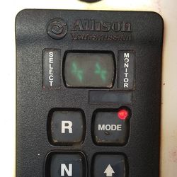
It just takes a little practice and to recognize which fault code system your vehicle has. For example for Allison transmissions there will be vehicles with a single digit entry for their fault codes.
For other vehicles, there will be a double digit readout and that should be easier to read. One thing to take note, we mentioned the letter D before but that seems to only stand for diagnostic come.
It will appear on both the single and double digit readouts in the first position. The reason for this is this code is telling you where in the fault code line up its position is.
For example if you see D then a 1 in the second box of the single digit readout, you are being told this is the first code in the line of codes that has been set. In the double digit readout this code should read D1 but with the D above the 1.
D2 followed by the code will tell you that it is the second code that has been set by the problem. To read the single digit code, and the readout may be vertical in your vehicle, you will see D1 13 12.
The first two digits are for the position of the code, first , second, third, and so on. The 13 tells you the main code and the 12 will tell you the sub code. In this example the problem is caused by ECU Input Voltage Low.
For the double digit code, you will see the D1 (or 2, etc). then the letter P (or C or U) by itself, then a pair of numbers vertically,, for example 07 then another pair of numbers 22 vertically.
That code would look like this- D1 P0722 and to find the meaning of this code you just look up P0722 which stands for- Output Speed Sensor, No Signal. That is how you read this code system.
Just be careful about the position of the numbers. They will go according to how your read out is set up in your vehicle.
How To Reset Allison Transmission Fault Codes
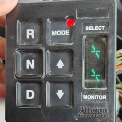
One way to do this., and there may be more than one depending on your Allison transmission model, you simply press the ‘Mode’ button and hold it. Keep holding it till you hear 2 beeps and then release the ‘Mode’ button.
Or if you have an older Allison transmission, the way to reset the transmission is to disconnect the battery cables for 30 seconds. This should clear all codes and give you a new start. You may have to clear the ECU as well and that only takes 10 seconds with the cables off.
If you own a newer Allison transmission, you may be restricted to using a code reader to reset the codes. It seems that a standard code reader you can get from the auto parts outlets will do the job here.
Just connect the reader to your diagnostic part of the transmission and then push the clear codes buttons.
Clearing Allison Transmission Codes
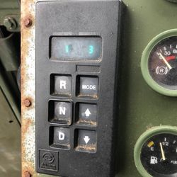
There are two sets of instructions. One is for the single digit readout and the other is for the double digit model. First the single digit read out:
1. Press and hold the ‘mode’ button for 3 seconds. The LED indicator light should start to flash. Release the mode button and the active codes should not be illuminated.
To clear inactive codes, you simply press and hold the ‘Mode’ button for 10 seconds. Some codes require engine cycling to clear and others are self-clearing.
2. Record all fault codes before you clear them. This will help your repair work go smoother.
3. Drive your vehicle around a little bit to see if any of the fault codes you cleared return or not. If they do return then take your vehicle to an authorized Allison transmission expert and have them fix the problem.
For the double digit display #2 and 3 are the same. It is just #1 that is different.
1. This step is very simple, just press the ‘Mode’ button for 10 seconds and both the active and inactive codes will be cleared.
That is all you have to do for the Allison 3000 and 4000 transmission series.
Some Additional Words
Now that you have the Allison transmission codes, you should be able to talk intelligently with the transmission repair man and understand what is wrong with this valuable part.
Also, with the right code reader you should be able to make your own diagnosis and see if you are able to make the repair yourself or not. Information is always king and when you have it, you are not at the mercy of the unethical repairmen.
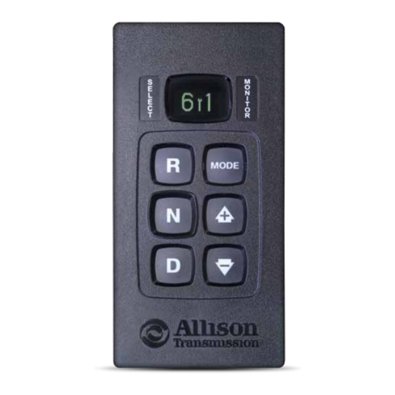
-
Contents
-
Table of Contents
-
Bookmarks
Quick Links
OPERATION
+ CODE MANUAL
SHIFT SELECTOR
OIL LEVEL INFORMATION, DIAGNOSTIC CODES AND PROGNOSTIC FEATURES
FOR 3000/4000 SERIES
AND TC10
ALLISON TRANSMISSIONS
™
™
Related Manuals for Allison Transmission shift selector
Summary of Contents for Allison Transmission shift selector
-
Page 1
OPERATION + CODE MANUAL SHIFT SELECTOR OIL LEVEL INFORMATION, DIAGNOSTIC CODES AND PROGNOSTIC FEATURES FOR 3000/4000 SERIES AND TC10 ALLISON TRANSMISSIONS ™ ™… -
Page 2: Table Of Contents
Table of Contents General Information . . . . . . . . . . . . . . . . . . . . . . . . . . . . . . . . . . . . . 1 Basic Operation .
-
Page 3: General Information
. Through readouts on your shift selector, you will be able to monitor transmission oil levels, read diagnostic codes and prognostic information . This manual will help you understand shift selector readouts and enjoy long, trouble-free operation of your Allison Automatic .
-
Page 4: Basic Operation
5th Generation Electronic Controls Shift Selectors As the world leader in medium- and heavy-duty commercial transmissions, Allison Transmission continues its ongoing improvement initiative with the introduction of 5th Generation Electronic Controls Shift Selectors . All 5th Generation Electronic Controls Shift Selectors feature easy-to-read graphic displays that show both text and symbols .
-
Page 5: Section 1 — With Prognostics + With Oil Level Sensor
1 . Park the vehicle on a level surface, shift to N (NEUTRAL) and apply the parking brake . 2 . Using a pushbutton shift selector, simultaneously press the UP and DOWN arrows one time . For a bump lever shift selector, press the DIAGNOSTICS button one time .
-
Page 6: Prognostic Features
4 . The shift selector displays the oil level data as follows: • CORRECT FLUID LEVEL – The fluid is within the correct fluid level zone when OK is shown . • LOW FLUID LEVEL – The display shows the number of quarts the transmission oil is low .
-
Page 7: Accessing Prognostics
The status of transmission health is displayed as OK or LO . Accessing Prognostics When you are alerted via the WRENCH ICON on the shift selector that service is due, you can check the status by toggling through the shift selector display as follows .
-
Page 8: Resetting Prognostics
MODE button for approximately 10 seconds while in Filter Life Monitor mode . For either a pushbutton or bump lever shift selector, perform the following shift sequence with the ignition on, but the engine off . Do not stop the sequence for more than three seconds once you have started .
-
Page 9: Diagnostics Codes
To exit the diagnostic code function: Any of the following methods may be used . 1 . For a pushbutton shift selector, press the N (NEUTRAL) range button . 2 . For a bump lever shift selector, press the DIAGNOSTICS range button until back to range display .
-
Page 10: Section 2 — With Prognostics + Without Oil Level Sensor
SECTION 2 WITH PROGNOSTICS + WITHOUT OIL LEVEL SENSOR Prognostic Features 5th Generation Electronic Controls Shift Selectors display prognostics in text form to provide at-a-glance status of Oil Life, Filter Life and Transmission Health . PUSHBUTTON The WRENCH ICON will illuminate briefly after you turn the key to the run position on your Allison-equipped vehicle to indicate that prognostics are enabled .
-
Page 11: Accessing Prognostics
Accessing Prognostics When you are alerted via the WRENCH ICON on the shift selector that service is due, you can check the status by toggling through the shift selector display as follows . Be sure to park the vehicle on a level surface, shift to N (NEUTRAL) and apply the parking brake before accessing prognostics through the shift selector.
-
Page 12: Resetting Prognostics
MODE button for approximately 10 seconds while in Filter Life Monitor mode . For either a pushbutton or bump lever shift selector, perform the following shift sequence with the ignition on, but the engine off . Do not stop the sequence for more than three seconds once you have started .
-
Page 13: Diagnostics Codes
To exit the diagnostic code function: Any of the following methods may be used . 1 . For a pushbutton shift selector, press the N (NEUTRAL) range button . 2 . For a bump lever shift selector, press the DIAGNOSTICS range button until back to range display .
-
Page 14: Section 3 — Without Prognostics + With Oil Level Sensor
1 . Park the vehicle on a level surface, shift to N (NEUTRAL) and apply the parking brake . 2 . Using a pushbutton shift selector, simultaneously press the UP and DOWN arrows one time . For a bump lever shift selector, press the DIAGNOSTICS button one time .
-
Page 15
4 . The shift selector displays the oil level data as follows: • CORRECT FLUID LEVEL – The fluid is within the correct fluid level zone when OK is shown . • LOW FLUID LEVEL – The display shows the number of quarts the transmission oil is low . -
Page 16: Diagnostics Codes
To exit the diagnostic code function: Any of the following methods may be used . 1 . For a pushbutton shift selector, press the N (NEUTRAL) range button . 2 . For a bump lever shift selector, press the DIAGNOSTICS range button until back to range display .
-
Page 17: Section 4 — Without Prognostics + Without Oil Level Sensor
To enter the diagnostic code function: 1 . Bring the vehicle to a complete stop . Apply the parking brake . 2 . For a pushbutton shift selector, simultaneously press the UP and DOWN arrows one time . For a bump lever shift selector, press the DIAGNOSTICS button one time .
-
Page 18
To exit the diagnostic code function: Any of the following methods may be used . 1 . For a pushbutton shift selector, press the N (NEUTRAL) range button . 2 . For a bump lever shift selector, press the DIAGNOSTICS range button until back to range display . -
Page 19
Diagnostic Transmission Codes DIAGNOSTIC CODE CODE DESCRIPTION P0122 PEDAL POSITION SENSOR CIRCUIT LOW VOLTAGE P0123 PEDAL POSITION SENSOR CIRCUIT HIGH VOLTAGE P0218 TRANSMISSION FLUID OVER TEMPERATURE CONDITION P0562 SYSTEM VOLTAGE LOW P057C BRAKE PEDAL POSITION SENSOR LOW P057D BRAKE PEDAL POSITION SENSOR HIGH P0602 TCM NOT PROGRAMMED P0603… -
Page 20
DIAGNOSTIC CODE CODE DESCRIPTION P0796 PRESSURE CONTROL SOLENOID (PCS) 3 STUCK OFF P0797 PRESSURE CONTROL SOLENOID (PCS) 3 STUCK ON P07D9 INCORRECT 8TH GEAR RATIO P07F6 INCORRECT 9TH GEAR RATIO P07F7 INCORRECT 10TH GEAR RATIO P081B CRANK ENABLE CIRCUIT HIGH P0837 FOUR WHEEL DRIVE (4WD) SWITCH CIRCUIT RANGE/PERFORMANCE P083C… -
Page 21
DIAGNOSTIC CODE CODE DESCRIPTION P0994 TRANSMISSION FLUID PRESSURE SWITCH 5 CIRCUIT LOW P0995 TRANSMISSION FLUID PRESSURE SWITCH 5 CIRCUIT HIGH P0995 TRANSMISSION FLUID PRESSURE SWITCH 5 CIRCUIT HIGH P0A0B HIGH VOLTAGE INTERLOCK LOOP 1 INVALID P0A2F DRIVE MOTOR OVER TEMPERATURE P0A44 DRIVE MOTOR OVERSPEED P0A7D… -
Page 22
DIAGNOSTIC CODE CODE DESCRIPTION P2641 TORQUE MANAGEMENT FEEDBACK SIGNAL B P2669 ACTUATOR SUPPLY CIRCUIT VOLTAGE 2 OPEN (HSD 2) P2670 ACTUATOR SUPPLY CIRCUIT VOLTAGE 2 LOW (HSD 2) P2671 ACTUATOR SUPPLY CIRCUIT VOLTAGE 2 HIGH (HSD 2) P2684 ACTUATOR SUPPLY CIRCUIT VOLTAGE 3 OPEN (HSD 3) P2685 ACTUATOR SUPPLY CIRCUIT VOLTAGE 3 LOW (HSD 3) P2686… -
Page 23
DIAGNOSTIC CODE CODE DESCRIPTION P281D PRESSURE CONTROL SOLENOID (PCS) 7 CONTROL CIRCUIT LOW P281E PRESSURE CONTROL SOLENOID (PCS) 7 CONTROL CIRCUIT HIGH P2824 PRESSURE CONTROL SOLENOID (PCS) 8 CONTROL CIRCUIT OPEN P2826 PRESSURE CONTROL SOLENOID (PCS) 8 CONTROL CIRCUIT LOW P2827 PRESSURE CONTROL SOLENOID (PCS) 8 CONTROL CIRCUIT HIGH P2832… -
Page 24
To order an Operator’s Manual, go to allisontransmission.com or call toll free 888-666-5799 . One Allison Way SA7497EN (2014/10) Indianapolis, Indiana, USA 46222-3271 ISO/QS 9000 and ISO 14001 Certified Information or specifications subject to © 2014 Allison Transmission Inc. change without notice or obligation. All rights reserved. allisontransmission.com…
![]()
Автоматические коробки передач
Allison 3000 и 4000 Серии
с электронным управлением Gen4.
Руководство по эксплуатации и обслуживанию
АКПП Allison 3000 и 4000 cерий
с 2006 модельного года.
Электронное управление Gen4.
125373, Россия, Москва,
Походный проезд, д. 4, стр. 1, 2 этаж, офис 207.
Тел./факс: (495) 223-65-69
E-mail: allison@ndgs.ru или moscow@ndgs.ru
www.ndgs.ru
|
Автоматические коробки передач |
|||
|
Allison 3000 и 4000 Серии |
|||
|
с электронным управлением Gen4. |
|||
|
Содержание |
|||
|
0. Условия использования руководства и ограничение ответственности……………….. |
4 |
||
|
1. Общее описание………………………………………………………………………………………………. |
5 |
||
|
1.0.1 Вид АКПП 3000 Серии…………………………………………………………………………… |
6 |
||
|
1.0.2 Вид АКПП 3000 Серии с ретардером……………………………………………………… |
7 |
||
|
1.0.3 Паспортная табличка АКПП…………………………………………………………………… |
8 |
||
|
1.1 Электронная система управления………………………………………………………………… |
8 |
||
|
2. Эксплуатация АКПП……………………………………………………………………………………….. |
10 |
||
|
2.0.1 Общие указания по эксплуатации…………………………………………………………… |
10 |
||
|
2.1 Переключение передач………………………………………………………………………………… |
11 |
||
|
2.1.1 Элементы переключателя передач………………………………………………………….. |
11 |
||
|
2.1.1.1 Цифровой дисплей……………………………………………………………………………. |
11 |
||
|
2.1.1.2 Кнопка режима «MODE» ………………………………………………………………….. |
12 |
||
|
2.1.1.3 Светодиод включения дополнительного режима……………………………….. |
12 |
||
|
2.1.1.4 Кнопка меню (только для рычажного переключателя)……………………….. |
12 |
||
|
2.1.2 Выбор режима кнопочным переключателем…………………………………………… |
13 |
||
|
2.1.3 Положения рычажного переключателя…………………………………………………… |
14 |
||
|
2.2 Другие элементы управления и контроля……………………………………………………… |
15 |
||
|
2.2.1 Контрольная лампа нарушения нормальной работы «Check Trans»…………. |
15 |
||
|
2.2.2 Контрольная лампа температуры масла АКПП……………………………………….. |
15 |
||
|
2.2.3 Указатель температуры масла АКПП……………………………………………………… |
15 |
||
|
2.2.4 Управление ретардером (опция)……………………………………………………………… |
15 |
||
|
2.2.4.1 Аккумулятор ретардера…………………………………………………………………….. |
16 |
||
|
2.3 Движение……………………………………………………………………………………………………. |
16 |
||
|
2.3.1 Порядок переключения передач……………………………………………………………… |
16 |
||
|
2.3.2 Движение на спусках……………………………………………………………………………… |
17 |
||
|
2.3.3 Торможение двигателем…………………………………………………………………………. |
17 |
||
|
2.3.4 Торможение ретардером………………………………………………………………………… |
18 |
||
|
2.3.5 Предохранительные функции…………………………………………………………………. |
18 |
||
|
2.3.5.1 Защита от перекрутки двигателя и включения слишком низкой |
|||
|
передачи…………………………………………………………………………………………… |
18 |
||
|
2.3.5.2 Блокировка включения передачи………………………………………………………. |
18 |
||
|
2.3.5.3 Влияние температуры масла АКПП и ретардера на |
|||
|
переключение передач………………………………………………………………………. |
19 |
||
|
2.3.6 Дополнительные функции………………………………………………………………………. |
20 |
||
|
2.3.6.1 «Быстрая нейтраль» для мусоровозов………………………………………………… |
20 |
||
|
2.3.6.2 Блокировка движения для пожарных машин и спецтехники………………. |
20 |
||
|
2.3.6.3 Выходной сигнал скорости……………………………………………………………….. |
21 |
||
|
2.4 Меры при буксировке автомобиля……………………………………………………………….. |
21 |
||
|
2.4.1 Запуск двигателя буксировкой……………………………………………………………….. |
21 |
||
|
2.4.2 Буксировка с выключенным двигателем…………………………………………………. |
21 |
||
|
2.5 Диагностика ошибок……………………………………………………………………………………. |
22 |
||
|
2.5.1 Считывание кодов ошибок……………………………………………………………………… |
22 |
||
|
3. Обслуживание…………………………………………………………………………………………………. |
23 |
||
|
Руководство по эксплуатации и обслуживанию Allison 3000/4000 Gen4. |
2 |
||
|
ООО «НДГС» |
Тел/факс: +7 (495) 223-65-69 |
www.ndgs.ru |
Автоматические коробки передач
Allison 3000 и 4000 Серии
с электронным управлением Gen4.
|
3.1 |
Контроль уровня масла……………………………………………………………………………….. |
23 |
|
3.1.1 Проверка уровня масла посредством масляного щупа…………………………….. |
23 |
|
|
3.1.2 Проверка уровня масла через переключатель передач…………………………….. |
23 |
|
|
3.2 |
Применяемые масла…………………………………………………………………………………….. |
27 |
|
3.3 |
Периоды замены масла и фильтров …………………………………………………………….. |
26 |
|
3.4 |
Краткая информация по маслам…………………………………………………………………… |
27 |
|
3.5 |
Необходимые объемы масла………………………………………………………………………… |
27 |
|
3.6 |
Фильтры……………………………………………………………………………………………………… |
28 |
|
3.7 |
Замена фильтров и масла……………………………………………………………………………… |
28 |
|
3.7.1 Слив масла…………………………………………………………………………………………….. |
29 |
|
|
3.7.2 Замена фильтров……………………………………………………………………………………. |
29 |
|
|
3.7.3 Заполнение маслом………………………………………………………………………………… |
29 |
|
|
4. Диагностика ошибок………………………………………………………………………………………… |
30 |
|
|
4.1 Считывание кодов ошибок…………………………………………………………………………. |
30 |
|
|
4.2 Коды ошибок…………………………………………………………………………………………….. |
31 |
|
|
4.2.1 Сокращения…………………………………………………………………………………………. |
31 |
|
|
4.2.2 Таблица кодов ошибок…………………………………………………………………………. |
31 |
|
|
5. Контакты…………………………………………………………………………………………………………. |
37 |
|
Руководство по эксплуатации и обслуживанию Allison 3000/4000 Gen4. |
3 |
||
|
ООО «НДГС» |
Тел/факс: +7 (495) 223-65-69 |
www.ndgs.ru |
Автоматические коробки передач
Allison 3000 и 4000 Серии
с электронным управлением Gen4.
0. Условия использования руководства и ограничение ответственности
Представленный печатный документ и приводимая в нем информация служат как базисный материал для курсов обучения в НДГС и DGS Diesel- &Getriebeservice GmbH.
Целью обучения является ознакомление с конструкцией и возможностями охватываемых руководством АКПП. Приводимая информация не претендует на полноту и не подлежит автоматическому обновлению при внесении изменений в конструкцию. Учет изменений производится только при переработке издания автором.
Самую последнюю информацию можно найти в соответствующих публикациях Allison Transmission. В разделе литература представлен список изданий Allison Transmission.
Также можно зайти на сайт www.allisontransmission.com
ООО «НДГС», DGS Diesel- &Getriebeservice GmbH и Allison Transmission не несут ответственности за любой ущерб, возникший от использования данного руководства.
Содержимое данного издания и приводимая информация защищены авторскими правами. Копирование, распространение и частичное или полное воспроизведение без письменного разрешения DGS или Allison Transmission не допускаются.
|
Руководство по эксплуатации и обслуживанию Allison 3000/4000 Gen4. |
4 |
||
|
ООО «НДГС» |
Тел/факс: +7 (495) 223-65-69 |
www.ndgs.ru |
Автоматические коробки передач
Allison 3000 и 4000 Серии
с электронным управлением Gen4.
1. Общее описание
Автоматические трансмиссии Allison 3000 и 4000 Серии – полностью автоматические коробки передач, использующие самые современные технологии с электронной системой управления с шестью (или семью) передачами вперед и одной назад.
|
Серия 3000 |
|
|
Макс. мощность |
298 кВт |
|
Макс. момент |
1695 Нм |
|
Серия 4000 |
|
|
Макс. мощность |
447 кВт |
|
Макс. момент |
2576 Нм |
Приведенные параметры зависят от применения АКПП (типа транспортного средства). Чтобы получить точные спецификации, обратитесь в ООО «НДГС» или зайдите на сайты www.ndgs.ru или www.allisontransmission.com
Для всех серий имеются различные модификации:
Модификация с возможностью установки КОМ.
Модификация с ретардером.
Автобусная модификация.
Все модельные ряды построены по общему принципу:
На входе АКПП стоит гидротрансформатор с функцией блокирования (Lock-Up) и встроенным демпфером крутильных колебаний.
После гидротрансформатора следуют косозубые планетарные ряды, организованные по запатентованной схеме, позволяющие плавно переключать передачи без разрыва потока мощности.
Автоматическое переключение управляется электронной системой на основе следующих входных данных:
Положение переключателя передач – Информация о выбранном водителем режиме
Частота вращения выходного вала – Информация о скорости автомобиля
Положение педали акселератора – Информация о режиме работы двигателя
На АКПП может быть установлено до двух отборов мощности
На выходе может быть установлен ретардер
|
Руководство по эксплуатации и обслуживанию Allison 3000/4000 Gen4. |
5 |
||
|
ООО «НДГС» |
Тел/факс: +7 (495) 223-65-69 |
www.ndgs.ru |
Автоматические коробки передач
Allison 3000 и 4000 Серии
с электронным управлением Gen4.
1.0.1 Вид АКПП 3000 Серии
|
Руководство по эксплуатации и обслуживанию Allison 3000/4000 Gen4. |
6 |
||
|
ООО «НДГС» |
Тел/факс: +7 (495) 223-65-69 |
www.ndgs.ru |
Автоматические коробки передач
Allison 3000 и 4000 Серии
с электронным управлением Gen4.
1.0.2 Вид АКПП 3000 Серии с ретардером
|
Руководство по эксплуатации и обслуживанию Allison 3000/4000 Gen4. |
7 |
||
|
ООО «НДГС» |
Тел/факс: +7 (495) 223-65-69 |
www.ndgs.ru |
Автоматические коробки передач
Allison 3000 и 4000 Серии
с электронным управлением Gen4.
1.0.3 Паспортная табличка
При заказе запасных частей или при решении технических вопросов, а также при проведении гарантийного ремонта, потребуется серийный номер АКПП.
На паспортной табличке можно найти следующую информацию:
Производитель и завод-производитель
Дата выпуска
Идентификационный номер АКПП Allison
Идентификационный код АКПП
Модель АКПП
10-значный серийный номер АКПП
Пример сверху
06F27
E012578
TID A 3000SP 6520062608
1.1 Электронная система управления
С 2005 модельного года АКПП 3000 и 4000 Серии оснащаются электронной системой управления Allison 4-го поколения (сокращенно Gen4).
Постоянные улучшения и расширения возможностей системы позволяют добавлять новые функции.
Система состоит из следующих компонентов:
Блок управления АКПП (TCM=»Transmission Control Module»);
Три датчика частоты вращения: коленвала двигателя, турбины, выходного вала
АКПП;
Электронный переключатель передач;
|
Руководство по эксплуатации и обслуживанию Allison 3000/4000 Gen4. |
8 |
||
|
ООО «НДГС» |
Тел/факс: +7 (495) 223-65-69 |
www.ndgs.ru |
Автоматические коробки передач
Allison 3000 и 4000 Серии
с электронным управлением Gen4.
Электрогидравлический блок управляющих клапанов.
Блок управления обрабатывает информацию различных датчиков, а также информацию от других систем автомобиля и подаёт сигналы на электромагнитные клапаны для переключения передач.
Блок управления отслеживает скорости вращения выходного вала, коленвала двигателя и турбинного колеса, а также температуру и давление масла. При нарушении нормальной работы в памяти TCM сохраняются коды ошибок, которые можно считать с дисплея переключателя передач.
Электронная система управления отвечает также за отбор мощности, ретардер и другие функции такие, как торможение двигателем, защита от превышения оборотов, блокировка включения передач, «быстрая нейтраль».
Электронная система управления Gen4 совместима с протоколом связи CAN и может обмениваться информацией с другими системам автомобиля.
|
Руководство по эксплуатации и обслуживанию Allison 3000/4000 Gen4. |
9 |
||
|
ООО «НДГС» |
Тел/факс: +7 (495) 223-65-69 |
www.ndgs.ru |
Автоматические коробки передач
Allison 3000 и 4000 Серии
с электронным управлением Gen4.
2. Эксплуатация АКПП
2.0.1 Общие указания по эксплуатации
Почему полностью автоматическая трансмиссия?
На Вашем автомобиле установлена АКПП Allison 3000/4000 Серии. Эта полностью автоматическая трансмиссия с электронным управлением, использующая самые современные технологии, облегчает управление Вашим коммерческим транспортным средством в тяжелых уличных условиях. В особенности при коротких перевозках в режиме частых остановок автоматическая трансмиссия оказывается оптимальной.
Краткое описание
АКПП имеет в зависимости от конструкции и программы управления 4, 5, 6 или 7 передач вперед и 1 назад.
В качестве муфты включения и отключения АКПП служит гидротрансформатор со встроенным механизмом блокировки, который автоматически блокирует гидротрансформатор в движении и разблокирует при остановках. Гидротрансформатор обеспечивает высокий крутящий момент и плавность при трогании, а механизм блокировки
– экономию топлива.
АКПП спроектирована для удобного обслуживания. Ознакомьтесь, пожалуйста, с руководством по техническому обслуживанию.
Для оптимального переключения передач и повышения срока жизни АКПП, всегда следите за следующим:
|
Несколько советов (базовых правил) по эксплуатации АКПП |
|||||
|
! |
Перемену направления движения производить только при остановке автомобиля |
||||
|
и холостых оборотах двигателя. |
|||||
|
Используйте стояночный тормоз только при холостых оборотах двигателя. |
|||||
|
Следите за тем, чтобы в режиме Drive ручной газ и повышение оборотов |
|||||
|
двигателя были выключены. |
|||||
|
! |
Не допускайте движения автомобиля на нейтральной передаче |
||||
|
! |
На светофоре или в аналогичных ситуациях не выключайте передачу. |
||||
|
Включайте нейтраль только при остановках более 5 минут. |
|||||
|
Не допускайте работу двигателя более 5 минут при стоянке автомобиля и |
|||||
|
включенной передаче. |
|||||
|
Если вы покидаете автомобиль, включайте нейтраль. |
|||||
|
! |
Следите за уровнем масла в АКПП |
||||
|
Соблюдайте периоды обслуживания |
|||||
|
Руководство по эксплуатации и обслуживанию Allison 3000/4000 Gen4. |
10 |
||||
|
ООО «НДГС» |
Тел/факс: +7 (495) 223-65-69 |
www.ndgs.ru |
![]()
Автоматические коробки передач
Allison 3000 и 4000 Серии
с электронным управлением Gen4.
2.1 Переключение передач
Переключатель передач может быть выполнен в виде кнопочной панели или рычага. Оба варианта электронные.
Как специальный вариант есть упрощенные кнопочные панели. Эти панели сохраняют все функции управления, однако на них отсутствует возможность диагностики и проверки уровня масла, поскольку отсутствует дисплей.
2.1.1 Элементы переключателя передач
2.1.1.1 Цифровой дисплей
Переключатель передач имеет двухэлементный цифровой дисплей
Показания при движении
Во время нормальной работы на дисплее отображается два значения. Слева отображается высшая достигаемая передача. В нормальных условиях она определяется положением рычага переключателя передач или задается кнопочным переключателем. Справа на дисплее отображается текущая передача.
При активировании дополнительной функции АКПП может автоматически выбирать передачу, отличающуюся от выбранной водителем. Так, например, при торможении двигателем включается 2-ая передача.
При включении некоторых функций, а также для защиты АКПП в некоторых случаях может быть заблокировано включение передачи. В этом случае независимо от выбора передачи справа будет показана нейтральная передача N. Для снятия блокировки требуется выключить дополнительные функции или устранить причину блокировки.
Показания при нарушении работы
Если жидкокристаллический дисплей полностью высвечен более 12 секунд, это означает, что ему не удалось подключиться к системе управления. Выключите зажигание и включите снова.
|
Руководство по эксплуатации и обслуживанию Allison 3000/4000 Gen4. |
11 |
||
|
ООО «НДГС» |
Тел/факс: +7 (495) 223-65-69 |
www.ndgs.ru |
Автоматические коробки передач
Allison 3000 и 4000 Серии
сэлектронным управлением Gen4.
Если дисплей не горит и в обоих полях через 10 сек. появляются прочерки, подключение к блоку управления нарушено или имеется код ошибки.
Если дисплей не горит вообще, проверьте его подключение.
При ошибках, включающих диагностическую лампу «Check Trans», в поле выбранной передачи ничего не горит, а справа отображается текущая передача.
Если при движении возникает критическая ошибка, управление не реагирует на выбранную передачу, и АКПП остается на включенной в текущий момент передаче, пока двигатель не будет остановлен и зажигание выключено. После этого в случае критической ошибки АКПП будет оставаться в нейтрали, пока не будет устранена причина ошибки.
Показания в режиме диагностики
В режиме проверки уровня масла будет показан код уровня масла.
В режиме диагностики отображаются сохраненные (прошлые) и текущие (активные) коды ошибок.
2.1.1.2 Кнопка режима «MODE»
(«Mode» = Режим) Кнопка режима Mode выполняет две функции:
Кнопкой режима включается запрограммированная дополнительная функция. Для контроля включения режима загорается светодиод. В большинстве случаев дополнительный режим — это особый (например, экономичный) режим переключения передач.
Примеры дополнительных режимов:
«Динамика» — переключение происходит на высоких оборотах двигателя, используется вся его мощность
«Экономия» — двигатель работает в пределах оборотов обеспечивающих наибольшую экономичность.
В режиме диагностики ошибок кнопка Mode переключает сохраненные коды ошибок
2.1.1.3 Светодиод включения дополнительного режима
На кнопке Mode находится красный светодиод. Включение этого диода может означать две вещи:
При нормальной работе это означает, что включен второй режим.
В режиме диагностики, — что отображаемый код ошибки является активным (причина ошибки не устранена)
2.1.1.4 Кнопка меню (только для рычажного переключателя)
Проверка уровня масла и диагностика
Проверка уровня масла (нажать 1 раз)
Диагностика (нажать 2 раза)
При кнопочном переключателе эти функции вызываются соответствующим нажатием
|
одновременно двух стрелочных кнопок. |
|||
|
Руководство по эксплуатации и обслуживанию Allison 3000/4000 Gen4. |
12 |
||
|
ООО «НДГС» |
Тел/факс: +7 (495) 223-65-69 |
www.ndgs.ru |
Loading…
Diagnostic Codes
To enter the diagnostic code function:
1 . Bring the vehicle to a complete stop .
Apply the parking brake .
2 . For a pushbutton shift selector, simultaneously press
the UP and DOWN arrows five times (four times for TC10) .
For a bump lever shift selector,
press the DIAGNOSTICS button five times .
3 . Up to five codes may be recorded in memory .
4 . Each code remains in the display until the MODE button is pushed, then
the next code is shown . Active codes are shown first, newest to oldest,
followed by any inactive codes still in the memory .
ACTIVE CODES:
For a detailed list of Diagnostic Transmission Codes for 5th Generation
Electronic Controls Shift Selectors, see pages 17 through 21 .
To exit the diagnostic code function:
Any of the following methods may be used .
1 . For a pushbutton shift selector, press the N (NEUTRAL)
range button .
2 . For a bump lever shift selector, press the DIAGNOSTICS
range button until back to range display .
3 . Wait approximately 10 minutes and the system will
automatically return to normal operating mode .
4 . Turn off the vehicle engine ignition switch .
Drive the vehicle and check for code recurrence . If codes continue to
recur, bring the vehicle to an Allison Authorized Service Network to
diagnose and repair the problem causing the codes .
INACTIVE CODES:
7