
Теория конечных элементов не является единственным методом расчета мостовых конструкций, но существуют тенденции к использованию определенных методов и типов конечных элементов. Как правило, при моделировании мостов используются конечные элементы различного типа: соединения (узлы), линейные элементы (балки, ферменные элементы, кабели), двумерные элементы (плиты, оболочки) и трехмерные (объемные) элементы. При этом первые используются чаще. Несмотря на то, что линейные модели являются наиболее частыми в употреблении, во многих случаях используются основные нелинейные параметры, например:
Связи, работающие только на сжатие, для моделирования опирания на грунт
Данный тип нелинейности обычно требует специальной конфигурации моделирования вариантов нагрузки, поскольку опрокидывающие нагрузки могут привести к отсутствию сходимости решения модели. Поэтому, если необходимо выполнить расчет, удерживающие и опрокидывающие нагрузки следует объединить.

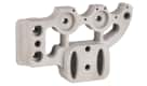
Рис. 1. Пружины, работающие только на сжатие, в модели крайней опоры моста
Зависящие от времени свойства материалов
В бетоне зависящие от времени свойства материала используются для моделирования реологических свойств: ползучести и усадки, а также изменения модуля упругости. В высокопрочной стали предварительно напряженных мостов они используются для отражения релаксации стали.
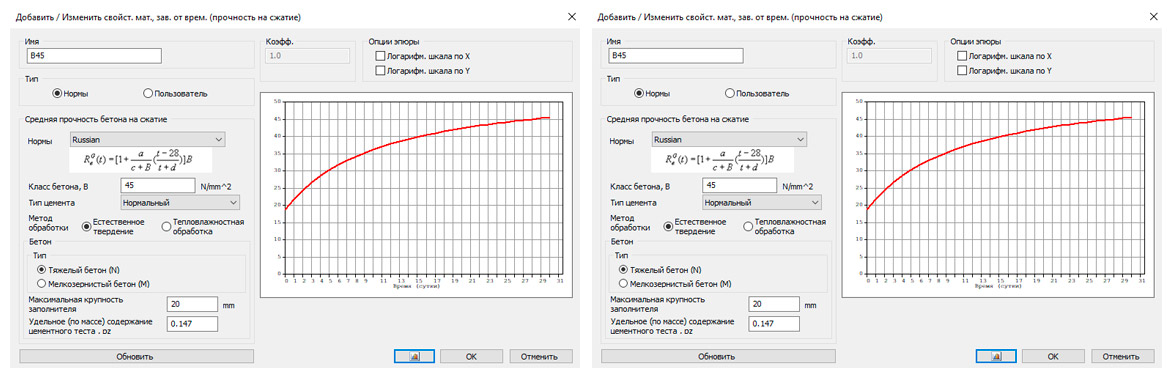
Рис. 2. Зависящие от времени реологические свойства бетона: ползучесть и усадка (слева), и прочность на сжатие (справа)
Данный тип нелинейности не требует наличия специального сочетания нагрузок, но учитывает другие характеристики, такие как шаг по времени и возраст бетона.
При моделировании мостов важно учитывать:
-
Специальные граничные условия для осуществления связей между элементами.
-
Конфигурации сетки и параметров расчета, специально разработанных для подвижных нагрузок.
-
Явное или неявное освобождение степеней свободы для моделирования ожидаемого поведения определенных элементов конструкции, таких как раскосы, связи и прочие элементы жесткости.
Типовые ошибки при моделировании мостов
Опоры пролетного строения

Рис. 3. Различные местоположения оси балочного элемента линейно-неподвижной опоры
Опирание многих элементов конструкций мостов располагают не на уровне центра тяжести поперечного сечения элемента, а на его нижней грани. Это относится к большинству пролетных строений, и те, в свою очередь, передают нагрузки на опорные элементы моста.
Эффект от опоры в точках, отличных от центра тяжести поперечного сечения, представляет собой незначительный момент, создаваемый эксцентриситетом реакции. Балка имеет возможность поворота в опоре, но эксцентриситет фактической опоры в нижней поверхности балки производит горизонтальное усилие, которое, в свою очередь, вызывает момент в балке. Поэтому не редкость наблюдать незначительные отрицательные моменты, даже когда опирание пролетного строения соответствует простой линейно-неподвижной опоре:

Рис. 4. Диаграмма тела свободного вращения балки
Распространенная ошибка — думать, что этих незначительных отрицательных моментов быть не должно, и искать способы их устранения, тогда как это именно то, чего и следует ожидать в соответствии с приведенными выше причинами.

Рис. 5. Незначительный отрицательный момент вблизи опоры балки
Так, при проведении проверок в программном комплексе midas Civil элементы с незначительным отрицательным моментом будут проверены на отрицательный изгиб. Тем не менее, иногда в конструкции не назначается армирование для восприятия отрицательного изгибающего момента, так как не предполагалось возникновение данных моментов. Таким образом, программа сообщит инженеру, что такое армирование необходимо. Инженер может выбрать один из вариантов:
- Игнорировать данное сообщение с учетом того, что отрицательный момент незначителен, близок к нулю.
- Предусмотреть армирование для восприятия отрицательного момента, которое обычно будет воспринимать усадочные деформации и температурные напряжения в плите балки. Это обеспечит достаточную изгибную прочность, как правило, большую, чем это требуется в данном расчетном случае.
Еще одной дополнительной переменной, которая может увеличить величину отрицательного момента, является жесткость упругой опорной части, если этот элемент используется. Жесткость такой опорной части мала, если ее сравнивать с несущими элементами в модели, поэтому она увеличит отрицательный момент. Для получения дополнительной информации о том, как рассчитать жесткость упругой опорной части обращайтесь в портал Технической Поддержки.
Отсутствие сходимости решения при использовании нелинейных граничных условий, например, связи работающие только на сжатие
Этот пример был рассмотрен в первой главе. Если удерживающие и опрокидывающие нагрузки не скомбинированы, то midas Civil, вероятно, укажет на отсутствие сходимости:

Рис. 6. Предупреждающее сообщение, которое указывает на отсутствие сходимости в программе midas Civil
В таких случаях инженеру следует помнить, что в программах обычно решают уравнения равновесия не для сочетаний нагрузок, а для вариантов нагрузки (как в программе midas Civil). Таким образом, равновесие может быть достигнуто только в том случае, если в каждом варианте нагрузки рассматриваются удерживающие и опрокидывающие нагрузки одновременно. Другими словами, сочетание нагрузок должно быть задано в виде варианта нагрузок. Если равновесия и в таком случае не удается достигнуть, это, по всей видимости, означает, что конструкция в действительности имеет проблемы со стабильностью.

Рис. 7. Сочетания нагрузок, преобразованные в варианты нагрузок для нелинейного расчета в программе midas Civil
Отсутствие сходимости при использовании конечных элементов с освобождением степеней свободы
Всегда сложно использовать, явно или неявно, элементы с освобожденными степенями свободы. Это делается явно в случаях, когда, например, балочный элемент не обладает вращательной жесткостью на концах. Неявно, когда вместо выполнения вышеуказанного используется ферменный элемент, работающий только на растяжение или сжатие, или кабельный элемент — только на растяжение.
Во многих случаях расчет подобных моделей не сходится, поскольку многие степени свободы были освобождены, и таким образом модель оказывается нестабильной. В таком случае достаточно сделать простой расчет траекторий нагрузки и убедиться, что для любого из конечных элементов или модели в целом конструкция является стабильной.


Рис. 8. Два разных линейных элемента: балочный (слева) и тросовый (справа)
Отсутствие сходимости при расчете мостов с учетом стадий возведения
Если модель учитывает переменный модуль упругости бетона, зависящий от времени, то все части конструкции должны активироваться при модуле упругости, значение которого превышает нуль. В противном случае это приведет к нулевой жесткости и, следовательно, проблемам сходимости решений. Такое поведение можно обнаружить, наблюдая деформации конструкции на каждом этапе возведения или пытаясь с целью оценки активировать и деактивировать переменные свойства. В таком случае проблема может быть решена путем активации элемента, при возрасте бетона больше нуля.

Рис. 9. Чрезмерные деформации ригеля при задании нулевого модуля упругости в стадийном возведении
В большинстве случаев инженер определяет размеры шага по времени на стадии возведения в соответствии с основными этапами возведения, например, бетонирование и монтаж балок, бетонирование и монтаж плит и т. д. Тем не менее, при использовании материалов, зависящих от времени, всегда важно обеспечить адекватные размеры шага по времени. На приведенном ниже графике выделенную часть кривой можно принять неправильно при недолжном размере шага по времени, как указано:

Рис. 10. Недостаточный шаг по времени для расчета зависящих от времени материалов.
В программе midas Civil это, как правило, не является проблемой, так как существуют внутренние правила для учета меньших шагов по времени при использовании материалов, зависящих от времени.
Если трудности сходимости в модели, использующей стадии возведения, не обусловлены свойствами бетона, необходимо убедиться, что граничные условия активируются в нужное время.
Для проверки достаточно быстрой визуализации всех стадий при включении активируемых опор. Обнаружить, что конструкции необходимо дополнительное граничное условие, достаточно просто. В этом также помогает отслеживание сообщений об ошибках при расчете для определения точной стадии возведения, на которой возникает проблема. Такая функция предусмотрена в midas Civil.
Части конструкции не соединены в деформированной схеме, но не в базовом виде
Если модель показывает, что конструкция не соединена только в том случае, когда наблюдаются результаты деформаций, это, скорее всего, означает, что соответствующие конечные элементы на самом деле не соединены между собой.
Во многих случаях, когда были импортированы DXF-файлы с базовой геометрией конструкции, есть вероятность того, что конструкция не будет являться соединенной: из-за чертежной ошибки появляются два близких, но не зависимых друг от друга узла. Эту ошибку трудно обнаружить в недеформированном виде конструкции из-за близости таких узлов. В таком случае будет достаточно объединить узлы при помощи таких инструментов, как «Объединение дублирующих узлов».
Эта же ошибка может возникнуть в том случае, когда сетка конструкции была выполнена вручную, и ею игнорируется разделение существующих элементов в местоположении новых узлов. В этом случае просто используйте такие инструменты, как «Сжать». Благодаря сжатию геометрии конечных элементов вы можете наблюдать, какие узлы связаны, а какие нет. Если программа не выполняет сжатие элементов в определенном узле, то, вероятно, следует выполнить пересечение конечного элемента в этом положении.

Рис. 11. Использование функции «Сжатие» для коррекции несоединенных элементов.
Рекомендации
В дополнение к приведенным выше рекомендациям по исправлению часто возникающих ошибок, вы также можете следовать некоторым общим рекомендациям, чтобы избежать ошибок или быстро их исправить:
- Начните с простых моделей и постепенно увеличивайте сложность по мере необходимости.
- Модели следует проверять на каждом шаге разработки, при добавлении любых новых данных. Не стоит проверять лишь итоговую модель, так как источников ошибок может стать больше.
- Следуйте примеру моделирования, которые разбираются на вебинарах midas Civil. При этом всегда руководствуйтесь инженерной компетенцией, чтобы гарантировать целесообразность применения тех или иных решений.
Question:
When I try to run the analysis, I am getting: «[Error] Spacing must be greater than 0». I have no idea as to what spacing it is referring to.
Answer:
The cause was one of the vehicle definitions. The first user-defined vehicle is somehow interfering with the initial checks. I just deleted it and redefined a similar vehicle (Train) as the last vehicle. Now it’s not reporting any error.
Question:
Hi,
I have this error message on my computer when i run the attached model.
Note that my colleague has no problem running the analysis with his laptop.
The model was created with MIDAS Civil 2018 and i run the analysis with my recently upgraded to version 2019. I ran it with 2018 version before and it had the same error problem.
The problem seems to be with my computer? Please advise what could be the source of the problem?
Thanks & Regards,
Answer:
Hi,
Before we have a web session, here is one more thing you should try. Sometimes this is happening because anti-virus software does not allow midas Civil to write temporary files on the harddisk. Please turn off your anti-virus software and run midas Civil or you can add midas Civil to the list of safe software from your anti-virus software. Please let me know if it works or not.
Regards,
DK Lee
Table of Contents
1. Finite Element Modeling of Bridges
2. Common Errors and Discussion
3. Recommendations
1. Finite Element Modeling of Bridges
Finite element theory is not exclusive to the area of bridges, but there are tendencies to use certain techniques and types of finite elements in this area of structural engineering. Usually, in bridge modeling, finite element capabilities of an intermediate level of complexity are used, encompassing modeling with elements like joints (nodes), lines (frames, trusses, cables, etc.), surfaces (plates, membranes, etc.), and volumes (solids), being the firsts more frequently used than the latter. Although linear models are also frequent, on many occasions basic non-linear characteristics are used, for example:
Compression-only springs, to represent ground support
This type of nonlinearity usually requires a special modeling configuration for the load cases because destabilizing loads can lead to non-convergence of the solution of the model. Then, stabilizing and destabilizing loads should be combined before the analysis, if performed.
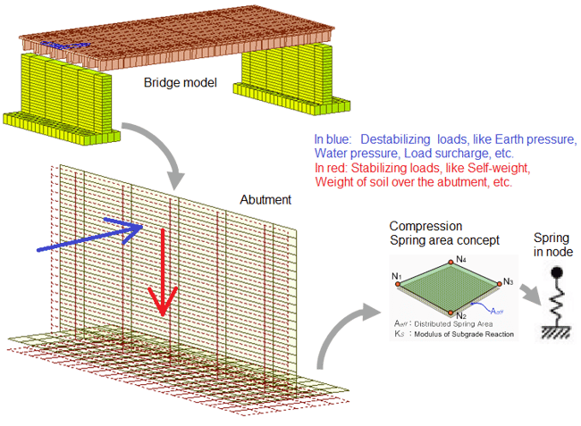
Figure 1. Compression-only springs in a numeric model of a bridge abutment
Time-dependent properties of materials
In concrete, time-dependent properties are used to capture the effects of plastic flow, shrinkage, and modulus of elasticity. In high-strength steel for prestressed bridges, they are used to reflect the relaxation of the steel.
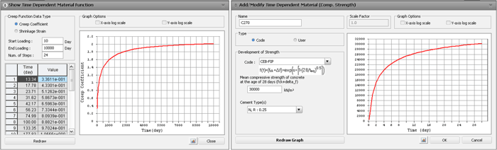 Figure 2. Time-dependent variables of concrete: creep and shrinkage (left) and compressive strength (right)
This type of nonlinearity does not require a combination of stabilizing and destabilizing loads for the analysis, but other considerations like time step size and concrete age take importance.
Other Concepts
- Analysis by construction stages, which are essentially non-linear analyzes since the stiffness of the structure changes from stage to stage.
- Geometric non-linearity, especially to analyze very flexible bridges such as those supported by cables, both due to the deformations of the structure in general and the great non-linearity of the cables themselves.
Features like the last one may not be basic, but programs such as midas Civil, focused on bridges, make it easier to perform this type of analysis by having features and functions that allow them to configure and streamline the representation in the numerical model.
In bridges, other special modeling concepts are important:
- Special boundary conditions to represent connections between elements.
- Meshing and analysis configurations specifically designed for moving loads.
- Releases of the degrees of freedom explicitly or implicitly for the expected real behavior of certain structural members such as braces or stiffeners.
2. Common Errors and Discussion
The following are some frequent errors and mistakes made in finite element modeling of bridges:
- Supports of the superstructures
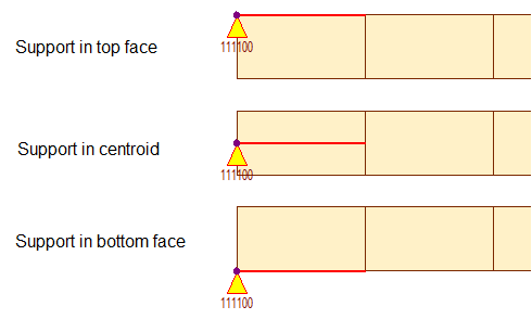 Figure 3. Different locations of beam for a simple pin support
Unlike buildings, many structural members of bridges do not rest on the centroid of other elements but on the lower faces. This is the case of most superstructures, for example, beams bearing in reinforced elastomers, and these, in turn, transmit the loads towards the substructure.
An effect of the support at points other than the centroid is the small moment generated by the eccentricity of the reaction. The beam needs to rotate in the support, but the eccentricity of the actual support in the bottom face of the girder produces a horizontal force, which in turn, produces a reaction moment in the girder, so it is not uncommon to see small negative moments even when the superstructure corresponds to a simple pin support:
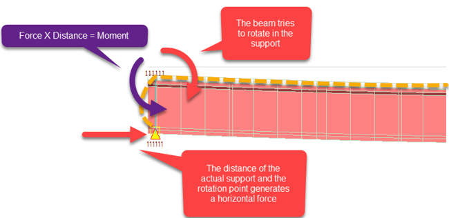 Figure 4. Free body diagram of the rotation of a beam with elastomeric bearings
It is a common mistake to think that these small negative moments should not exist and to look for ways to eliminate them when it really is something that is expected according to the reasons given.
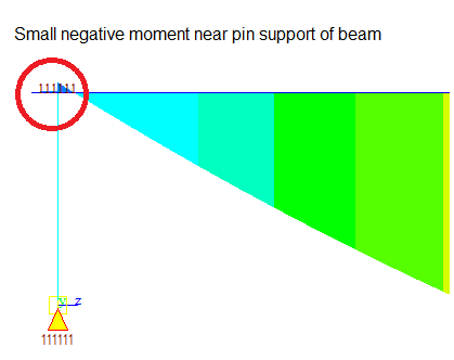
Figure 5. Small negative moment near support of beam with elastomeric bearings
When the design verification is to be performed in the program, for example in midas Civil, the elements with the small negative moment will be verified for negative flexure. Sometimes, however, no negative flexural reinforcement is assigned because no negative moment was expected, so the program will indicate that this reinforcement is required. The engineer has two options:
1. Disregard the message under the fact that the negative moment is very small, close to zero.
2. Include some negative moment reinforcement that will usually correspond to the shrinkage and temperature reinforcement in the top face of the girder. This will provide enough flexural strength, usually much more than that required in this context.
One additional variable that can increase the magnitude of the negative moment is the stiffness of the elastomeric bearing when this type of element is used. When compared to the connected elements in the model, the stiffness of the elastomeric bearing is small, and so will be the negative moment. For more information about how to calculate the elastomeric bearings stiffnesses and modeling considerations, read the article Elastomeric Bearings for Bridges: Stiffness and Tips for Modeling
- Lack of convergence when using nonlinear capabilities like compression-only spring supports
This case was already presented in the first chapter. If stabilizing and destabilizing loads are not combined, the finite element program will probably indicate a lack of convergence:
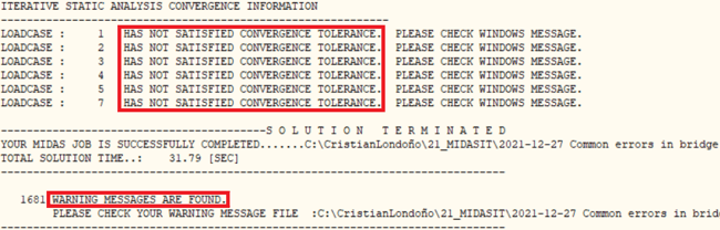
Figure 6. Warning message indicating lack of convergence in midas Civil
In those cases, the engineer should remember that the programs usually don’t solve the equilibrium equations for the Load Combinations but for the Load Cases (in the case of midas Civil). Thus, the equilibrium can be achieved only if the stabilizing and destabilizing loads are being simultaneously considered in each Load Case. In other words, the Load Combinations need to be input as Load Cases. If the equilibrium cannot yet be achieved, it would probably mean that the real structure has stability issues (most likely the destabilizing effects cannot be counteracted by the stabilizing loads).
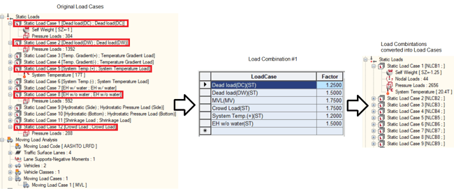
Figure 7. Load Combinations converted into Load Cases for nonlinear analysis in midas Civil
- Lack of convergence when using finite elements with releases of degrees of freedom
It is always tricky to use elements with released degrees of freedom, either explicitly or implicitly. It is made explicit when, for example, a beam element has the rotational stiffness at the ends deactivated. It is implicit when instead of doing the above, a finite axial element (truss) is used.
On many occasions, the analysis does not converge because many degrees of freedom have been released so the model is not stable during the analysis. In this case, it is sufficient to make a simple analysis of the load trajectories and make sure that, for any of the finite elements or the overall model, the structure is stable.
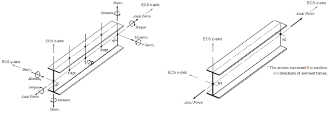
Figure 8. Two different line-elements: beam left) and truss (right)
- Lack of convergence when analyzing bridges by construction stages
If the model considers the modulus of elasticity of the concrete that is variable over time, it must be guaranteed that all parts of the structure are activated with a modulus of elasticity higher than zero. Otherwise, this will result in null stiffness, and therefore convergence problems. This can be easily detected by observing the deformations of the structure in each construction stage or by trying to activate and deactivate the variable properties to assess. In that case, the problem is most likely solved by setting the element being activated with a concrete maturity (age) greater than zero.
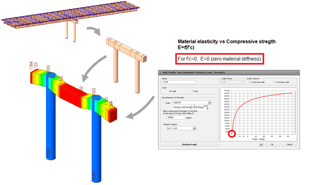
Figure 9. Excessive deformations of a cap beam when zero materials stiffness is assigned in staged construction.
Most times, the bridge engineer defines the time step sizes of the construction stage according to the main stages of the construction, for example, beam casting and placing, slab casting and placing, etc. But it is always important to ensure adequate time step sizes when time-dependent materials are used. In the following graph, the highlighted part of the curve could be wrongfully taken with the poor time step size indicated:
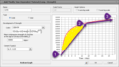 Figure 10. Poor time step for the analysis of time-dependent materials.
In midas Civil, this is not usually a problem because there are internal rules for considering smaller time steps when time-dependent materials are used.
If the convergence difficulties in a model that uses construction stages are not due to the properties of the concrete, it must be ensured that the supports of the structure are being activated at the correct times.
For the validation, many times a quick visualization of all the stages is sufficient, observing the supports that are activated. It would be easy to detect that some support is needed in the structure. It also helps to observe the error messages of the program to detect the exact construction stage where the problem occurs, as allowed by midas Civil.
- Parts of the structure are disconnected in deformed view but not in normal view
If a model shows that the structure is disconnected only when the deformation results are observed, it is most likely that the corresponding finite elements are not really connected.
On many occasions when DXF files with the base geometry of the structure have been imported, it is likely that the structure is apparently connected, but a drawing error has produced two very close but separated nodes. It is difficult to detect this in an undeformed view of the structure due to the proximity of these nodes, but it is enough to merge the nodes with tools such as Civil midas merge.
This error can also occur when the mesh of the structure has been done manually and it ignores splitting existing elements in the location of the new nodes included. In this case, simply use tools such as shrink, where you can see how the finite elements and nodes are connected thanks to the shrinkage of the edges. If the program does not shrink the elements in a specific node, it is probably necessary to intersect (intersect) the finite element in that position.
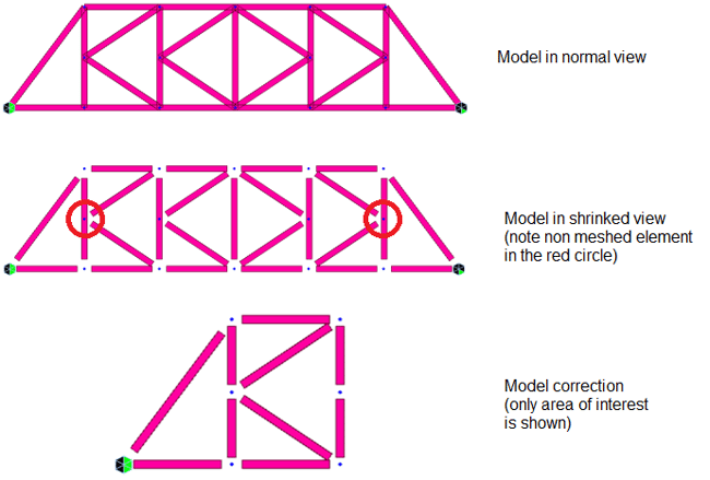
Figure 11. Usage of shrinked view function for the correction of non-connected elements.
3. Recommendations
In addition to the recommendations given above to solve these frequent errors, you can also follow some general guidelines to avoid errors or to solve them quickly:
1. Start with simple models and gradually increase the complexity as necessary
2. As much as possible, the models should be tested as new things are implemented. It is not good to wait to have the whole model implemented because the sources of errors can increase.
3. Follow the example of modeling similar cases, such as those shown in the midas Civil webinars, but always use good engineering judgment to ensure applicability in each case.
- Recent
- Popular
Subscribe S.O.S Newsletter
Похожие поиски
- » midas civil download
- » midas civil 다운
- » midas civil 2013 download
- » scaricare midas civil 7.1
- » midas civil w polsce
- » midas civil software
- » midas civil
- » midas civil 다운로드
- » midas civil ヘルプ
- » midas civil programi
ошибки midas civil
на UpdateStar
-

Более
MIDAS/Civil
MIDAS/Civil is a structural engineering software developed by MIDAS_IT. It provides a comprehensive platform for designing and analyzing various civil engineering structures such as bridges, buildings, tunnels, and more.
подробнее … -
-
Более
Dynamo for Autodesk Civil 3D 2020
Dynamo is a powerful visual programming tool designed for use with Autodesk Civil 3D 2020 software by Autodesk Inc. It allows users to create custom scripts and processes that automate design workflows, generate complex geometry, and …
подробнее … -
-
-
-
Более
Civil War in Russia
Civil War in Russia is a turn-based strategy game developed by Civil War in Russia. The game is set in Russia during the time period of 1917-1923, which saw the country divided by political and social turmoil following the Russian …
подробнее … -
-
-
Результаты поиска
ошибки midas civil
Описания содержат
ошибки midas civil
-
-
-
Более
MIDAS/Civil
MIDAS/Civil is a structural engineering software developed by MIDAS_IT. It provides a comprehensive platform for designing and analyzing various civil engineering structures such as bridges, buildings, tunnels, and more.
подробнее … -
Более
Norton Online Backup 2.10.6.9
Безопасность важных файлов, как документы или фотографии, от удаления случайного жесткого диска, вирусной атаки или любой другой ошибки, которая может привести к потере информации, хранящейся на наших жестких дисках.
подробнее … -
-
-
Более
Dynamo for Autodesk Civil 3D 2020
Dynamo is a powerful visual programming tool designed for use with Autodesk Civil 3D 2020 software by Autodesk Inc. It allows users to create custom scripts and processes that automate design workflows, generate complex geometry, and …
подробнее … -
Более
Riot Vanguard 1.12.0.177
Riot Vanguard является обязательным для запуска доблесть должным образом на вашем компьютере. Теперь, чтобы исправить эту проблему, все, что вам нужно сделать, это перезапустить. Да! Вы читаете это право.
подробнее … -
Более
COVADIS
COVADIS is a software developed by Géomédia S.A. for civil engineering professionals. It is designed to help engineers and surveyors in the design and control of high precision surveying projects.
подробнее … -
Более
WinZip Driver Updater 5.34.4.2
Обновления драйверов WinZip управляет обновления драйверов устройств, так что вам не придется! Избежать проблемы компонент оборудования и обновления вашей системы с этой простой в использовании инструмент, который будет …
подробнее …
Дополнительные заголовки, содержащие
ошибки midas civil
-
Более
MIDAS/Civil
MIDAS/Civil is a structural engineering software developed by MIDAS_IT. It provides a comprehensive platform for designing and analyzing various civil engineering structures such as bridges, buildings, tunnels, and more.
подробнее … -
-
-
Более
Dynamo for Autodesk Civil 3D 2020
Dynamo is a powerful visual programming tool designed for use with Autodesk Civil 3D 2020 software by Autodesk Inc. It allows users to create custom scripts and processes that automate design workflows, generate complex geometry, and …
подробнее … -
INTELLIGENT WORK FORUMS
FOR ENGINEERING PROFESSIONALS
Contact US
Thanks. We have received your request and will respond promptly.
Log In
Come Join Us!
Are you an
Engineering professional?
Join Eng-Tips Forums!
- Talk With Other Members
- Be Notified Of Responses
To Your Posts - Keyword Search
- One-Click Access To Your
Favorite Forums - Automated Signatures
On Your Posts - Best Of All, It’s Free!
*Eng-Tips’s functionality depends on members receiving e-mail. By joining you are opting in to receive e-mail.
Posting Guidelines
Promoting, selling, recruiting, coursework and thesis posting is forbidden.
Students Click Here
Midas Civil RecommendationsMidas Civil Recommendations(OP) 10 Feb 21 19:49 Hi, I have been trying to load rate the continuous riveted haunch plate girder with rolled steel floor beams and stringers in Midas Civil. This bridge also has varying depth of girder, the picture of which is attached with this. I haven’t used Midas so much. I am only experienced with simple steel beam bridge and prestressed concrete bridge. I am wondering if Midas Civil Expert from this forum can help me with the modeling of this bridge. Is it possible to model this kind of bridge with stringer, floor beam and varying girder depth using Wizard? If yes how? I would really appreciate your help. This load rating project is really important and I am working really hard to get this project done. Your small suggestions would be highly appreciated! Thanks!
Red Flag SubmittedThank you for helping keep Eng-Tips Forums free from inappropriate posts. |
Resources
Learn methods and guidelines for using stereolithography (SLA) 3D printed molds in the injection molding process to lower costs and lead time. Discover how this hybrid manufacturing process enables on-demand mold fabrication to quickly produce small batches of thermoplastic parts. Download Now
Examine how the principles of DfAM upend many of the long-standing rules around manufacturability — allowing engineers and designers to place a part’s function at the center of their design considerations. Download Now
Metal 3D printing has rapidly emerged as a key technology in modern design and manufacturing, so it’s critical educational institutions include it in their curricula to avoid leaving students at a disadvantage as they enter the workforce. Download Now
This ebook covers tips for creating and managing workflows, security best practices and protection of intellectual property, Cloud vs. on-premise software solutions, CAD file management, compliance, and more. Download Now |


Join Eng-Tips® Today!
Join your peers on the Internet’s largest technical engineering professional community.
It’s easy to join and it’s free.
Here’s Why Members Love Eng-Tips Forums:
 Talk To Other Members
- Notification Of Responses To Questions
- Favorite Forums One Click Access
- Keyword Search Of All Posts, And More…
 Talk To Other Members
Register now while it’s still free!
Already a member? Close this window and log in.
Join Us Close