
На чтение 5 мин Просмотров 5к.
Рассмотрим подробнее
- Техническое описание и расшифровка ошибки P0628
- Симптомы неисправности
- Причины возникновения ошибки
- Как устранить или сбросить код неисправности P0628
- Диагностика и решение проблем
- На каких автомобилях чаще встречается данная проблема
- Видео
Код ошибки P0628 звучит как «низкий уровень сигнала в цепи управления «A» топливным насосом». Часто, в программах, работающих со сканером OBD-2, название может иметь английское написание «Fuel Pump (FP) «A» Control Circuit Low».
Техническое описание и расшифровка ошибки P0628
Код OBD-2 P0628 чаще всего определяется как «в цепи управления «A» топливным насосом обнаружен низкий уровень сигнала». В большинстве случаев, код устанавливается сразу после возникновения неисправности и загорается сигнальная лампа. Но иногда код устанавливается только после того, как неисправность присутствует в течение нескольких секунд.

На старых бензиновых двигателях топливная система спроектирована таким образом, что топливо поступает в форсунки с постоянной скоростью и давлением. В этих системах питание подается на топливный насос через реле, которое подает напряжение, близкое к напряжению аккумуляторной батареи.
На современных автомобилях используются безвозвратные системы, которые не возвращают излишки топлива в бак. Вместо этого объем и давление топлива, подаваемого в форсунки, регулируются путем изменения скорости топливного насоса, что достигается за счет падения напряжения в цепи управления.
Однако обратной стороной этих систем является значительно увеличенная сложность управления топливным насосом. Которая включает в себя модули управления и различные датчики. Такие как положение педали акселератора, положения дроссельной заслонки. Входные данные от датчиков MAP / MAF, охлаждающей жидкости, температуры всасываемого воздуха, давления топлива и несколько других. Которые связаны между собой через систему шин CAN (Controller Area Network).
PCM использует все эти входные данные для расчета соответствующего давления топлива. Чтобы добиться правильного баланса, PCM регулирует скорость топливного насоса несколько раз в секунду, изменяя входное напряжение. Существуют различные способы сделать это, но наиболее распространенный метод, это изменение сопротивления для увеличения или уменьшения напряжения.
Поскольку в безвозвратных системах используется переменное напряжение для управления скоростью насоса. Поэтому труднее определить, в какой точке рабочего диапазона насоса произошел сбой. Тем не менее, в обеих конструкциях, PCM установит код P0628 и включит сигнальную лампу, при обнаружении низкого уровня сигнала в цепи управления топливным насосом.
Симптомы неисправности
Основным симптомом появления ошибки P0628 для водителя является подсветка MIL (индикатор неисправности). Также его называют Check engine или просто «горит чек».
Также они могут проявляться как:
- Загорится контрольная лампа «Check engine» на панели управления (код будет записан в память как неисправность).
- Также могут присутствовать другие связанные коды неисправностей.
- Двигатель может не запускаться или запускаться, а затем глохнуть.
- Плавающие обороты, а также попытки заглохнуть на холостом ходу.
- Недостаточная подача топлива из-за ненадлежащей работы топливного насоса.
- Снижение мощности двигателя.
- Повышенный расход топлива.
- Двигатель глохнет при достижении рабочей температуры.
- Симптомы могут отсутствовать, кроме сохраненного кода неисправности.
Неисправность цепи топливного насоса может привести к возникновению проблем с запуском двигателя, поэтому ошибка P0628 считается серьезной. Если ее игнорировать, топливный насос может полностью выйти из строя.
Причины возникновения ошибки
Код P0628 может означать, что произошла одна или несколько следующих проблем:
- Проблемы с самим топливным насосом.
- Реле топливного насоса неисправно, напряжение на топливный насос не поступает.
- Повреждение жгута проводов приводит к обрыву цепи питания топливного насоса.
- Ослабленные или поврежденные разъемы.
- Цепь обратной связи имеет обрыв.
- При небольшом ударе мог сработать инерционный выключатель, который размыкает цепь топливного насоса.
- Перегорел предохранитель топливного насоса из-за короткого замыкания на массу.
- Неисправная шина CAN.
- Неисправен модуль управления двигателем (PCM).
Как устранить или сбросить код неисправности P0628
Некоторые предлагаемые шаги для устранения неполадок и исправления кода ошибки P0628:
- Считайте все сохраненные данные и коды ошибок с помощью сканера OBD-II. Чтобы выяснить, когда и при каких обстоятельствах появилась ошибка P0628.
- Очистите коды ошибок с памяти компьютера и проведите тест-драйв автомобиля, чтобы выяснить, появляется ли неисправность снова.
- Проверьте работоспособность топливного насоса.
- Протестируйте реле топливного насоса.
- Визуально осмотрите электрические провода и соединения, на предмет ослабления и наличия повреждений.
- Проверьте инерционный выключатель, если необходимо, включите его.
- При необходимости замените предохранитель.
- Снова очистите код ошибки с памяти компьютера, проведите тест-драйв автомобиля, чтобы выяснить, решена ли проблема.
Диагностика и решение проблем
Для диагностики цепей топливного насоса и устранения кода неисправности P0628 необходимо наличие электрической схемы, для вашего автомобиля. После этого можно приступать к дальнейшим действиям.
Если автомобиль запускается и движется, нареканий на управляемость нет, скорее всего есть обрыв в цепи обратной связи между PCM и цепью напряжения питания топливного насоса. При необходимости отремонтируйте.
Когда автомобиль не заводится или заводится и глохнет из-за низкого давления топлива, проверьте предохранитель топливного насоса. Если он перегорел, проверьте цепь питания топливного насоса на замыкание на массу.
Снимите реле топливного насоса (FP), а затем проверьте сопротивление между цепью напряжения на разъеме топливного насоса и массой. При небольшом сопротивлении, указывающим на замыкание на массу, отключите топливный насос и проверьте его снова.
Если после отсоединения топливного насоса он показывает высокое или бесконечное сопротивление, замените закороченный топливный насос. При низком сопротивлении после отключения топливного насоса, устраните короткое замыкание в цепи питания FP.
После проверки электрических цепей, скорее всего будет несколько сценариев. Либо ошибка P0628 пропадет, так как была устранена проблема с проводкой. Либо проблема в неисправном реле или топливном насосе.
На каких автомобилях чаще встречается данная проблема
Проблема с кодом P0628 может встречаться на различных машинах, но всегда есть статистика, на каких марках эта ошибка присутствует чаще. Вот список некоторых из них:
- Audi
- Chevrolet (Шевроле Каптива, Спарк)
- Chrysler
- Daewoo (Дэу Матиз)
- Dodge (Додж Рам)
- Ford (Форд Транзит, Фокус)
- Jeep
- Mazda
- Mercedes
- Mitsubishi (Митсубиси Паджеро, L200)
- Nissan (Ниссан Навара, Патфайндер)
- Opel (Опель Антара, Корса)
- Toyota
- ВАЗ 2107, 2114
- Газель
- Лада Гранта, Приора
- Уаз
С кодом неисправности Р0628 иногда можно встретить и другие ошибки. Наиболее часто встречаются следующие: P0627, P0629, P062A, P1260.
Видео

Содержание
- Что означает код P0628?
- Каковы общие причины кода P0628?
- Каковы симптомы кода P0628?
- Как вы устраняете неисправность кода P0628?
- Шаг 1
- Шаг 2
- Шаг 3
- Шаг 4
- Шаг 5
- Коды, связанные с P0628
| Код неисправности | Расположение ошибки | Вероятная причина |
|---|---|---|
| p0628 | Управление топливным насосом — цепь низкая | Проводка короткая к земле, реле, топливный насос |
СПЕЦИАЛЬНЫЕ ЗАМЕЧАНИЯ: Код OBD II P0628 является одним из самых неоднозначных кодов в том смысле, что он имеет много возможных определений, некоторые из которых относятся к бензиновым, а другие — к дизельным., Также обратите внимание, что в этом руководстве будет обсуждаться код P0628 с определением «Цепь управления топливным насосом« A »- низкий уровень», поскольку это определение относится к большинству применений бензина.
Хотя все определения P0628 так или иначе применяются к низким напряжениям цепи управления топливным насосом, процедуры тестирования для этого кода сильно различаются в зависимости от применения дизельного топлива и бензина. Это особенно верно, когда код P0628 присутствует в бензиновом применении, в котором используется безвозвратная топливная система, в отличие от системы постоянного давления, которая сбрасывает давление топлива с помощью регулятора давления.
В дизельных двигателях этот код относится к низкому напряжению цепи управления топливоподкачивающего насоса. В дизельных системах подъемный насос размещается внутри топливного бака или иногда ближе к главному топливному насосу, чтобы обеспечить постоянную подачу топлива низкого давления в главный топливный насос.
Некоторые (общие) возможные определения P0628 могут включать следующее:
Тем не менее, обратите внимание, что возможны и другие определения, в зависимости от марки и модели соответствующего приложения, а также года производства соответствующего приложения. Поэтому, ДОЛЖНА быть сделана каждая попытка подтвердить определение P0628. как это относится к приложение работает для предотвращения путаницы, неправильной диагностики и ненужной замены дорогих деталей и компонентов.
Из вышесказанного должно быть очевидно, что данное руководство не может предоставить подробную диагностическую / ремонтную информацию, которая будет действительна для всех приложений при всех возможных условиях, что означает, что общая информация, представленная здесь, предназначена только для общих информационных целей, и поэтому она должна НЕ использовать в любой диагностической процедуре для кода P0628 без надлежащей ссылки на приложение, над которым выполняется работа. КОНЕЦ СПЕЦИАЛЬНЫХ ЗАМЕЧАНИЙ.
Код OBD II P0628 — это общий код, который чаще всего определяется как «Цепь управления« Топливный насос «А» — Низкий »(это определение относится к большинству применений с бензином) и устанавливается, когда PCM обнаруживает аномально низкое напряжение в топливном насосе. схема управления. В большинстве приложений устанавливается код P0628, и сигнальная лампа загорается сразу после возникновения неисправности, хотя в некоторых случаях код устанавливается только после того, как неисправность присутствует в течение нескольких секунд.
В старых бензиновых системах топливная система спроектирована таким образом, что топливо подается в инжекторы с постоянной скоростью и давлением. В этих системах питание подается на топливный насос через реле, которое подает напряжение, близкое к напряжению аккумулятора, к насосу, который всегда работает с постоянной скоростью, обеспечивая тем самым подачу топлива с объемом и скоростью, обеспечивающими постоянное питание двигателя. адекватная подача топлива, независимо от условий эксплуатации в любой данный момент.
Для контроля как объема, так и давления топлива на уровнях, которые не вызывают перерасход топлива, топливная рампа оснащена пружинным регулятором давления, который открывается под давлением топлива, подаваемым насосом, когда потребность в топливе падает, например, когда дроссель закрыт. Таким образом, инжекторы всегда снабжаются достаточным количеством топлива под давлением, указанным для применения, но избыточное давление отводится обратно в бак через регулятор давления, когда потребность в топливе падает. Система этого типа также оснащена датчиком давления топлива, который контролирует систему как для ненормально низкого, так и высокого давления.
С другой стороны, современные приложения все чаще используют «безвозвратные» системы, которые не возвращают избыточное топливо в бак. Вместо этого объем и давление топлива, подаваемого в инжекторы, контролируются путем изменения скорости топливного насоса, что достигается путем снижения напряжения в цепи управления. Одним из главных преимуществ этих конструкций топливной системы является то, что, поскольку топливо не перемешивается или не нагревается так же, как в более старых системах, объем паров топлива значительно уменьшается, что является большим с точки зрения выбросов.
Однако недостатком этих систем является значительно возросшая сложность системы управления топливным насосом, которая включает в себя модули управления и датчики, которые не включены в системы управления системами постоянного давления. Например, типичная безвозвратная система включает в себя один или оба датчика положения педали акселератора, датчик (и) положения дроссельной заслонки, входные сигналы от датчиков MAP / MAF (абсолютный массовый расход / давление в коллекторе), данные от датчиков охлаждающей жидкости двигателя и температуры всасываемого воздуха, датчик давления топлива и несколько других, которые все связаны через систему шины CAN (Controller Area Network).
PCM использует все эти входные данные для расчета подходящего давления топлива, которое, с одной стороны, гарантирует, что двигатель не испытывает недостатка топлива, а также для того, чтобы форсунки впрыскивали правильный объем топлива в цилиндры с другой, что может превысить желаемый объем, если давление топлива слишком высокое в любой данный момент. Чтобы получить этот баланс правильно, PCM регулирует скорость топливного насоса несколько раз в секунду, изменяя входное напряжение топливных насосов. Существуют различные способы достижения этого, но наиболее распространенный способ заключается в изменении сопротивления источника питания топливных насосов для увеличения или уменьшения напряжения, которое в конечном итоге достигает двигателя насоса.
Таким образом, из вышесказанного должно быть ясно, что проверка неисправности или состояния низкого напряжения в источнике питания системы постоянного давления включает в себя не что иное, как измерение сопротивления и целостности проводки топливных насосов. Однако, поскольку в системах безвозвратно используются переменное напряжение / сопротивление для управления скоростью насоса, определить, в какой точке рабочего диапазона насоса установлен код низкого напряжения P0628, не так просто, и загорелась сигнальная лампа. Тем не менее, в обеих конструкциях PCM установит код P0628 и включит сигнальную лампу, когда в цепи управления топливных насосов будет обнаружено низкое напряжение.
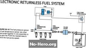
На рисунке ниже показана упрощенная схема типичной системы безвозвратного впрыска топлива. Обратите внимание на отсутствие регулятора давления топлива, который выполняет функцию отвода избыточного давления обратно в топливный бак в системах постоянного давления.
Каковы общие причины кода P0628?
Общие причины P0628 могут включать следующее:
Неисправный или неисправный PCM или модуль управления топливом, который может включать или не включать модуль управления скоростью топливного насоса. Однако обратите внимание, что это редкие события, и неисправность следует искать в другом месте, прежде чем заменять какой-либо контроллер.
Каковы симптомы кода P0628?
Помимо сохраненного кода неисправности и световой сигнальной лампы, некоторые другие распространенные симптомы P0628 могут включать следующие:
НОТА: Обратите внимание, что большинство, если не все, перечисленные здесь симптомы также применимы к дизельным двигателям с кодом P0268.
Как вы устраняете неисправность кода P0628?
СПЕЦИАЛЬНЫЕ ЗАМЕЧАНИЯ ПО ДИЗЕЛЬНЫМ ПОДЪЕМНЫМ НАСОСАМ. Несмотря на то, что дизельные подъемные насосы выполняют другие функции, чем топливные насосы на бензиновых двигателях, процедуры диагностики / ремонта для кода P0628 для дизельных двигателей аналогичны процедурам для кода P0628 для бензиновых двигателей. В обоих случаях для правильной работы насоса требуется определенное напряжение, и помимо того факта, что дизельные подъемные насосы производят намного более низкие давления, чем бензиновые топливные насосы, более низкое, чем ожидалось, входное напряжение может привести к тому, что насос не будет выдавать правильный объем топлива при указанном давлении, что, в свою очередь, может привести к тому, что главный топливный насос не будет работать из-за постоянной подачи топлива. Таким образом, следуя шагам диагностики / ремонта, описанным в этом руководстве, можно разрешить код P0628 для дизельных применений девять раз из каждых десяти. КОНЕЦ СПЕЦИАЛЬНЫХ ЗАМЕЧАНИЙ.
Шаг 1
Запишите все имеющиеся коды неисправностей, а также все доступные данные стоп-кадра. Эта информация может быть полезна, если впоследствии будет диагностирована прерывистая неисправность.
ПРИМЕЧАНИЕ № 1: Код P0628 очень часто сопровождается кодами низкого давления топлива. Однако не поддавайтесь искушению исследовать причины условий низкого давления топлива, отличных от состояния низкого напряжения в цепи управления топливными насосами, поскольку эти коды почти всегда являются результатом P0628, а не причиной состояния низкого давления топлива. Обратите внимание, что это верно для дизельных систем, в которых также используются топливоподъемные насосы.
ЗАМЕТКА 2: Если присутствуют коды, относящиеся к низким системным напряжениям, существует более чем вероятность того, что низкое системное напряжение является основной причиной P0628, что означает, что, если такие коды присутствуют, они ДОЛЖНЫ быть устранены до делается любая попытка диагностики P0628 или кодов, связанных с низким давлением топлива.
Шаг 2
Обратитесь к руководству по применению, чтобы определить, имеет ли топливная система постоянное давление или безвозвратный вариант, поскольку процедура диагностики для последнего типа системы немного сложнее, чем для первого типа.
Независимо от типа системы, подавляющее большинство сбоев происходит в проводке между реле топливного насоса и самим топливным насосом. Имея это в виду, обратитесь к руководству, чтобы определить все соответствующие компоненты, проводку и разъемы, а также цветовое кодирование и функции каждого провода в цепи управления.
Шаг 3
Как только все провода и компоненты будут идентифицированы, выполните тщательный визуальный осмотр всей проводки; ищите поврежденную, сгоревшую, закороченную, разъединенную и корродированную проводку и / или разъемы. При необходимости выполните ремонт, очистите все коды и выполните повторное сканирование системы, чтобы убедиться, что код возвращается.
Шаг 4
Если код сохраняется, но видимого повреждения в соответствующей проводке не обнаружено, подготовьтесь к выполнению проверок сопротивления, целостности и заземления на всей связанной проводке. В системах с постоянным давлением это относительно просто, поскольку схема очень проста. Тем не менее, обратите особое внимание на непрерывность всех разъемов и убедитесь, что катушка реле насоса показывает указанное сопротивление.
В системе такого типа схема управления должна нести напряжение батареи или очень близко к нему, поэтому обязательно проверяйте, что батарея полностью заряжена при выполнении этой проверки. Кроме того, убедитесь, что заземление системы хорошее, проверив положительный заряд аккумулятора и подходящие точки заземления как на кузове, так и на двигателе. При необходимости выполните ремонт, чтобы убедиться, что заземление системы восстановлено.
Обязательно проверяйте наличие короткого замыкания между положительной и отрицательной сторонами цепи управления. Все производители имеют максимально допустимые пределы для напряжения в цепи заземления, и, хотя идеальным является отсутствие напряжения в этой цепи, иногда случается, что некоторое напряжение присутствует из-за множества причин и факторов. Если обнаружено чрезмерное напряжение, иногда предпочтительнее заменить всю соответствующую проводку, чем проводить часы в поисках предельного короткого замыкания между массой и напряжением батареи.
Тем не менее, сравните все полученные показания со значениями, указанными в руководстве, и при необходимости выполните ремонт, чтобы убедиться, что все электрические значения находятся в пределах, указанных производителем. Очистите все коды после завершения ремонта и повторите сканирование системы, чтобы увидеть, вернется ли код.
НОТА: Если код сохраняется в системе постоянного давления, убедитесь, что реле топливного насоса полностью исправно, поскольку точки контакта внутри электромеханических реле могут иногда препятствовать протеканию тока, если точки повреждены из-за длительного использования или искрения. Замените реле топливного насоса, если есть сомнения в его состоянии или исправности.
Шаг 5
Этапы диагностики / ремонта вплоть до этапа 5 почти наверняка разрешат P0628 как для бензиновых топливных систем с постоянным давлением, так и для систем дизельных подъемных насосов.
Однако, если неисправность не устраняется после шага 5 в безвозвратной системе, возникает необходимость проверить все цепи и компоненты всей системы управления топливного насоса, поскольку вся система участвует в расчете и подаче напряжения питания, которое в конечном итоге отправляется на топливный насос в любой момент. Как правило, эти тесты включают проверки работоспособности всех замешанные датчиков и модулей управления, а также сопротивление, опорное напряжение, непрерывность и подключение заземления во все связанную проводке и цепях.
Имейте в виду, однако, что эта процедура может быть чрезвычайно сложной даже для профессиональных техников, и поэтому ее НЕ ДОЛЖНЫ предпринимать непрофессионалы, которым не нравится идея диагностики неисправностей в системе CAN или которые не имеют доступа к подходящей диагностике. оборудование, все соответствующие справочные данные и / или необходимые диагностические навыки.
Другие типовые испытания включают проверку как напряжения цепи управления топливного насоса, так и фактического давления топлива в установленных отверстиях дроссельной заслонки. Хотя это можно сделать с некоторыми сканерами, которые имеют функции управления, эта процедура НЕ рекомендуется, если отсутствует подходящее оборудование и справочные данные. Фактически, если шаги с 1 по 4 не помогли решить проблему, более разумным вариантом является направление автомобиля дилеру или другой компетентной ремонтной мастерской для профессиональной диагностики и ремонта.
Коды, связанные с P0628
Some NEW HOLLAND Tractor Fault Codes DTC.
Type of error / Code of error / Description of Error
ENG — 111 — engine controller failure — hardware failure
ENG — 115 — engine speed sensor (8.3, 9 liter) or cam sensor (15 liter) is failed
ENG — 121 — engine position sensor (8.3, 9 liter) or crankshaft sensor (15 liter) is failed
ENG — 122 — boost pressure sensor voltage is too high
ENG — 123 — boost pressure sensor voltage is too low
ENG — 124 — boost pressure level has exceeded the warning limit.
ENG — 131 — decelerator or hand throttle (STD cab) position potentiometer voltage is too high
ENG — 132 — decelerator or hand throttle (STD cab) position potentiometer voltage is too low
ENG — 133 — decelerator (STD cab) position potentiometer voltage is too high
ENG — 134 — decelerator (STD cab) position potentiometer voltage is too low
ENG — 135 — oil pressure sensor voltage is too high
ENG — 141 — oil pressure sensor voltage is too low
ENG — 143 — oil pressure level has fallen below the warning limit.
ENG — 144 — coolant temperature sensor voltage is too high
ENG — 145 — coolant temperature sensor voltage is too low
ENG — 146 — coolant temperature level has exceeded the warning limit.
ENG — 147 — frequency throttle signal shorted high
ENG — 148 — frequency throttle signal shorted low
ENG — 151 — coolant temperature level has exceeded the warning limit.
ENG — 153 — intake manifold temperature sensor voltage is too high
ENG — 154 — intake manifold temperature sensor voltage is too low
ENG — 155 — intake manifold temperature level has exceeded the warning limit.
ENG — 187 — sensor supply 2 voltage is too low.
ENG — 191 — A/C clutch driver shorted to ground when ON.
ENG — 211 — communications problem with armrest, instrumentation, or transmission controllers
ENG — 212 — oil temperature sensor voltage is too high
ENG — 213 — oil temperature sensor voltage is too low
ENG — 214 — oil temperature sensor voltage is above normal range
ENG — 219 — oil level — remote reservoir is too low. Add oil.
ENG — 221 — ambient air pressure sensor voltage is too high
ENG — 222 — ambient air pressure sensor voltage is too low
ENG — 223 — CORS — burn valve solenoid is shorted either low or high
ENG — 227 — sensor supply 2 voltage is too high.
ENG — 234 — engine speed has exceed the overspeed warning limit.
ENG — 235 — engine coolant level is low. Add coolant fluid.
ENG — 237 — external speed multi unit sync command input data incorrect.
ENG — 241 — vehicle speed signal lost
ENG — 242 — vehicle speed signal intermittent / tampering
ENG — 243 — error detected in exhaust brake relay
ENG — 245 — fan clutch voltage too low
ENG — 254 — fuel shutoff valve voltage too low
ENG — 255 — fuel shutoff valve voltage too high
ENG — 259 — fuel shutoff valve mechanically stuck open.
ENG — 263 — fuel temperature sensor voltage is too high
ENG — 265 — fuel temperature sensor voltage is too low
ENG — 268 — fuel pressure in pump is not changing with operating conditions.
ENG — 271 — front pumping control valve current is low
ENG — 272 — front pumping control valve current is high
ENG — 273 — rear pumping control valve current is low
ENG — 274 — rear pumping control valve current is high
ENG — 275 — front pumping element is failed
ENG — 276 — injection control valve current is out of range
ENG — 277 — injection control valve is failed
ENG — 278 — fuel lift pump is failed
ENG — 279 — injection control valve current is out of range
ENG — 281 — front pumping element is failed
ENG — 282 — rear pumping element is failed
ENG — 283 — engine speed / position sensor supply voltage is too high
ENG — 284 — engine speed / position sensor supply voltage is too low
ENG — 285 — J1939 parameter was set to be multiplexed, but not received (timeout error)
ENG — 286 — J1939 parameter was set to be multiplexed, but not available from all sources (config error)
ENG — 287 — multiplexing throttle parameter and a data error was received — data invalid
ENG — 288 — multiplexing remote throttle parameter and a data error was received — data invalid
ENG — 293 — hydraulic fan hydraulic oil temperature sensor voltage is too high
ENG — 294 — hydraulic fan hydraulic oil temperature sensor voltage is too low
ENG — 295 — ambient air pressure data invalid
ENG — 297 — OEM pressure sensor voltage is too high.
ENG — 298 — OEM pressure sensor voltage is too low.
ENG — 299 — engine shutdown by other than keyswitch (i.e. via data bus command)
ENG — 319 — real time clock in controller has lost power
ENG — 328 — rear pumping element is failed
ENG — 329 — CAPS pump has an overpumping failure
ENG — 338 — idle shutdown vehicle accessory relay voltage is too high
ENG — 339 — idle shutdown vehicle accessory relay voltage is too low
ENG — 341 — all data written during powerdown cycle was lost (checksum error)
ENG — 343 — engine controller failure — hardware failure
ENG — 349 — measured speed is too high.
ENG — 352 — 5 volt sensor supply voltage is too low
ENG — 378 — front fueling current is too low
ENG — 379 — front fueling current is too high
ENG — 381 — error detected in cold start relay 1
ENG — 382 — error detected in cold start relay 2
ENG — 385 — 5 volt sensor supply voltage is too high
ENG — 386 — 5 volt sensor supply voltage is too high
ENG — 387 — decelerator or hand throttle (STD cab) 5 volt supply voltage is too high
ENG — 388 — engine brake driver 1 circuit failure
ENG — 392 — engine brake driver 2 circuit failure
ENG — 393 — engine brake driver 3 circuit failure
ENG — 394 — front timing current is too low.
ENG — 395 — front timing current is too high.
ENG — 396 — rear fueling current is too low
ENG — 397 — rear fueling current is too high
ENG — 398 — rear timing current is too low
ENG — 399 — rear timing current is too high
ENG — 412 — J1708 data link cannot transmit
ENG — 414 — J1708 data link not fast enough
ENG — 415 — oil pressure level has fallen below the very low warning limit.
ENG — 418 — water in fuel sensor indicates the water in the fuel filter needs to be drained.
ENG — 419 — boost pressure data invalid
ENG — 422 — engine coolant level sensor (optional) is failed or the jumper plug is missing
ENG — 426 — J1939 data link cannot transmit
ENG — 427 — J1939 data link not fast enough
ENG — 428 — water in fuel sensor voltage is too high.
ENG — 429 — water in fuel sensor voltage is too low.
ENG — 431 — hand throttle (STD cab) idle validation switches are both closed
ENG — 432 — hand throttle (STD cab) position potentiometer and switches disagree.
ENG — 433 — boost pressure level disagrees with engine operation conditions (speed & power)
ENG — 434 — unswitched 12 volt supply voltage disconnected without normal key off sequence.
ENG — 435 — oil pressure data invalid
ENG — 441 — battery voltage is too low (less than 6 volts)
ENG — 442 — battery voltage is too high
ENG — 443 — decelerator or hand throttle (STD cab) 5 volt supply voltage is too low
ENG — 444 — low voltage detected at OEM 5 volt supply
ENG — 449 — fuel pressure level has exceeded the warning limit.
ENG — 451 — fuel pressure sensor voltage is too high
ENG — 452 — fuel pressure sensor voltage is too low
ENG — 456 — fuel pressure in pump is not changing with operating conditions.
ENG — 465 — wastegate 1 voltage is too high
ENG — 466 — wastegate 1 voltage is too low
ENG — 482 — fuel pressure sensor voltage low
ENG — 483 — rear bank post actuactor pressure voltage high
ENG — 484 — rear bank post actuactor pressure voltage low
ENG — 485 — rear fueling actuator overfueling
ENG — 486 — rear fueling actuator underfueling
ENG — 488 — intake manifold temperature level has exceeded the warning limit.
ENG — 489 — measured speed sensor data low
ENG — 491 — wastegate 2 voltage is too high
ENG — 492 — wastegate 2 voltage is too low
ENG — 493 — the injection control identifier circuit in the harness has failed.
ENG — 496 — engine speed / position sensor №2 supply is too low
![]()
NEW HOLLAND Tractor Fault Codes DTC
[ADIC] – 1 – Processor memory error (EEPROM checksum error)
[ADIC] – 11 – Fuel tank level sensor B2/1 signal faulty (short circuit to earth)
[ADIC] – 20 – Pressure sensor B3 signal faulty (line interruption or short circuit to +12 V)
[ADIC] – 250 – CAN Bus OFF
[ARU] – 1 – Processor error (register test)
[ARU] – 10 – Receipt message from AUX1 was not obtained correctly following reprogramming from 0 to 1
[ARU] – 11 – Receipt message from AUX2 was not obtained correctly following reprogramming from 0 to 2
[ARU] – 12 – Receipt message from AUX3 was not obtained correctly following reprogramming from 0 to 3
[ARU] – 13 – Receipt message from AUX4 was not obtained correctly following reprogramming from 0 to 4
[ARU] – 14 – Receipt message from AUX5 was not obtained correctly following reprogramming from 0 to 5
[ARU] – 15 – Receipt message from AUX6 was not obtained correctly following reprogramming from 0 to 6
[ARU] – 16 – Receipt message from AUX7 was not obtained correctly following reprogramming from 0 to 7
[ARU] – 17 – Receipt message from AUX8 was not obtained correctly following reprogramming from 0 to 8
[ARU] – 2 – Processor error (flash memory)
[ARU] – 20 – Supply voltage too low (< 8 V) [ARU] – 21 – Supply voltage too high (> 18 V)
[ARU] – 30 – Signal from AUX stick with catch (AUX1) below permissible range
[ARU] – 31 – Signal from AUX stick with catch (AUX1) above permissible range
[ARU] – 32 – Signal from AUX stick without catch (AUX2) below permissible range
[ARU] – 33 – Signal from AUX stick without catch (AUX2) above permissible range
[ARU] – 34 – Signal from AUX stick (AUX3) below permissible range
[ARU] – 35 – Signal from AUX stick (AUX3) above permissible range
[ARU] – 36 – Signal from hand throttle lever below permissible range
[ARU] – 37 – Signal from hand throttle lever above permissible range
[ARU] – 38 – Signal from cruise control ON/OFF button below permissible range
[ARU] – 39 – Signal from cruise control ON/OFF button above permissible range
[ARU] – 40 – Signal from + button below permissible range
[ARU] – 41 – Signal from + button above permissible range
[ARU] – 42 – Signal from finger wheel below permissible range
[ARU] – 43 – Signal from finger wheel above permissible range
[ARU] – 5 – Processor error (data memory)
[ARU] – 71 – CAN Bus OFF
[AUX1] – 11 – Missing receipt message 1 default
[AUX1] – 12 – Missing receipt message 2 configuration
[AUX1] – 13 – Implausible receipt message 1 default
[AUX1] – 14 – Implausible receipt message 2 configuration
[AUX1] – 15 – Incorrect CAN message
[AUX1] – 16 – Processor error (EEPROM inconsistent)
[AUX1] – 17 – A neutral command is awaited following a CAN error
[AUX1] – 21 – Supply voltage too low (< 8.2 V) [AUX1] – 22 – Supply voltage too high (> 18 V)
[AUX1] – 23 – Spool deflection too small
[AUX1] – 24 – Spool deflection too great
[AUX1] – 25 – Float not achieved
[AUX1] – 26 – Spool position amended manually
[AUX1] – 31 – Supply voltage too low (< 8 V), valve switches off output [AUX1] – 32 – Supply voltage too high (> 36 V), valve switches off output
[AUX1] – 41 – Supply voltage far too high (> 45 V)
[AUX1] – 42 – Output error (output for pilot solenoid valve)
[AUX1] – 43 – Route recording error
[AUX1] – 81 – Spool valve will not return to neutral position
[AUX1] – 82 – Valve spool not in neutral position when switched on
[AUX1] – 83 – Checksum error
[AUX2] – 11 – Missing receipt message 1 default
[AUX2] – 12 – Missing receipt message 2 configuration
[AUX2] – 13 – Implausible receipt message 1 default
[AUX2] – 14 – Implausible receipt message 2 configuration
[AUX2] – 15 – Incorrect CAN message
[AUX2] – 16 – Processor error (EEPROM inconsistent)
[AUX2] – 17 – A neutral command is awaited following a CAN error
[AUX2] – 21 – Supply voltage too low (< 8.2 V) [AUX2] – 22 – Supply voltage too high (> 18 V)
[AUX2] – 23 – Spool deflection too small
[AUX2] – 24 – Spool deflection too great
[AUX2] – 25 – Float not achieved
[AUX2] – 26 – Spool position amended manually
[AUX2] – 31 – Supply voltage too low (< 8 V), valve switches off output [AUX2] – 32 – Supply voltage too high (> 36 V), valve switches off output
[AUX2] – 41 – Supply voltage far too high (> 45 V)
[AUX2] – 42 – Output error (output for pilot solenoid valve)
[AUX2] – 43 – Route recording error
[AUX2] – 81 – Spool valve will not return to neutral position
[AUX2] – 82 – Valve spool not in neutral position when switched on
[AUX2] – 83 – Checksum error
[AUX3] – 11 – Missing receipt message 1 default
[AUX3] – 12 – Missing receipt message 2 configuration
[AUX3] – 13 – Implausible receipt message 1 default
[AUX3] – 14 – Implausible receipt message 2 configuration
[AUX3] – 15 – Incorrect CAN message
[AUX3] – 16 – Processor error (EEPROM inconsistent)
[AUX3] – 17 – A neutral command is awaited following a CAN error
[AUX3] – 21 – Supply voltage too low (< 8.2 V) [AUX3] – 22 – Supply voltage too high (> 18 V)
[AUX3] – 23 – Spool deflection too small
[AUX3] – 24 – Spool deflection too great
[AUX3] – 25 – Float not achieved
[AUX3] – 26 – Spool position amended manually
[AUX3] – 31 – Supply voltage too low (< 8 V), valve switches off output [AUX3] – 32 – Supply voltage too high (> 36 V), valve switches off output
[AUX3] – 41 – Supply voltage far too high (> 45 V)
[AUX3] – 42 – Output error (output for pilot solenoid valve)
[AUX3] – 43 – Route recording error
[AUX3] – 81 – Spool valve will not return to neutral position
[AUX3] – 82 – Valve spool not in neutral position when switched on
[AUX3] – 83 – Checksum error
[AUX4] – 11 – Missing receipt message 1 default
[AUX4] – 12 – Missing receipt message 2 configuration
[AUX4] – 13 – Implausible receipt message 1 default
[AUX4] – 14 – Implausible receipt message 2 configuration
[AUX4] – 15 – Incorrect CAN message
[AUX4] – 16 – Processor error (EEPROM inconsistent)
[AUX4] – 17 – A neutral command is awaited following a CAN error
[AUX4] – 21 – Supply voltage too low (< 8.2 V) [AUX4] – 22 – Supply voltage too high (> 18 V)
[AUX4] – 23 – Spool deflection too small
[AUX4] – 24 – Spool deflection too great
[AUX4] – 25 – Float not achieved
[AUX4] – 26 – Spool position amended manually
[AUX4] – 31 – Supply voltage too low (< 8 V), valve switches off output [AUX4] – 32 – Supply voltage too high (> 36 V), valve switches off output
[AUX4] – 41 – Supply voltage far too high (> 45 V)
[AUX4] – 42 – Output error (output for pilot solenoid valve)
[AUX4] – 43 – Route recording error
[AUX4] – 81 – Spool valve will not return to neutral position
[AUX4] – 82 – Valve spool not in neutral position when switched on
[AUX4] – 83 – Checksum error
[AUX5] – 11 – Missing receipt message 1 default
[AUX5] – 12 – Missing receipt message 2 configuration
[AUX5] – 13 – Implausible receipt message 1 default
[AUX5] – 14 – Implausible receipt message 2 configuration
[AUX5] – 15 – Incorrect CAN message
[AUX5] – 16 – Processor error (EEPROM inconsistent)
[AUX5] – 17 – A neutral command is awaited following a CAN error
[AUX5] – 21 – Supply voltage too low (< 8.2 V) [AUX5] – 22 – Supply voltage too high (> 18 V)
[AUX5] – 23 – Spool deflection too small
[AUX5] – 24 – Spool deflection too great
[AUX5] – 25 – Float not achieved
[AUX5] – 26 – Spool position amended manually
[AUX5] – 31 – Supply voltage too low (< 8 V), valve switches off output [AUX5] – 32 – Supply voltage too high (> 36 V), valve switches off output
[AUX5] – 41 – Supply voltage far too high (> 45 V)
[AUX5] – 42 – Output error (output for pilot solenoid valve)
[AUX5] – 43 – Route recording error
[AUX5] – 81 – Spool valve will not return to neutral position
[AUX5] – 82 – Valve spool not in neutral position when switched on
[AUX5] – 83 – Checksum error
[AUX6] – 11 – Missing receipt message 1 default
[AUX6] – 12 – Missing receipt message 2 configuration
[AUX6] – 13 – Implausible receipt message 1 default
[AUX6] – 14 – Implausible receipt message 2 configuration
[AUX6] – 15 – Incorrect CAN message
[AUX6] – 16 – Processor error (EEPROM inconsistent)
[AUX6] – 17 – A neutral command is awaited following a CAN error
[AUX6] – 21 – Supply voltage too low (< 8.2 V) [AUX6] – 22 – Supply voltage too high (> 18 V)
[AUX6] – 23 – Spool deflection too small
[AUX6] – 24 – Spool deflection too great
[AUX6] – 25 – Float not achieved
[AUX6] – 26 – Spool position amended manually
[AUX6] – 31 – Supply voltage too low (< 8 V), valve switches off output [AUX6] – 32 – Supply voltage too high (> 36 V), valve switches off output
[AUX6] – 41 – Supply voltage far too high (> 45 V)
[AUX6] – 42 – Output error (output for pilot solenoid valve)
[AUX6] – 43 – Route recording error
[AUX6] – 81 – Spool valve will not return to neutral position
[AUX6] – 82 – Valve spool not in neutral position when switched on
[AUX6] – 83 – Checksum error
[AUX7] – 11 – Missing receipt message 1 default
[AUX7] – 12 – Missing receipt message 2 configuration
[AUX7] – 13 – Implausible receipt message 1 default
[AUX7] – 14 – Implausible receipt message 2 configuration
[AUX7] – 15 – Incorrect CAN message
[AUX7] – 16 – Processor error (EEPROM inconsistent)
[AUX7] – 17 – A neutral command is awaited following a CAN error
[AUX7] – 21 – Supply voltage too low (< 8.2 V) [AUX7] – 22 – Supply voltage too high (> 18 V)
[AUX7] – 23 – Spool deflection too small
[AUX7] – 24 – Spool deflection too great
[AUX7] – 25 – Float not achieved
[AUX7] – 26 – Spool position amended manually
[AUX7] – 31 – Supply voltage too low (< 8 V), valve switches off output [AUX7] – 32 – Supply voltage too high (> 36 V), valve switches off output
[AUX7] – 41 – Supply voltage far too high (> 45 V)
[AUX7] – 42 – Output error (output for pilot solenoid valve)
[AUX7] – 43 – Route recording error
[AUX7] – 81 – Spool valve will not return to neutral position
[AUX7] – 82 – Valve spool not in neutral position when switched on
[AUX7] – 83 – Checksum error
[AUX8] – 11 – Missing receipt message 1 default
[AUX8] – 12 – Missing receipt message 2 configuration
[AUX8] – 13 – Implausible receipt message 1 default
[AUX8] – 14 – Implausible receipt message 2 configuration
[AUX8] – 15 – Incorrect CAN message
[AUX8] – 16 – Processor error (EEPROM inconsistent)
[AUX8] – 17 – A neutral command is awaited following a CAN error
[AUX8] – 21 – Supply voltage too low (< 8.2 V) [AUX8] – 22 – Supply voltage too high (> 18 V)
[AUX8] – 23 – Spool deflection too small
[AUX8] – 24 – Spool deflection too great
[AUX8] – 25 – Float not achieved
[AUX8] – 26 – Spool position amended manually
[AUX8] – 31 – Supply voltage too low (< 8 V), valve switches off output [AUX8] – 32 – Supply voltage too high (> 36 V), valve switches off output
[AUX8] – 41 – Supply voltage far too high (> 45 V)
[AUX8] – 42 – Output error (output for pilot solenoid valve)
[AUX8] – 43 – Route recording error
[AUX8] – 81 – Spool valve will not return to neutral position
[AUX8] – 82 – Valve spool not in neutral position when switched on
[AUX8] – 83 – Checksum error
[ECCU3] – 100 – +12 V supply voltage too high (> 16 V)
[ECCU3] – 1 – Processor memory error
[ECCU3] – 101 – +12 V supply voltage too low (< 10 V) [ECCU3] – 110 – VEHICLE Bus OFF [ECCU3] – 120 – ISO BUS OFF [ECCU3] – 130 – “Raise front hydraulic lift” front external button, signal is permanently set to + [ECCU3] – 131 – “Lower front hydraulic lift” front external button, signal is permanently set to + [ECCU3] – 132 – “Raise additional control” front external button, signal is permanently set to + [ECCU3] – 133 – “Lower additional control” front external button, signal is permanently set to + [ECCU3] – 134 – “Raise additional control” rear external button, signal is permanently set to + [ECCU3] – 135 – “Lower additional control” rear external button, signal is permanently set to + [ECCU3] – 136 – Master hydraulics switch in EDC + AUX position, signal is permanently set to + [ECCU3] – 137 – Engine switch — drop in RPM in ON position, signal is permanently set to + [ECCU3] – 14 – Differential lock switch ON position signal is permanently set to + [ECCU3] – 15 – Master hydraulics switch: EHS position signal is permanently set to + [ECCU3] – 200 – One of the left indicator bulbs is faulty (ISOBUS attachment) [ECCU3] – 2 – Processor error [ECCU3] – 20 – Rear PTO signal from left external button is permanently set to + [ECCU3] – 201 – One of the brake light bulbs is faulty (ISOBUS attachment) [ECCU3] – 202 – One of the brake light bulbs is faulty (ISOBUS attachment) [ECCU3] – 203 – One of the side light bulbs is faulty (ISOBUS attachment) [ECCU3] – 204 – One of the work light bulbs is faulty (ISOBUS attachment) [ECCU3] – 22 – Rear PTO signal from right external button is permanently set to + [ECCU3] – 220 – no communication with ARU [ECCU3] – 221 – no communication with AUX 1 [ECCU3] – 222 – no communication with EDC [ECCU3] – 223 – No communication with EEM [ECCU3] – 224 – No communication with FMGR [ECCU3] – 26 – Rear PTO signal from button in ON position is permanently set to + [ECCU3] – 27 – Rear PTO signal from button in OFF position is permanently set to + [ECCU3] – 28 – Front PTO signal from button in ON position is permanently set to + [ECCU3] – 29 – Front PTO signal from button in OFF position is permanently set to + [ECCU3] – 3 – Processor error [ECCU3] – 31 – Rear PTO signal from management button in ON position is permanently set to + [ECCU3] – 34 – Differential lock switch MANAGEMENT position signal is permanently set to + [ECCU3] – 37 – Headland turn sequencing (HTS) button in RECORD position, signal is permanently set to + [ECCU3] – 38 – HTS button in PLAY position, signal is permanently set to + [ECCU3] – 39 – HTS button in STOP position, signal is permanently set to + [ECCU3] – 4 – Processor error [ECCU3] – 41 – Front PTO slip too high [ECCU3] – 43 – Rear PTO slip too high [ECCU3] – 44 – Front PTO — RPM set even though PTO is deactivated [ECCU3] – 45 – Rear PTO — RPM set even though PTO is deactivated [ECCU3] – 46 – Front PTO RPM — no signal from RPM sensor [ECCU3] – 47 – Rear PTO RPM — no signal from RPM sensor [ECCU3] – 48 – Front PTO — On button operated for too long [ECCU3] – 49 – Rear PTO — On button operated for too long [ECCU3] – 50 – Differential lock does not switch ON [ECCU3] – 5 – Processor error [ECCU3] – 53 – Reversible fan does not switch ON [ECCU3] – 55 – Differential lock — output overheating [ECCU3] – 56 – Front PTO — output overheating [ECCU3] – 57 – Rear PTO — output overheating [ECCU3] – 58 – Reversible fan — output overheating [ECCU3] – 65 – Front PTO — power measured even though PTO deactivated [ECCU3] – 66 – Front PTO — no power measured even though PTO activated [ECCU3] – 67 – Rear PTO — power measured even though PTO deactivated [ECCU3] – 68 – Rear PTO — no power measured even though PTO activated [ECCU3] – 72 – Front hydraulic lift position sensor — value above permissible range [ECCU3] – 73 – Front hydraulic lift position sensor — value below permissible range [ECCU3] – 85 – AUX 1 switched off due to overheating [ECCU3] – 86 – AUX 2 switched off due to overheating [ECCU3] – 87 – AUX 3 switched off due to overheating [ECCU3] – 88 – AUX 4 switched off due to overheating [ECCU3] – 89 – AUX 5 switched off due to overheating [ECCU3] – 90 – AUX 6 switched off due to overheating [ECCU3] – 91 – AUX 7 switched off due to overheating [ECCU3] – 92 – AUX 8 switched off due to overheating [ECCU3] – 98 – +12 V supply voltage too high (> 16 V)
[ECCU3] – 99 – +12 V supply voltage too low (< 10 V) [EDC] – 11 – Solenoid Y6 LIFT does not switch on [EDC] – 12 – Solenoid Y7 LOWER does not switch on [EDC] – 13 – RAISE/LOWER solenoid valves shorted [EDC] – 14 – Signal from RAISE button outside permissible range [EDC] – 15 – Signal from LOWER button outside permissible range [EDC] – 16 – Stabilised supply voltage for sensors and control instruments is faulty [EDC] – 17 – Supply voltage too high (> 18 V)
[EDC] – 22 – Signal for angle-of-rotation sensor is faulty
[EDC] – 23 – The signal for R6/1 SET POINT potentiometer exceeds the permissible range
[EDC] – 26 – EDC D+ signal not present
[EDC] – 28 – EDC CAN bus message not received by ECCU
[EDC] – 31 – Signal from right force sensor B10/2 is faulty
[EDC] – 32 – Signal from left force sensor B10/1 is faulty
[EDC] – 38 – External pressure sensor not connected
[EDC] – 41 – Signal from radar sensor B16 is faulty or not present
[EDC] – 42 – Theoretical speed signal is incorrect or not present
[EDC] – 43 – Rotation angle sensor not calibrated
[EEM3] – 100 – Boost pressure sensor, signal voltage too low
[EEM3] – 10 – EEPROM error
[EEM3] – 101 – Boost pressure sensor, signal voltage too high
[EEM3] – 102 – Boost pressure too low
[EEM3] – 103 – Boost pressure too high
[EEM3] – 104 – Boost pressure, no signal
[EEM3] – 109 – Coolant sensor — temperature, no signal
[EEM3] – 110 – Coolant sensor — temperature, signal voltage too low
[EEM3] – 111 – Coolant sensor — temperature, signal voltage too high
[EEM3] – 112 – Coolant — temperature too high
[EEM3] – 113 – Coolant — temperature alarm
[EEM3] – 114 – Boost air temperature sensor, signal voltage too low
[EEM3] – 115 – Boost air temperature sensor, signal voltage too high
[EEM3] – 116 – Boost air temperature, value too high
[EEM3] – 117 – Boost air temperature sensor, no signal
[EEM3] – 121 – Water in fuel
[EEM3] – 141 – CAN Bus OFF (vehicle bus)
[EEM3] – 143 – CAN Bus OFF (ID module – EEM3)
[EEM3] – 146 – RPM default through FMGR too low
[EEM3] – 147 – RPM default through FMGR too high
[EEM3] – 17 – Battery voltage is far too low
[EEM3] – 172 – Upgrade protection error
[EEM3] – 18 – Battery voltage is far too high
[EEM3] – 19 – Battery voltage, no signal
[EEM3] – 20 – Temperature in engine controller too high
[EEM3] – 21 – Temperature sensor in engine controller, signal voltage too low
[EEM3] – 211 – Supply voltage 1 too low
[EEM3] – 212 – Supply voltage 1 too high
[EEM3] – 215 – Supply voltage 3 too low
[EEM3] – 216 – Supply voltage 3 too high
[EEM3] – 22 – Temperature sensor in engine controller, signal voltage too high
[EEM3] – 221 – Engine electronics self test, internal error 1
[EEM3] – 222 – Engine electronics self test, internal error 2
[EEM3] – 223 – Engine electronics self test, internal error 3
[EEM3] – 23 – Temperature sensor in engine controller, no signal
[EEM3] – 231 – Engine controller does not switch off
[EEM3] – 233 – Engine controller did not switch off last time
[EEM3] – 235 – Output 1, short circuit to earth
[EEM3] – 237 – Output 3, short circuit to earth
[EEM3] – 241 – Output 1, short circuit to battery +
[EEM3] – 245 – Engine controller short circuits during operation and then carries on working
[EEM3] – 246 – Engine controller short circuits 3 times during operation and then carries on working
[EEM3] – 248 – Water in fuel sensor — supply voltage too low
[EEM3] – 249 – Water in fuel sensor — supply voltage too high
[EEM3] – 251 – Fuel temperature sensor, signal voltage too low
[EEM3] – 252 – Fuel temperature sensor, signal voltage too high
[EEM3] – 253 – Fuel temperature too high
[EEM3] – 261 – Fuel temperature sensor, no signal
[EEM3] – 263 – Rail pressure sensor — signal voltage too low
[EEM3] – 264 – Rail pressure sensor — signal voltage too high
[EEM3] – 265 – Rail pressure too high
[EEM3] – 266 – Rail pressure, no signal
[EEM3] – 269 – Engine RPM, signal faulty
[EEM3] – 271 – Engine RPM sensor signal faulty
[EEM3] – 272 – Engine RPM sensor signal interrupted
[EEM3] – 273 – Engine RPM sensor connections inverted
[EEM3] – 276 – Pressure drop in intake system during engine start-up too high
[EEM3] – 281 – Camshaft position sensor signal faulty
[EEM3] – 282 – Camshaft position sensor signal interrupted
[EEM3] – 283 – Camshaft position sensor connections inverted
[EEM3] – 284 – Camshaft position sensor signal implausible
[EEM3] – 291 – Fuel feed pressure sensor, signal voltage too low
[EEM3] – 292 – Fuel feed pressure sensor, signal voltage too high
[EEM3] – 293 – Fuel feed pressure sensor, no signal
[EEM3] – 311 – Injector 1 — solenoid valve short circuit to earth
[EEM3] – 312 – Injector 1 — solenoid valve short circuit to + supply
[EEM3] – 313 – Injector 1 — solenoid valve circuit open
[EEM3] – 314 – Injector 1 — solenoid valve open too long
[EEM3] – 315 – Injector 1 — solenoid valve error
[EEM3] – 321 – Injector 5 — solenoid valve short circuit to ground
[EEM3] – 322 – Injector 5 — solenoid valve short circuit to + supply
[EEM3] – 323 – Injector 5 — solenoid valve circuit open
[EEM3] – 324 – Injector 5 — solenoid valve open too long
[EEM3] – 325 – Injector 5 — solenoid valve error
[EEM3] – 331 – Injector 3 — solenoid valve short circuit to earth
[EEM3] – 332 – Injector 3 — solenoid valve short circuit to + supply
[EEM3] – 333 – Injector 3 — solenoid valve circuit open
[EEM3] – 334 – Injector 3 — solenoid valve open too long
[EEM3] – 335 – Injector 3 — solenoid valve error
[EEM3] – 341 – Injector 6 — solenoid valve short circuit to ground
[EEM3] – 342 – Injector 6 — solenoid valve short circuit to +supply
[EEM3] – 343 – Injector 6 — solenoid valve circuit open
[EEM3] – 344 – Injector 6 — solenoid valve open too long
[EEM3] – 345 – Injector 6 — solenoid valve error
[EEM3] – 351 – Injector 2 — solenoid valve short circuit to earth
[EEM3] – 352 – Injector 2 — solenoid valve short circuit to + supply
[EEM3] – 353 – Injector 2 — solenoid valve circuit open
[EEM3] – 354 – Injector 2 — solenoid valve open too long
[EEM3] – 355 – Injector 2 — solenoid valve error
[EEM3] – 361 – Injector 4 — solenoid valve short circuit to ground
[EEM3] – 362 – Injector 4 — solenoid valve short circuit to +supply
[EEM3] – 363 – Injector 4 — solenoid valve circuit open
[EEM3] – 364 – Injector 4 — solenoid valve open too long
[EEM3] – 365 – Injector 4 — solenoid valve error
[EEM3] – 371 – Battery voltage is too low
[EEM3] – 372 – Battery voltage is too high
[EEM3] – 381 – Rail pressure too low
[EEM3] – 382 – Rail pressure too high
[EEM3] – 383 – Rail pressure is lower than expected
[EEM3] – 384 – Rail pressure is higher than expected
[EEM3] – 385 – Rail pressure, leakage at idle speed
[EEM3] – 386 – Rail pressure, leakage
[EEM3] – 387 – Rail pressure signal, leakage at overspeed
[EEM3] – 391 – Pressure-relief valve open
[EEM3] – 392 – Pressure-relief valve stuck
[EEM3] – 421 – High-pressure pump solenoid valve, short circuit to ground
[EEM3] – 422 – High-pressure pump solenoid valve, short circuit to + supply
[EEM3] – 423 – Solenoid valve high pressure pump open circuit
[EEM3] – 424 – High-pressure pump solenoid valve, activation temperature too high
[EEM3] – 441 – Fuel pump pressure, value fluctuation
[EEM3] – 442 – Fuel pump pressure sensor, signal dropout
[EEM3] – 445 – Fuel pump pressure, too high
[EEM3] – 446 – Fuel pump pressure, too low
[EEM3] – 451 – Incorrect engine specification
[EEM3] – 452 – Incorrect serial number
[EEM3] – 453 – ID module, no communication
[EEM3] – 454 – ID module incompatible with engine controller
[EEM3] – 455 – ID module, memory 1 defective
[EEM3] – 456 – ID module, supply voltage too high
[EEM3] – 457 – ID module, supply voltage too low
[EEM3] – 458 – ID module, temperature too high
[EEM3] – 459 – ID module, memory 2 defective
[EEM3] – 461 – ID module, internal error 1
[EEM3] – 462 – ID module, start error
[EEM3] – 463 – Missing engine specification
[EEM3] – 464 – Missing serial number
[EEM3] – 465 – Missing ID module, bypass function activated
[EEM3] – 466 – Missing ID module, bypass function deactivated
[EEM3] – 467 – Missing ID module, bypass function timed out
[EEM3] – 471 – Air pressure sensor in engine controller, signal voltage too low
[EEM3] – 472 – Air pressure sensor in engine controller, signal voltage too high
[EEM3] – 473 – Air pressure too high
[EEM3] – 474 – Air pressure sensor in engine controller, no signal
[EEM3] – 80 – Accelerator pedal potentiometer, signal voltage too low
[EEM3] – 81 – Accelerator pedal potentiometer, signal voltage too high
[EEM3] – 92 – Oil pressure too high
[EEM3] – 93 – Oil pressure sensor, no signal
[EEM3] – 94 – Overspeed
[EEM3] – 95 – Oil pressure sensor is faulty
[EEM3] – 96 – Oil pressure sensor, signal voltage too low
[EEM3] – 97 – Oil pressure sensor, signal voltage too high
[EEM3] – 98 – Oil pressure too low
[EEM3] – 99 – Oil pressure too low, alarm
[FMGR] – 1 – Processor error (arithmetic, push, pop, stack)
[FMGR] – 100 – Rotational angle sensor on clutch pedal B17 — signal voltage above valid range
[FMGR] – 103 – Rotational angle sensor on clutch pedal B17 — signal voltage below valid range
[FMGR] – 104 – Signal from plus button (+) stays on too long
[FMGR] – 105 – Signal from minus button (+) stays on too long
[FMGR] – 106 – Signal from cruise control switch OFF/Resume stays on too long
[FMGR] – 109 – Signal from forward switch stays on too long
[FMGR] – 110 – Signal from reverse switch stays on too long
[FMGR] – 112 – Signal from seat sensor S8 interrupted
[FMGR] – 114 – Seat sensor S8 — Signal permanently on +
[FMGR] – 115 – Seat sensor S8 — incorrect input signal phasing
[FMGR] – 116 – Brake switch — signal never changes
[FMGR] – 117 – Brake switch S6 — incorrect signal
[FMGR] – 118 – Brake switch S6 — signal permanently on steady plus instead of duty cycle (PWM)
[FMGR] – 119 – Brake switch S6 — input signal with incorrect phase modulation
[FMGR] – 120 – Brake switch S5— signal never changes
[FMGR] – 12 – Internal processor memory error (RAM address error) on initialisation
[FMGR] – 121 – Brake switch S5 — incorrect signal
[FMGR] – 122 – Brake switch S5 — signal permanently on steady plus instead of duty cycle (PWM)
[FMGR] – 123 – Brake switch S5 — input signal with incorrect phase modulation
[FMGR] – 124 – Parking brake switch S21 — signal permanently on
[FMGR] – 126 – Parking brake switch S21 — signal permanently on +
[FMGR] – 127 – Parking brake switch S21 — input signal with incorrect phasing
[FMGR] – 13 – Internal processor memory error (RAM address error) during operation
[FMGR] – 130 – Manual mode switch — signal permanently on +
[FMGR] – 131 – Manual mode switch — input signal with incorrect phasing
[FMGR] – 134 – Input signal – permanently +
[FMGR] – 135 – Input signal with incorrect phasing
[FMGR] – 138 – 4WD management — signal permanently on steady plus instead of duty cycle (PWM)
[FMGR] – 139 – 4WD management — input signal with incorrect phasing
[FMGR] – 14 – External processor memory error (RAM address error) on initialisation
[FMGR] – 142 – 4WD ON — signal permanently on steady plus instead of duty cycle (PWM)
[FMGR] – 143 – 4WD ON — input signal with incorrect phasing
[FMGR] – 146 – Input signal – permanently +
[FMGR] – 147 – Input signal with incorrect phasing
[FMGR] – 15 – External processor memory error (RAM address error) during operation
[FMGR] – 150 – Swivel seat switch S8/2 (for reversible driving position) — signal permanently on +
[FMGR] – 151 – Swivel seat switch S8/2 (for reversible driving position) — input signal with incorrect phasing
[FMGR] – 154 – Aggressivity switch – signal permanently +
[FMGR] – 155 – Aggressivity switch – input signal with incorrect phasing
[FMGR] – 156 – Coupling switch 80% — signal never changes
[FMGR] – 157 – Coupling switch 80% — no plausibility with coupling sensor
[FMGR] – 158 – Coupling switch 80% — signal permanently on steady plus instead of duty cycle (PWM)
[FMGR] – 159 – Coupling switch 80% — input signal with incorrect phasing
[FMGR] – 160 – Engine brake switch S20 — signal permanently on
[FMGR] – 16 – Processor memory error (EEPROM checksum 0 manufacturer — and ISO data incorrect)
[FMGR] – 162 – Engine brake switch S20 — signal permanently on +
[FMGR] – 163 – Engine brake switch S20 — input signal with incorrect phasing
[FMGR] – 164 – Parking lock ON — input activated for too long
[FMGR] – 166 – Parking lock ON — signal permanently on steady plus instead of duty cycle (PWM)
[FMGR] – 167 – Parking lock ON — input signal with incorrect phasing
[FMGR] – 168 – Signal from shuttle lever “forward drive” stays on too long
[FMGR] – 170 – Lever position Forwards — signal permanently on steady plus instead of duty cycle (PWM)
[FMGR] – 17 – Processor memory error (EEPROM checksum 1 vehicle data incorrect)
[FMGR] – 171 – Lever position Forwards — input signal with incorrect phasing
[FMGR] – 172 – Signal from shuttle lever “reverse drive” stays on too long
[FMGR] – 174 – Lever position Reverse — signal permanently on steady plus instead of duty cycle (PWM)
[FMGR] – 175 – Lever position Reverse — input signal with incorrect phasing
[FMGR] – 176 – Signal from “neutral sensor” on the shuttle lever stays on too long
[FMGR] – 178 – Lever position Neutral — signal permanently on steady plus instead of duty cycle (PWM)
[FMGR] – 179 – Lever position Forwards — input signal with incorrect phasing
[FMGR] – 18 – Processor memory error (EEPROM checksum 2 history track incorrect)
[FMGR] – 180 – Signal from “shuttle lever raised” stays on too long
[FMGR] – 182 – Lever position Deadman — signal permanently on steady plus instead of duty cycle (PWM)
[FMGR] – 183 – Lever position Deadman — input signal with incorrect phasing
[FMGR] – 200 – Potentiometer on accelerator pedal R8 — supply voltage too low (<4.5V) [FMGR] – 2 – Processor error (register) [FMGR] – 201 – Potentiometer on accelerator pedal R8 — supply voltage too high (>6.5V)
[FMGR] – 202 – Potentiometer on accelerator pedal R8 — voltage supply short circuit to +
[FMGR] – 203 – Potentiometer on accelerator pedal R8 — voltage supply short circuit to ground
[FMGR] – 204 – Load limit potentiometer — supply voltage too low (<4.5V) [FMGR] – 205 – Load limit potentiometer — supply voltage too high (>6.5V)
[FMGR] – 206 – Load limit potentiometer — supply voltage short circuit to +
[FMGR] – 207 – Load limit potentiometer — supply voltage short circuit to ground
[FMGR] – 208 – Rotational angle sensor on clutch pedal B17 — supply voltage too low (<4.5V) [FMGR] – 209 – Rotational angle sensor on clutch pedal B17 — supply voltage too high (>6.5V)
[FMGR] – 210 – Rotational angle sensor on clutch pedal B17 — supply voltage with short to +
[FMGR] – 211 – Rotational angle sensor on clutch pedal B17 — voltage supply short circuit to ground
[FMGR] – 213 – Clocked switch supply GSV 1 — short circuit with another phase
[FMGR] – 214 – Clocked switch supply GSV 1 — short circuit to +
[FMGR] – 215 – Clocked switch supply GSV 1 — short circuit, or short to ground
[FMGR] – 217 – Clocked switch supply GSV 2 — short circuit with another phase
[FMGR] – 218 – Clocked switch supply GSV 2 — short circuit to +
[FMGR] – 219 – Clocked switch supply Group 2 — short circuit or short to ground
[FMGR] – 221 – Clocked switch supply (GSV3) — short circuit with another phase
[FMGR] – 222 – Clocked switch supply (GSV3) — short circuit to +
[FMGR] – 223 – Clocked switch supply (GSV3) — short circuit to ground
[FMGR] – 232 – Solenoid valve brake oil cooling — activation interrupted
[FMGR] – 234 – Solenoid valve 1 brake oil cooling — short to +
[FMGR] – 235 – Solenoid valve 1 brake oil cooling — short to ground
[FMGR] – 236 – Solenoid valve brake oil cooling — activation interrupted
[FMGR] – 238 – Solenoid valve 2 brake oil cooling — short to +
[FMGR] – 239 – Solenoid valve 2 brake oil cooling — short to ground
[FMGR] – 240 – Faulty reception of CAN bus signal (EHS) from vehicle
[FMGR] – 24 – Processor error (external ILLBUS access incorrect)
[FMGR] – 241 – Faulty reception of CAN bus signal EEC2 from vehicle
[FMGR] – 242 – Faulty reception of CAN bus signal EEC1 from vehicle
[FMGR] – 243 – Faulty reception of CAN bus signal DRVST from vehicle
[FMGR] – 245 – Faulty reception of CAN bus signal AUX1 from vehicle
[FMGR] – 246 – Faulty reception of CAN bus signal AUX2 from vehicle
[FMGR] – 247 – Faulty reception of CAN bus signal AUX3 from vehicle
[FMGR] – 248 – Faulty reception of CAN bus signal AUX4 from vehicle
[FMGR] – 249 – Faulty reception of CAN bus signal AUX5 from vehicle
[FMGR] – 25 – Processor error (ILLINA instruction incorrect)
[FMGR] – 251 – Faulty reception of CAN bus signal ECCU1 from vehicle
[FMGR] – 252 – Faulty reception of CAN bus signal ECCU2 from vehicle
[FMGR] – 253 – Faulty reception of CAN bus signal ECCU3 from vehicle
[FMGR] – 255 – CAN Bus OFF
[FMGR] – 26 – Processor error (ILLOPA access to odd address, compiler error)
[FMGR] – 27 – Processor error (PRTFLT memory protection area indicator)
[FMGR] – 28 – Processor error (UNDOPC no valid C167 command)
[FMGR] – 29 – Processor error (STKUF stack sector below requirement)
[FMGR] – 30 – Processor error (STKUF stack sensor above requirement)
[FMGR] – 3 – Processor error (internal watchdog)
[FMGR] – 31 – Unauthorised non-maskable interrupts (NMI) active
[FMGR] – 32 – Local CAN Bus signal TR2 receipt in register 0 is faulty
[FMGR] – 33 – Local CAN Bus signal TR3 receipt in register 1 is faulty
[FMGR] – 34 – Local CAN Bus signal TR4 receipt in register 2 is faulty
[FMGR] – 37 – Local CAN Bus signal TR4 receipt in register 5 is faulty
[FMGR] – 47 – CAN Bus OFF (gear bus)
[FMGR] – 48 – Supply voltage (potential 30) too low
[FMGR] – 49 – Supply voltage (potential 30) too high
[FMGR] – 50 – Internal relay S-Matic (main switch) does not switch
[FMGR] – 5 – Processor error (external watchdog)
[FMGR] – 51 – Internal relay S-Matic (main switch) stuck
[FMGR] – 54 – Incorrect reception of CAN bus signal AUX6 from vehicle
[FMGR] – 55 – Faulty reception of CAN bus signal AUX7 from vehicle
[FMGR] – 56 – Faulty reception of CAN bus signal AUX8 from vehicle
[FMGR] – 63 – SGR sends incorrect response to FMGR query
[FMGR] – 64 – Engine from wrong power class
[FMGR] – 69 – Engine adjustment impossible
[FMGR] – 7 – FMGR status as at factory, no valid parameters
[FMGR] – 8 – Processor memory error (flash checksum) on initialisation
[FMGR] – 84 – Potentiometer on accelerator pedal R8 — signal voltage (analogue 1) above permissible range
[FMGR] – 85 – Accelerator pedal potentiometer R8 — faulty signal
[FMGR] – 87 – Potentiometer on accelerator pedal R8 — signal voltage (analogue 1) below permissible range
[FMGR] – 9 – Processor memory error (flash checksum) during operation
[FMGR] – 93 – Hand throttle — faulty sensor signal
[ICU] – 2 – CAN Bus OFF
[SGR] – 1 – Processor error (arithmetic, push, pop, system stack)
[SGR] – 104 – Lubrication pressure sensor — signal voltage above valid range
[SGR] – 105 – Lubrication pressure sensor — missing lubricant pressure signal
[SGR] – 106 – Lubricant pressure sensor — oil pressure too low
[SGR] – 107 – Lubrication pressure sensor — signal voltage below valid range
[SGR] – 108 – Lubrication pressure sensor — lubricant pressure too high
[SGR] – 112 – System pressure sensor — signal voltage above valid range
[SGR] – 113 – System pressure sensor — System pressure too low
[SGR] – 114 – System pressure sensor — system pressure too low, remedy active
[SGR] – 115 – System pressure sensor — signal voltage below valid range
[SGR] – 116 – System pressure sensor — System pressure too high
[SGR] – 117 – System pressure sensor — pressure drop during gear change
[SGR] – 118 – System pressure sensor — system pressure too low, engine speed increase shows no effect
[SGR] – 12 – Processor memory error (RAM address error) internal on initialisation
[SGR] – 120 – Temperature sensor — interrupted, or short to +
[SGR] – 121 – Temperature sensor — temperature gradient above valid range
[SGR] – 122 – Temperature sensor — temperature too high
[SGR] – 123 – Temperature sensor — short circuit to ground
[SGR] – 124 – Temperature sensor — temperature too low — limited operation
[SGR] – 125 – Temperature sensor — temperature gradient below valid range
[SGR] – 126 – Temperature sensor — temperature too low — no operation
[SGR] – 13 – Processor memory error (RAM address error) internal during operation
[SGR] – 130 – System pressure sensor — pressure drop during gear shift clutch 1
[SGR] – 131 – System pressure sensor — pressure drop during gear shift clutch 2
[SGR] – 132 – System pressure sensor — pressure drop during gear shift clutch 3
[SGR] – 133 – System pressure sensor — pressure drop during gear shift clutch 4
[SGR] – 134 – System pressure sensor — pressure drop during gear shift clutch KV
[SGR] – 135 – System pressure sensor — pressure drop during gear shift clutch KR
[SGR] – 136 – Pressure filter input — pressure filter dirty, change
[SGR] – 14 – Processor memory error (RAM address error) external on initialisation
[SGR] – 144 – HCU — no feedback
[SGR] – 145 – Electronic hydrostat — incorrect reading
[SGR] – 146 – Hydrostat — no feedback from index sensor
[SGR] – 147 – Electronic hydrostat — several initialisation attempts
[SGR] – 148 – Hydrostat — step loss after start switch ON
[SGR] – 149 – Parking lock — engaging operation aborted, first part, too much travel
[SGR] – 150 – Parking lock — engaging operation aborted, second part, too much travel
[SGR] – 15 – Processor memory error (RAM address error) external during operation
[SGR] – 151 – Parking lock — engaging operation aborted, first part, no pressure build-up
[SGR] – 152 – Parking lock — engaging operation aborted, second part, no pressure build-up
[SGR] – 153 – Parking lock — check aborted, first part, too much travel
[SGR] – 154 – Parking lock — check aborted, second part, too much travel
[SGR] – 155 – Parking lock — check aborted, first part, no pressure build-up
[SGR] – 156 – Parking lock — check aborted, second part, no pressure build-up
[SGR] – 157 – Parking lock — check aborted, pressure build-up before engaging neutral, too much travel
[SGR] – 16 – Processor memory error (EEPROM checksum 0) incorrect
[SGR] – 170 – Hydrostat — voltage supply short to +
[SGR] – 17 – Processor memory error (EEPROM checksum 1) incorrect
[SGR] – 171 – Hydrostat — voltage supply short circuit, or short to ground
[SGR] – 176 – Solenoid valve 4WD — address procedure interrupted
[SGR] – 177 – Solenoid valve 4WD — faulty PWM signal
[SGR] – 178 – Solenoid valve 4WD — short to +
[SGR] – 179 – Solenoid valve 4WD — short circuit, short to ground
[SGR] – 18 – Processor memory error (EEPROM checksum 2) incorrect
[SGR] – 184 – Solenoid valve forwards — activation interrupted
[SGR] – 185 – Solenoid valve clutch forwards — faulty PWM signal
[SGR] – 186 – Solenoid valve clutch forwards — short to +
[SGR] – 187 – Solenoid valve clutch forwards — short circuit, or short to ground
[SGR] – 188 – Clutch forwards — clutch does not disengage
[SGR] – 189 – Clutch forwards — clutch does not engage
[SGR] – 190 – Clutch forwards — clutch slips
[SGR] – 192 – Solenoid valve clutch reverse — activation interrupted
[SGR] – 193 – Solenoid valve clutch reverse — faulty PWM signal
[SGR] – 194 – Solenoid valve clutch forwards — short to +
[SGR] – 195 – Solenoid valve clutch reverse — short circuit, or short to ground
[SGR] – 196 – Clutch reverse — clutch does not disengage
[SGR] – 197 – Clutch reverse — clutch does not engage
[SGR] – 198 – Clutch reverse — clutch slips
[SGR] – 2 – Processor error (register)
[SGR] – 200 – Solenoid valve clutch 1 — activation interrupted
[SGR] – 201 – Solenoid valve clutch 1 — faulty PWM signal
[SGR] – 202 – Solenoid valve clutch 1 — short to +
[SGR] – 203 – Solenoid valve clutch 1 — short circuit, or short to ground
[SGR] – 204 – Clutch 1 — clutch does not disengage
[SGR] – 205 – Clutch K1 — clutch does not engage
[SGR] – 206 – Clutch K1 — clutch slips
[SGR] – 208 – Solenoid valve clutch 2 — activation interrupted
[SGR] – 209 – Solenoid valve clutch 2 — faulty PWM signal
[SGR] – 210 – Solenoid valve clutch 2 — short to +
[SGR] – 211 – Solenoid valve clutch 2 — short circuit, or short to ground
[SGR] – 212 – Clutch K2 — clutch does not disengage
[SGR] – 213 – Clutch K2 — clutch does not engage
[SGR] – 214 – Clutch K2 — clutch slips
[SGR] – 216 – Solenoid valve clutch 3 — activation interrupted
[SGR] – 217 – Solenoid valve clutch 3 — faulty PWM signal
[SGR] – 218 – Solenoid valve clutch 3 — short to +
[SGR] – 219 – Solenoid valve clutch 3 — short circuit, or short to ground
[SGR] – 220 – Clutch K3 — clutch does not disengage
[SGR] – 221 – Clutch K3 — clutch does not engage
[SGR] – 222 – Clutch K3 — clutch slips
[SGR] – 224 – Solenoid valve clutch 4 — activation interrupted
[SGR] – 225 – Solenoid valve clutch 4 — faulty PWM signal
[SGR] – 226 – Solenoid valve clutch 4 — short to +
[SGR] – 227 – Solenoid valve clutch 4 — short circuit, or short to ground
[SGR] – 228 – Clutch K4 — clutch does not disengage
[SGR] – 229 – Clutch K4 — clutch does not engage
[SGR] – 230 – Clutch K4 — clutch slips
[SGR] – 232 – Solenoid valve parking lock On — activation interrupted
[SGR] – 234 – Solenoid valve parking lock ON — short to +
[SGR] – 235 – Solenoid valve parking lock On — short circuit, or short to ground
[SGR] – 236 – Parking lock — parking lock cannot be inserted
[SGR] – 237 – Parking lock — parking lock does not lock
[SGR] – 24 – Processor error (external bus access incorrect)
[SGR] – 240 – Solenoid valve parking lock Off — activation interrupted
[SGR] – 242 – Solenoid valve parking lock Off — short to +
[SGR] – 243 – Solenoid valve parking lock — short circuit, or short to ground
[SGR] – 25 – Processor error (instruction incorrect)
[SGR] – 26 – Processor error (access to odd address, compiler error)
[SGR] – 27 – Processor error (protected memory area indicator)
[SGR] – 28 – Programme error (no valid C167 command)
[SGR] – 29 – Processor memory error (falls short of stack range)
[SGR] – 3 – Processor error (internal watchdog)
[SGR] – 30 – Processor memory error (stack range exceeded)
[SGR] – 31 – Non-maskable interrupt illegally active
[SGR] – 32 – Faulty reception of local CAN bus signal 1 SGR
[SGR] – 33 – Faulty reception of local CAN bus signal 2 SGR
[SGR] – 35 – Faulty reception of local CAN bus signal engine
[SGR] – 47 – CAN Bus OFF (gearbox bus)
[SGR] – 48 – Supply voltage (potential 30) too low
[SGR] – 49 – Supply voltage (potential 30) too high
[SGR] – 50 – Main switch for valves does not switch
[SGR] – 5 – Processor error (external watchdog)
[SGR] – 51 – Main switch for valves is permanently on (stuck)
[SGR] – 52 – Hydrostat, calibration data outside of tolerance
[SGR] – 53 – Hydrostat, transmission ratio not attained
[SGR] – 54 – Maximum high pressure for hydrostat reached
[SGR] – 56 – Illegal activation of gear clutches
[SGR] – 60 – Hydrostat calibration error
[SGR] – 61 – Implausible hydrostat calibration data in EEPROM
[SGR] – 63 – FMGR-SGR Check: failed
[SGR] – 64 – Speed sensor B24 cartridge input — interruption or short circuit to ground
[SGR] – 65 – Speed sensor B24 cartridge input — sensor short circuit
[SGR] – 66 – Input speed cartridge too high
[SGR] – 67 – Speed sensor B24 cartridge input — sensor dropout
[SGR] – 68 – Speed sensor B35 planetary carrier 1/2 — interruption or short circuit to ground
[SGR] – 69 – Speed sensor B35 planetary carrier 1/2 — sensor short circuit
[SGR] – 70 – Planetary carrier 1/2 speed too high
[SGR] – 7 – SGR status as at factory, no valid parameters
[SGR] – 71 – Speed sensor B35 planetary carrier 1/2 — signal dropout
[SGR] – 72 – Speed sensor B27 output speed 1 — interruption or short circuit to ground
[SGR] – 73 – Speed sensor B27 output speed 1 — sensor short circuit
[SGR] – 74 – Output speed 1 too high
[SGR] – 75 – Speed sensor B27 output speed 1 — sensor dropout
[SGR] – 76 – Speed sensor B25 planetary carrier 3/4 — interruption or short circuit to ground
[SGR] – 77 – Speed sensor B25 planetary carrier 3/4 — sensor short circuit
[SGR] – 78 – Planetary carrier 3/4 speed too high
[SGR] – 79 – Speed sensor B25 planetary carrier 3/4 — signal dropout
[SGR] – 8 – Processor memory error (Flash checksum) on initialisation
[SGR] – 80 – Speed sensor B26 output speed 2 — interruption or short circuit to ground
[SGR] – 81 – Speed sensor B26 output speed 2 — sensor short circuit
[SGR] – 82 – Output speed 2 too high
[SGR] – 84 – Input speed cartridge — implausible
[SGR] – 85 – Speed of planetary carrier 1-2 — implausible
[SGR] – 86 – Output speed — implausible
[SGR] – 87 – Speed of planetary carrier 3-4 — implausible
[SGR] – 88 – Output speed — incongruent rotational direction
[SGR] – 9 – Processor memory error (Flash checksum) during operation
[SGR] – 90 – Standstill control aborted
[SGR] – 96 – Input A0 (analogue limp home) — voltage too high
[SGR] – 97 – Input A0 (analogue limp home) — faulty signal
[SGR] – 99 – Input A0 (analogue limp home) — voltage too low
002 No Code – No power to Communication Converter Box from electronic service tool (EST) connector.
003 No Code – GPS Receiver is not powered.
004 No Code – LB+ circuit is not powered at the 9-pin Tractor to Implement connector.
005 No Code – HB+ circuit is not powered at the 9-pin Tractor to Implement connector.
006 No Code – “Bad Application Pointer” error on the Display
007 No Code – Implement status always shown as down on the Display.
008 No Code – Implement status always shown as up on the Display.
009 No Code – Implement status always shown as up or always as down on the Display.
010 No Code – Markers do not alternate in Automatic mode of operation.
011 No Code – No ground speed shown on the Display when the planter is lowered and moving.
012 No Code – Enhanced lights do not operate.
013 No Code – Tail lights do not function.
014 No Code – Left hand warning lamp does not function.
015 No Code – Right hand warning lamp does not function.
016 No Code – The Fold solenoid does not energize when using the manual fold connector.
017 No Code – Sensor screen on the Display shows the wrong number of connected seed sensors and no fault code is active.
018 No Code – Vacuum sensor does not operate, does not display as connected on the Sensor screen, and no faults codes are active.
019 No Code – Vacuum sensor does not operate and no fault codes are active.
020 No Code – Hopper Level sensor does not operate and no fault codes are active.
10000 – MCC1 detects that the Display has stopped communicating for at least 5 seconds.
10000 – MIU fault logic detects that the Display has stopped communicating for at least 5 seconds.
10001 – MCC1 detects that the MIU has stopped communicating for at least 5 seconds.
10002 – MCC1 fault logic detects that the MIU has an initialization fault.
1000 – Display Warning: The software required for the connected implement is not on the Universal Display.
1001 – Display Warning: The software required for the connected implement is corrupted on the Universal Display.
1002 – Display Warning: The Real Time Clock memory has failed in the Universal Display.
10bb0 – Display Warning: Seed sensor bb has detected a fault.
10bb1 – Display Warning: The number of sensors detected as connected is different than the entered number.
10bb2 – Display Warning: Row bb is not planting.
10bb3 – Display Warning: Row bb planting rate is incorrect.
11000 – Display Warning: Attempting to plant with the Master Control OFF while the planter is lowered and moving.
11001 – Display Warning: Field not selected.
13001 – Display Warning: Display does not detect datacard.
13002 – Display Warning: The datacard has been removed while power is applied.
13003 – Display Warning: The data on the datacard is corrupted.
13004 – Display Warning: Read or write access to the datacard has failed.
13005 – Display Warning: Datacard is 90% full.
13006 – Display Warning: Datacard is 100% full. As-applied data is no longer being recorded.
13007 – Display Warning: Display software cannot read a farm on the datacard.
13008 – Display Warning: Display software cannot read a field file on the datacard.
13009 – Display Warning: Display software cannot read a prescription file on the datacard.
14000 – MIU: Seed sensor bus communication error. MIU is not receiving input from 5 consecutively connected sensors.
14010 – Display Warning: Seed section controller is at maximum duty (100% output).
14012 – Display Warning: Vacuum fan controller is at maximum duty (100% output).
15010 – Display Warning: Seed section controller is at minimum design output.
16010 – Display Warning: Seed section controller is at maximum design limit.
17000 – Display Warning: The left hand or right hand seed hopper level is low.
2000 – Display Warning: The planter configuration was not received from the MIU.
2001 – Display Warning: An unknown product configuration was received from the MCC.
2002 – Display Warning: The sensor bus configuration values have not been received from the MIU.
2003 – Display Warning: The Display cannot retrieve manufacturing identification information from the MIU.
3000 – Display Warning: Communication has been interrupted between the Universal Display and the MIU controller.
3001 – Display Warning: The MIU controller has logged a new fault code and is now disabled.
3012 – MIU: The left hand ground speed sensor has detected a wheel speed greater than 70 kilometers per hour (45 mph).
3013 – MIU detects unstable reading from the left hand ground speed sensor.
3032 – MIU: The right hand ground speed sensor has detected a wheel speed greater than 70 kilometers per hour (45 mph).
3033 – MIU detects unstable readings from the right hand ground speed sensor.
4010 – Display Warning: Communication has been interrupted between the Universal Display and the MCC1 controller.
4011 – Display Warning: The MCC1 has logged a new fault code and is now disabled.
43010 – MIU: The sensor bus is reporting a Vacuum Sensor fault.
45010 – MIU: The sensor bus is reporting a Bin Level Sensor fault.
49bb1 – MIU: Seed sensor bb failed during self-test.
49bb3 – MIU: Seed sensor bb is not communicating correctly during normal operation.
5000 – Display Warning: The Display has not received any Non-Volatile Memory (NVM) communications from the MIU.
50010 – MIU: Corrupt CAN source address in Non-Volatile Memory (NVM).
50010 – MCC1: Corrupt Minimum Vacuum Controller Duty in NVM (Non-Volatile Memory).
5001 – Display Warning: The Display has received a negative response for requested Non-Volatile Memory (NVM) information.
50020 – MIU: Corrupt Planter Type in Non-Volatile Memory (NVM).
50020 – MCC1: Corrupt Minimum Seed Drive #n Controller Duty in NVM (Non-Volatile Memory).
5002 – Display Warning: The Display has received a negative response when sending Non-Volatile Memory (NVM) information.
50030 – MIU: Corrupt Number of Sections in Non-Volatile Memory (NVM).
50030 – MCC1: Corrupt Minimum Bulk Fan Controller Duty in NVM (Non-Volatile Memory).
50040 – MIU: Corrupt System Options in Non-Volatile Memory (NVM).
50040 – MCC2: Corrupt Minimum Liquid Controller Duty in NVM (Non-Volatile Memory).
50050 – MIU: Corrupt Left Distance Calibration Number in Non-Volatile Memory (NVM).
50050 – MCC1: Corrupt Minimum Vacuum Controller Gain (Tune) in NVM (Non-Volatile Memory).
50060 – MIU: Corrupt Right Distance Calibration Number in Non-Volatile Memory (NVM).
50060 – MCC1: Corrupt Minimum Seed Drive #n Controller Gain (Tune) in NVM (Non-Volatile Memory).
50070 – MIU: Corrupt Minimum Frame Height Calibration Value in Non-Volatile Memory (NVM).
50070 – MCC1: Corrupt Minimum Bulk Fan Controller Gain (Tune) in NVM (Non-Volatile Memory).
50080 – MIU: Corrupt Plant Start Height Calibration Value in Non-Volatile Memory (NVM).
50080 – MCC1: Corrupt minimum Liquid Controller Gain (Tune) in NVM (Non-Volatile Memory).
50090 – MIU: Corrupt Plant Stop Height Calibration Value in Non-Volatile Memory (NVM).
50100 – MIU: Corrupt Wing Drop Height Calibration Value in Non-Volatile Memory (NVM).
50110 – MIU: Corrupt Limited Raise Height Calibration Value in Non-Volatile Memory (NVM).
5011 – MIU detects an open or shorted MIU Interlock Relay, or the MIU Interlock Relay driver is faulted.
5011 – MCC1 controller detects an open or shorted connection to the MCC1 Interlock relay or the MCC1 Interlock Relay driver has faulted.
50120 – MIU: Corrupt Maximum Frame Height Calibration Value in Non-Volatile Memory (NVM).
50130 – MIU: Corrupt Seed Sensor Bus Break Point Value in Non-Volatile Memory (NVM).
50140 – MIU: Corrupt Radar Distance Calibration Number in Non-Volatile Memory (NVM).
60000 – MIU: The radar speed sensor has detected a wheel speed greater than 70 kilometers per hour (45 mph).
6000 – Display Warning: The Display has received corrupt/invalid Non-Volatile Memory (NVM) data from the MIU.
6001 – Display Warning: Planter setup items have been lost or have not been setup on the MIU.
6002 – Display Warning: Product setup values have been lost or have not been setup on the MIU.
6003 – Display Warning: Area counters have been lost or have not been setup on the MIU.
6004 – Display Warning: Frame calibration values have been lost or have not been setup on the MIU.
6013 – MIU detects that the Frame Fold Solenoid has an open circuit.
6014 – MIU detects that the Frame Fold Solenoid is shorted or the MIU pin is shorted to power.
6015 – MIU detects power to the Frame Fold Solenoid driver when the MIU Interlock Relay is disabled.
6018 – MIU detects that the Frame Fold Solenoid driver is stuck On or Off.
6093 – MIU detects that the Left Hand Marker Solenoid has an open circuit.
6094 – MIU detects that the Left Hand Marker Solenoid is shorted or the MIU pin is shorted to power.
6095 – MIU detects power to the Left Hand Marker Solenoid driver when the MIU Interlock Relay is disabled.
6098 – MIU detects that the Left Hand Marker Solenoid driver is stuck On or Off.
6103 – MIU detects that the Right Hand Marker Solenoid has an open circuit.
6104 – MIU detects that the Right Hand Marker Solenoid is shorted or the MIU pin is shorted to power.
6105 – MIU detects power to the Right Hand Marker Solenoid driver when the MIU Interlock Relay is disabled.
6108 – MIU detects that the Right Hand Marker Solenoid driver is stuck On or Off.
7010 – Display Warning: Seed Controller PWM driver fault.
7012 – Display Warning: Vacuum Controller Fan driver fault.
7013 – MCC1 detects that the Vacuum Fan solenoid valve has an open circuit.
7014 – MCC1 detects that the Vacuum Fan Solenoid is shorted or the MCC1 pin is shorted to power.
7015 – MCC1 detects power to the Vacuum Fan Solenoid driver when the MCC1 Interlock Relay is disabled.
7018 – MCC1 detects that the Vacuum Fan Solenoid driver is stuck On or Off.
7023 – MIU detects that the Left Hand Enhanced Light has an open circuit.
7023 – MCC1 detects that the Seed Section 1 drive solenoid valve has an open circuit.
7024 – MIU detects that the Left Hand Enhanced Light is shorted or the MIU pin is shorted to power.
7024 – MCC1 detects that the Seed Section 1 drive solenoid valve is shorted or the MCC1 pin is shorted to power.
7025 – MIU detects power to the Left Hand Enhanced Light driver when the MIU Interlock Relay is disabled.
7025 – MCC1 controller detects power to the Seed Section 1 drive solenoid valve when the MCC1 Interlock Relay is disabled.
7028 – MIU detects that the Left Hand Enhanced Light driver is stuck On or Off.
7028 – MCC1 detects that the Seed Section 1 solenoid driver is stuck on or off.
7043 – MIU detects that the Right Hand Enhanced Light has an open circuit.
7044 – MIU detects that the Right Hand Enhanced Light is shorted or the MIU pin is shorted to power.
7045 – MIU detects power to the Right Hand Enhanced Light when the MIU Interlock Relay is disabled.
7048 – MIU detects that the Right Hand Enhanced Light driver is stuck On or Off.
8000 – MIU detects less than 9.8 volts at the battery input pin.
8000 – MCC1 controller detects less than 9.8 volts at the battery input pin.
8001 – MIU detects greater than 18.25 volts at the battery input pin.
8001 – MCC1 controller detects greater than 18.25 volts at the battery input pin.
8002 – MIU detects less than 9.8 volts at the Load Clamp input pin.
8002 – MCC1 controller detects less than 9.8 volts at the load clamp input pin.
8003 – MIU detects power when the MIU Interlock Relay is disabled.
8003 – MCC1 controller detects power when the MCC1 Interlock Relay is disabled.
8010 – Display Warning: Seed Section 1 rate is out of range.
8012 – Display Warning: Vacuum fan rate is out of range.
9000 – MIU detects that the CAN (Controller Area Network) has stopped communicating.
9000 – MCC1 controller detects that the CAN (Controller Area Network) has stopped communicating.
9002 – MIU: CAN address control input signal not present to permit address claiming.
9002 – MCC1: CAN address control input signal not present from the preceding controller to permit address claiming.
9003 – MIU: CAN address control input signal HIGH at initialization.
9003 – MCC1: CAN address control input signal is shorted to power at power up.
520193-04 – ECU_PWR, Voltage below normal, or shorted to low source
520194-03 – Sensor Pwr, Voltage above normal, or shorted to high source
520194-04 – Sensor Pwr, Voltage below normal, or shorted to low source
520195-03 – PWR, Voltage above normal, or shorted to high source
520195-04 – PWR, Voltage below normal, or shorted to low source
520196-03 – Internal 5V, Voltage above normal, or shorted to high source
520196-04 – Internal 5V, Voltage below normal, or shorted to low source
520197-03 – Internal 8V, Voltage above normal, or shorted to high source
520197-04 – Internal 8V, Voltage below normal, or shorted to low source
520198-03 – Internal 2.5V Ref, Voltage above normal, or shorted to high source
520198-04 – Internal 2.5V Ref, Voltage below normal, or shorted to low source
520199-03 – Internal 5V Pwr, Voltage above normal, or shorted to high source
520199-04 – Internal 5V Pwr, Voltage below normal, or shorted to low source
520200-03 – +5V, Voltage above normal, or shorted to high source
520200-04 – +5V, Voltage below normal, or shorted to low source
520201-03 – Ground Difference, Voltage above normal, or shorted to high source
520201-04 – Ground Difference, Voltage below normal, or shorted to low source
520202-03 – Implement CAN_H, Voltage above normal, or shorted to high source
520202-04 – Implement CAN_H, Voltage below normal, or shorted to low source
520203-03 – Implement CAN_L, Voltage above normal, or shorted to high source
520203-04 – Implement CAN_L, Voltage below normal, or shorted to low source
520208-03 – WHEEL_GROUND_SPD_1, Voltage above normal, or shorted to high source
520208-04 – WHEEL_GROUND_SPD_1, Voltage below normal, or shorted to low source
520208-08 – WHEEL_GROUND_SPD_1, Abnormal frequency, pulse width, or period
520210-03 – BULK_FAN_SPD, Voltage above normal, or shorted to high source
520210-04 – BULK_FAN_SPD, Voltage below normal, or shorted to low source
520210-08 – BULK_FAN_SPD, Abnormal frequency, pulse width, or period
520211-03 – WORK_SWITCH, Voltage above normal, or shorted to high source
520211-04 – WORK_SWITCH, Voltage below normal, or shorted to low source
520212-03 – METER_1_AIR_SPD, Voltage above normal, or shorted to high source
520212-04 – METER_1_AIR_SPD, Voltage below normal, or shorted to low source
520212-08 – METER_1_AIR_SPD, Abnormal frequency, pulse width, or period
520213-03 – METER_2_AIR_SPD, Voltage above normal, or shorted to high source
520213-04 – METER_2_AIR_SPD, Voltage below normal, or shorted to low source
520213-08 – METER_2_AIR_SPD, Abnormal frequency, pulse width, or period
520215-03 – METER_1_SPD, Voltage above normal, or shorted to high source
520215-04 – METER_1_SPD, Voltage below normal, or shorted to low source
520215-08 – METER_1_SPD, Abnormal frequency, pulse width, or period
520216-03 – METER_2_SPD, Voltage above normal, or shorted to high source
520216-04 – METER_2_SPD, Voltage below normal, or shorted to low source
520216-08 – METER_2_SPD, Abnormal frequency, pulse width, or period
520218-03 – TANK_1_LOW, Voltage above normal, or shorted to high source
520218-04 – TANK_1_LOW, Voltage below normal, or shorted to low source
520218-08 – TANK_1_LOW, Abnormal frequency, pulse width, or period
520219-03 – TANK_2_LOW, Voltage above normal, or shorted to high source
520219-04 – TANK_2_LOW, Voltage below normal, or shorted to low source
520219-08 – TANK_2_LOW, Abnormal frequency, pulse width, or period
520221-03 – TANK_1_LEVEL, Voltage above normal, or shorted to high source
520221-04 – TANK_1_LEVEL, Voltage below normal, or shorted to low source
520221-08 – TANK_1_LEVEL, Abnormal frequency, pulse width, or period
520222-03 – TANK_2_LEVEL, Voltage above normal, or shorted to high source
520222-04 – TANK_2_LEVEL, Voltage below normal, or shorted to low source
520222-08 – TANK_2_LEVEL, Abnormal frequency, pulse width, or period
520233-03 – Valve Solenoid 2A Voltage above normal, or shorted to high source
520233-04 – Valve Solenoid 2A voltage below normal, or shorted to low source
520233-05 – Valve Solenoid 2A Current below normal, or open circuit
520233-06 – Valve Solenoid 2A Current above normal, or shorted to ground
520234-03 – Valve Solenoid 2B Voltage above normal, or shorted to high source
520234-04 – Valve Solenoid 2B voltage below normal, or shorted to low source
520234-05 – Valve Solenoid 2B Current below normal, or open circuit
520234-06 – Valve Solenoid 2B Current above normal, or shorted to ground
520235-03 – Valve Solenoid 2C Voltage above normal, or shorted to high source
520235-04 – Valve Solenoid 2C Voltage below normal, or shorted to low source
520235-05 – Valve Solenoid 2C Current below normal or open circuit
520235-06 – Valve Solenoid 2C Current above normal, or shorted to ground
520236-03 – Valve Solenoid 2D Voltage above normal, or shorted to high source
520236-04 – Valve Solenoid 2D Voltage below normal, or shorted to low source
520236-05 – Valve Solenoid 2D Current below normal, or open circuit
520236-06 – Valve Solenoid 2D Current above normal, or shorted to ground
520237-03 – Valve Solenoid 2E Voltage above normal, or shorted to high source
520237-04 – Valve Solenoid 2E Voltage below normal, or shorted to low source
520237-05 – Valve Solenoid 2E Current below normal, or open circuit
520237-06 – Valve Solenoid 2E Current above normal, or shorted to ground
520238-03 – Valve Solenoid 3A Voltage above normal, or shorted to high source
520238-04 – Valve Solenoid 3A Voltage below normal, or shorted to low source
520239-03 – Valve Solenoid 3B Voltage above normal, or shorted to high source
520239-04 – Valve Solenoid 3B Voltage below normal, or shorted to low source
520240-03 – Valve Solenoid 3C Voltage above normal, or shorted to high source
520240-04 – Valve Solenoid 3C Voltage below normal, or shorted to low source
520241-03 – Valve Solenoid 3D Voltage above normal, or shorted to high source
520241-04 – Valve Solenoid 3D Voltage below normal, or shorted to low source
520265-03 – CALIBRATION_SWITCH, Voltage above normal, or shorted to high source
520265-04 – CALIBRATION_SWITCH, Voltage below normal, or shorted to low source
520295-03 – Left Caster Voltage above normal, or shorted to high source
520295-04 – Left Caster Voltage below normal, or shorted to low source
520295-05 – Left Caster Current below normal, or open circuit
520296-03 – Right Caster Voltage above normal, or shorted to high source
520296-04 – Right Caster Voltage below normal, or shorted to low source
520296-05 – Right Caster Current below normal, or open circuit
520301-03 – Left Drawtube Latch Voltage above normal, or shorted to high source
520301-04 – Left Drawtube Latch Voltage below normal, or shorted to low source
520301-05 – Left Drawtube Latch Current below normal, or open circuit
520302-03 – Right Drawtube Latch Voltage above normal, or shorted to high source
520302-04 – Right Drawtube Latch Voltage below normal, or shorted to low source
520302-05 – Right Drawtube Latch Current below normal or open circuit
520304-03 – Left Drawtube Back Voltage above normal, or shorted to high source
520304-04 – Left Drawtube Back Voltage below normal, or shorted to low source
520304-05 – Left Drawtube Back Current below normal, or open circuit
520305-03 – Right Drawtube Back Voltage above normal, or shorted to high source
520305-04 – Right Drawtube Back Voltage below normal, or shorted to low source
520305-05 – Right Drawtube Back Current below normal, or open circuit
520306-03 – Left Wing Frame Voltage above normal, or shorted to high source
520306-04 – Left Wing Frame Voltage below normal, or shorted to low source
520306-05 – Left Wing Frame Current below normal, or open circuit
520307-03 – Right Wing Frame Voltage above normal, or shorted to high source
520307-04 – Right Wing Frame Voltage below normal, or shorted to low source
520307-05 – Right Wing Frame Current below normal, or open circuit
520310-03 – Hyd Pres 1 Voltage above normal, or shorted to high source
520310-04 – Hyd Pres 1 Voltage below normal, or shorted to low source
520311-03 – Hyd Pres 2 Voltage below normal, or shorted to high source
520311-04 – Hyd Pres 2 Voltage below normal, or shorted to low source
520312-03 – Hyd Pres 3 Voltage above normal, or shorted to high source
520312-04 – Hyd Pres 3 Voltage below normal, or shorted to low source
520313-03 – PRV1 (Wing Frame) Voltage above normal, or shorted to high source
520313-04 – PRV1 (Wing Frame) Voltage below normal, or shorted to low source
520313-05 – PRV1 (Wing Frame) Current below normal, or open circuit
520313-06 – PRV1 (Wing Frame) Current above normal, or shorted to ground
520314-03 – PRV2 (Opener) Voltage above normal, or shorted to high source
520314-04 – PRV2 (Opener) Voltage below normal, or shorted to low source
520314-05 – PRV2 (Opener) Current below normal, or open circuit
520314-06 – PRV2 (Opener) Current above normal, or shorted to ground
112 – EGR potentiometer valve could not be completely closed
119 – Engine crank signal present for 300 seconds
121 – Cold start lamp fault
123 – Diagnostic lamp fault
126 – Battery voltage fault
12B – Grid heater relay fault
131 – Coolant temperature sensor fault
134 – Intake air pressure sensor fault
141 – Engine speed sensor fault
186 – EGR valve position sensor fault
189 – EGR valve position driver fault
1E5 – Sensor voltage supply fault
224 – High coolant temperature lamp fault
2E5 – Sensor ground fault
1004 – Hydraulic Filter Restriction Switch – Hydraulic Filter Restricted
1009 – Hydraulic Oil Temperature Sender – Over Temperature >210° F
1014 – Cluster Battery Monitor: Over Voltage > 16.5 volts
1015 – Cluster Battery Monitor: Under Voltage < 11.5 volts 1025 – Throttle Sensor – Out Of Range Short to Power 1030 – Throttle Sensor – Out Of Range Short to Ground/ Open Circuit 1041 – RPM Monitoring – Over Speed 1045 – Fuel Level Sensor Open Circuit 111 – EGR potentiometer valve could not be completely opened 112 – EGR potentiometer valve could not be completely closed 119 – Engine crank signal present for 300 seconds 1201 – Hydraulic Filter Restriction Switch – OC 1202 – RPM Monitoring – Over Speed (Max) 1203 – RPM Monitoring – Open Circuit/ Short to Ground/ Short to Power 1204 – Start Sequence – Key Switch State – Engine Running Plausability Fault 1205 – Hydraulic Enable (EH Machines) – Hydraulic Enable Output, Short to Power 1206 – CAN Connection: Configuration Response Timeout 1207 – Memory Parameters – Invalid Configuration Between IC and UCM 1208 – Seat Switch – Plausibility Fault 1211 – Calibration Functions – Joystick Calibration Not Complete 1212 – Calibration Functions – Ground Drive Calibration Not Complete 1213 – Calibration Functions – Loader Valve Calibration Not Complete 1214 – Calibration Functions – Throttle Calibration Not Complete 1221 – Health Monitor Functions – UCM – UCM Temperature / Current Draw Over Limit 1222 – Health Monitor Functions – UCM – UCM Sustained Over Temperature Limit 1223 – Health Monitor Functions – UCM – UCM Sustained Over Current Limit 1224 – Health Monitor Functions – UCM – Internal Memory or Core Monitoring Fault 1225 – Health Monitor Functions – UCM – EEPROM Memory Checksum Fault 126 – Battery voltage fault 131 – Coolant temperature sensor fault 134 – Intake air pressure sensor fault 1350 – Hyd Enable Switch – Implausible State (Hardwire vs CAN) 141 – Engine speed sensor fault 1511 – Right Brake Lights Open Circuit 1512 – Right Brake Lights Short to Ground 1513 – Right Brake Lights Short to Power 1521 – Left Brake Lights Open Circuit 1522 – Left Brake Lights Short to Ground 1523 – Left Brake Lights Short to Power 1532 – Backup Alarm – Short to Ground 1533 – Backup Alarm – Short to Power 186 – EGR valve position sensor fault 189 – EGR valve position driver fault 1900 – UCM – UCM Ground Fault 1901 – UCM – UCM Supply Voltage High 1902 – UCM – UCM Supply Voltage Low 1903 – UCM – UCM Supply Voltage Below Operational Limit 1904 – UCM – Rail 12VB: 5V Regulators Supply Input Power Off 1905 – UCM – 5VREF1 Sensor Supply Voltage Out of Range 1906 – UCM – 5VREF3 Sensor Supply Voltage Out of Range 1907 – UCM – Rail 12VF1: Aux Retract Input Power Off 1908 – UCM – Rail 12VF2: Bucket Extend Input Power Off 1909 – UCM – Rail 12VF3: Boom Raise/Lower Input Power Off 1910 – UCM – Rail 12VH: Ldr Plt Interlk & Port Lock Input Power Off 1911 – UCM – Rail 12VH1: Left & Right Pump Reverse Input Power Off 1912 – UCM – Rail 12VM: Left & Right Brake Lights & Aux Extend Input Power Off 1913 – UCM – Rail 12VS1: Bucket Curl Input Power Off 1914 – UCM – Rail 12VS2: Backup Alarm Input Power Off 1915 – UCM – Rail 12VT1: Two Speed Input Power Off 1916 – UCM – Rail 12VU1: Right & Left Pumps Forward Input Power Off 1917 – UCM – Rail 12VU2: Park Brake Solenoid Input Power Off 1E5 – Sensor voltage supply fault 2E5 – Sensor ground fault 3000 – Engine Malfunction – ECU Fault – General/Undefined/Air Filter Restriction 3007 – Engine Coolant Temperature Sender – Short to Ground 3008 – Engine Coolant Temperature Sender – Open Circuit 3027 – Oil pressure signal not plausible 3028 – Engine Oil Pressure Switch – Engine Oil Pressure Low 3029 – Engine Oil Pressure Switch – Engine Oil Pressure Switch OC 3154 – Engine Preheat – Glow Plug – STP 3156 – Engine Preheat – Glow Plug – OC 3401 – Engine Start – Fuel Solenoid – STP 3402 – Engine Start – Fuel Solenoid – OC 3403 – Starter: Starter is cranked > 30s
3404 – Starter – STP
3405 – Starter – STG / OC
3405 – ECU Power stages: Open load temperature error on the Turbocharger PWM output power stage
3406 – ECU Power stages: Over temperature error on the Turbocharger PWM output power stage
3408 – Lambda sensor: Oxygen concentration implausibly high
3409 – Oil pressure too low
3410 – Permanent governor deviation for valve
3411 – Permanent governor deviation for valve
3414 – Short circuit in cylinder 1 glow plug
3415 – Short circuit in cylinder 2 glow plug
3416 – Short circuit in cylinder 3 glow plug
3417 – Short circuit in cylinder 4 glow plug
3418 – ECU Power stages: SCB error on the Turbocharger PWM output power stage
3419 – ECU Power stages: SCG error on the Turbocharger PWM output power stage
3425 – Turbocharger: Over boost deviation at P2 too high in pressure charger regulator
3426 – Low efficiency in DPF filter
3427 – Diesel particulate filter (DPF): Signal range check flow resistance of the particulate filter – low
3428 – Diesel Particulate Filter Pressure sensor: not plausibility error
3429 – Diesel Particulate filter Pressure sensor: hoseline plausibility error
3648 – EVGT Boost pressure monitoring for over boost
3657 – Timeout Error of CAN-Receive-Frame CM1BC
3659 – Battery voltage: Power stage diagnosis could be disabled due to high battery voltage
3660 – Battery voltage: Power stage diagnosis could be disabled due to low Battery voltage
3663 – EGR command saturation over higher threshold
3664 – EGR command saturation over lower threshold
3665 – Permanent governor deviation for valve
3666 – Permanent governor deviation for valve
3667 – Open load error for power stage
3668 – Over temperature error for H-bridge
3669 – Short circuit to battery on Out1 error for H-bridge
3670 – Short circuit to battery on Out2 error for H-bridge
3671 – Short circuit to ground on Out1 error for H-bridge
3672 – Short circuit to ground on Out2 error for H-bridge
3673 – Short circuit over load error for H-bridge
3674 – Under voltage error for H-bridge
3675 – DFC for long time valve drift at closed position
3676 – DFC for valve position sensor voltage SRC high
3677 – DFC for valve position sensor voltage SRC low
3689 – Faulty diagnostic data transmission or protocol error
3691 – No load error for low voltage system
3692 – Over temperature error on ECU power stage for glow plug low voltage system
3693 – Short circuit to battery error for low voltage system
3694 – Short circuit to ground error for low voltage system
3695 – Failure in glow plug cylinder 1
3696 – Failure in glow plug cylinder 2
3697 – Failure in glow plug cylinder 3
3698 – Failure in glow plug cylinder 4
3702 – Injection control: Detection of failed engine start
3703 – Injection control: check of minimum rail pressure
3704-3706 – Injector adjustment programming: check of missing injector adjustment value programming
3707 – Lambda sensor: Open circuit at the lambda sensor Nernst cell pin
3708 – Lambda sensor: Open circuit at the lambda sensor pump current pin
3709 – Lambda sensor: Open circuit at the lambda sensor virtual ground pin
3710 – Lambda sensor: Fault to indicate dynamics of the sensor signal too small
3711 – SCB error of the LSU Heater Power stage
3712 – Lambda sensor: SCG error of the LSU heater power stage
3713 – Lambda sensor: Open Load error of the LSU Heater Power stage
3714 – Lambda sensor: Fault code to indicate SRC High error for O2 calibration
3715 – Lambda sensor: SRC Low error for O2 calibration
3716 – Lambda sensor: O2 value above the max threshold
3720 – Lambda sensor: Low battery voltage at the SPI chip
3721 – Lambda sensor: Fault check to indicate SPI chip error of lambda sensor
3722 – Lambda sensor: LSU sensor temperature Ri exceeds the maximum limit
3723 – Lambda sensor: LSU sensor temperature Ri is below the minimum limit
3724 – Lambda sensor: Short to battery at IA, IP, UN, VG
3725 – Lambda sensor: Short to ground at IA, IP, UN, VG
3736 – O2 concentration is outside the predefined window during Heater coupling detection
3737 – Lambda sensor: Over temperature error of the LSU Heater Power stage
3766 – Diesel particulate filter pressure sensor: Fault check for the pressure sensor plausibility
3771 – Oxidation Catalyst: Up and down stream temperature sensors in Oxidation catalysts exchanged
3773 – EVGT Turbocharger Control Underboost Pressure failure
3786 – Diesel particulate filter signal range check is high
3787 – Diesel particulate filter (DPF) : Signal range check flow resistance of the particulate filter – very high
3789 – Regeneration duration exceeds maximum allowed duration
3790 – Diesel particulate filter: Signal range check flow resistance of the particulate filter – max
3794 – Intake air pressure sensor: Plausibility check for air pressure at the upstream of intake valve sensor
3795 – Intake air pressure sensor: Plausibility check for air pressure at the upstream of intake valve sensor
3796 – Diesel particulate filter pressure sensor hose line error
3798 – Diesel particulate filter pressure sensor: SRC low for differential pressure sensor
3799 – Pressure Relief valve: pressure relief valve is forced to open, perform pressure shock
3800 – Pressure relief valve: Quantity balance check if a successful PRV opening is ensured
3801 – Turbine upstream pressure sensor: SRC high for turbine upstream pressure sensor
3802 – Turbine upstream pressure sensor: SRC low for turbine upstream pressure sensor
3815 – Low efficiency in DPF filter
3818 – Open load error for power stage
3820 – Over temperature error for H-bridge
3821 – Short circuit to battery on Out1 error for H-bridge
3822 – Short circuit to battery on Out2 error for H-bridge
3823 – Short circuit to ground on Out1 error for H-bridge
3824 – Short circuit to ground on Out2 error for H-bridge
3825 – Short circuit over load error for H-bridge
3826 – Temperature dependent over current error for H-bridge
3827 – Under voltage error for H-bridge
3830 – DFC for valve position sensor physical SRC high
3831 – DFC for valve position sensor physical SRC low
3834 – ECU Power stages: Throttle valve actuator power stage: SRC HighTier
3835 – ECU Power stages: Throttle valve actuator power stage: SRC low
3838 – Oxidation catalyst upstream temperature shorted to high source
3839 – Oxidation catalyst upstream temperature shorted to low source
3840 – Diesel particulate filter upstream temperature sensor shorted to high source
3841 – Diesel particulate filter upstream temperature sensor shorted to low source
3852 – Lambda sensor: The maximum allowed time for blow out is exceeded
4043 – Hydraulic Oil Temperature Sender Short To Ground
4044 – Hydraulic Oil Temperature Sender Open Circuit
4055 – Park Brake Valve (On/Off) – Solenoid Supply Open Circuit
4056 – Park Brake Valve (On/Off) – Solenoid Supply Short to Ground
4057 – Park Brake Valve (On/Off) – Solenoid Supply Short to Power
4061 – Forward Pump Control Valves (Directional) – Solenoid Right (A) Supply Open Circuit
4062 – Forward Pump Control Valves (Directional) – Solenoid Right (A) Supply Short to Ground
4071 – Forward Pump Control Valves (Directional) – Solenoid Left (B) Supply Open Circuit
4072 – Forward Pump Control Valves (Directional) – Solenoid Left (B) Supply Short to Ground
4081 – Forward Pump Control Valves (Directional) – Common Solenoid Return Short to Power
4082 – Forward Pump Control Valves (Directional) – Pumps Forward Solenoids Short to Ground
4083 – Forward Pump Control Valves (Directional) – Common Solenoid Return Open Circuit
4309 – Park Brake Button – Park Brake Button Timeout (30 sec)
4361 – Reverse Pump Control Valves (Directional) – Solenoid Right (A) Supply Open Circuit
4362 – Reverse Pump Control Valves (Directional) – Solenoid Right (A) Supply Short to Ground
4371 – Reverse Pump Control Valves (Directional) – Solenoid Left (B) Supply Open Circuit
4372 – Reverse Pump Control Valves (Directional) – Solenoid Left (B) Supply Short to Ground
4381 – Reverse Pump Control Valves (Directional) – Common Solenoid Return Short to Power
4382 – Reverse Pump Control Valves (Directional) – Pumps Reverse Solenoids Short to Ground
4383 – Reverse Pump Control Valves (Directional) – Common Solenoid Return Open Circuit
4401 – Park Brake (Mechanical Machines) – Park Brake Solenoid – Open Circuit
4402 – Park Brake (Mechanical Machines) – Park Brake Solenoid – Short to Power
4431 – Park Brake Pressure Switch – Pressure Switch (Plausibility Check With Solenoid Valve)
4731 – Right Swash Plate Sensor – Pin A Short to Ground/ Open Circuit
4732 – Right Swash Plate Sensor – Pin A Short to Power
4734 – Right Swash Plate Angle Sensor – Pin B Short to Ground/ Open Circuit
4735 – Right Swash Plate Angle Sensor – Pin B Short to Power
4737 – Right Swash Plate Angle Sensor – In Range Fault
4741 – Left Swash Plate Angle Sensor – Pin A Short to Ground/ Open Circuit
4742 – Left Swash Plate Angle Sensor – Pin A Short to Power
4744 – Left Swash Plate Angle Sensor – Pin B Short to Ground/ Open Circuit
4745 – Left Swash Plate Angle Sensor – Pin B Short to Power
4747 – Left Swash Plate Angle Sensor – In Range Fault
4752 – Left Swash Plate Angle Sensor – Implausible Command, Command Does Not Match With Swash Plate Angle
4754 – Right Swash Plate Angle Sensor – Implausible Command, Command Does Not Match With Swash Plate Angle
4781 – Solenoid Valve – Solenoid Supply Open Circuit
4782 – Solenoid Valve – Solenoid Supply Short to Ground
4783 – Solenoid Valve – Solenoid Supply Short to Power
4951 – Hydraulic Enable (Mechanical Machines) – Hydraulic Interlock Solenoid, Short to Power
4952 – Hydraulic Enable (Mechanical Machines) – Hydraulic Interlock Solenoid Open Circuit
5051 – Loader Pilot Interlock Valve (On/Off) – Solenoid Supply Open Circuit
5052 – Loader Pilot Interlock Valve (On/Off) – Solenoid Supply Short to Ground
5053 – Loader Pilot Interlock Valve (On/Off) – Solenoid Supply Short to Power
5061 – Port Lock Valve (On/Off) – Solenoid Supply Open Circuit
5062 – Port Lock Valve (On/Off) – Solenoid Supply Short to Ground
5063 – Port Lock Valve (On/Off) – Solenoid Supply Short to Power
5121 – Right Joystick F-B Axis – Pin A Short to Power/ Short to Ground/ Open Circuit
5122 – Right Joystick F-B Axis – Pin B Short to Power/ Short to Ground/ Open Circuit
5124 – Right Joystick F-B Axis – In Range Fault
5131 – Right Joystick R-L Axis (ISO/H Pattern) – Pin A Short to Ground/ Open Circuit
5132 – Right Joystick R-L Axis (ISO/H Pattern) – Pin A Short to Power
5134 – Right Joystick R-L Axis (ISO/H Pattern) – Pin B Short to Ground/ Open Circuit
5135 – Right Joystick R-L Axis (ISO/H Pattern) – Pin B Short to Power
5137 – Right Joystick R-L Axis (ISO/H Pattern) – In Range Fault
5141 – Aux Thumbwheel Axis – Pin A Short to Ground/ Open Circuit
5142 – Aux Thumbwheel Axis – Pin A Short to Power
5144 – Aux Thumbwheel Axis – Pin A Short to Ground/ Open Circuit
5145 – Aux Thumbwheel Axis – Pin A Short to Power
5147 – Aux Thumbwheel Axis – In Range Fault
5201 – Left Joystick L-R Axis – Pin A Short to Power/ Short to Ground/ Open Circuit
5202 – Left Joystick L-R Axis – Pin B Short to Power/ Short to Ground/ Open Circuit
5204 – Left Joystick L-R Axis – In Range Fault
5211 – Left Joystick F-B Axis – Pin A Short to Ground/ Open Circuit
5212 – Left Joystick F-B Axis – Pin A Short to Power
5214 – Left Joystick F-B Axis – Pin B Short to Ground/ Open Circuit
5215 – Left Joystick F-B Axis – Pin B Short to Power
5217 – Left Joystick F-B Axis – In Range Fault
5221 – Loader Arm Valve (Directional) – Solenoid Raise A Supply Open Circuit
5222 – Loader Arm Valve (Directional) – Solenoid Raise A Supply Short to Ground
5231 – Loader Arm Valve (Directional) – Solenoid Lower B Supply Open Circuit
5232 – Loader Arm Valve (Directional) – Solenoid Lower B Supply Short to Ground
5241 – Boom Valve (Directional) – Common Solenoid (C) Return Short to Power
5242 – Loader Arm Valve (Directional) – Loader Arm Solenoids Short to Ground
5243 – Boom Valve (Directional) – Common Solenoid (C) Return Open Circuit
5251 – Loader Bucket Valve (Directional) – Solenoid Rollback (A) Supply Open Circuit
5252 – Loader Bucket Valve (Directional) – Solenoid Rollback (A) Supply Short to Ground
5261 – Bucket Valve (Directional) – Solenoid Dump (B) Supply Open Circuit
5262 – Bucket Valve (Directional) – Solenoid Dump (B) Supply Short to Ground
5271 – Bucket Valve (Directional) – Common Solenoid (C) Return Short to Power
5272 – Loader Bucket Valve (Directional) – Loader Bucket Solenoids Short to Ground
5273 – Bucket Valve (Directional) – Common Solenoid (C) Return Open Circuit
5281 – Aux Valve (Directional) – Solenoid Forward (A) Supply Open Circuit
5282 – Aux Valve (Directional) – Solenoid Forward (A) Supply Short to Ground
5291 – Aux Valve (Directional) – Solenoid Reverse (B) Supply Open Circuit
5292 – Aux Valve (Directional) – Solenoid Reverse (B) Supply Short to Ground
5309 – Float Button – Float Button Timeout (30 sec)
5313 – EHF Enable Switch – STP
5323 – EHF Fwd / Rev Switch – STP
5371 – EHF Pump Control PRV’s (Directional) – Forward Solenoid (A) Supply Open Circuit
5372 – EHF Pump Control PRV’s (Directional) – Forward Solenoid (A) Supply Short to Ground
5381 – EHF Pump Control PRV’s (Directional) – Reverse Solenoid (B) Supply Open Circuit
5382 – EHF Pump Control PRV’s (Directional) – Reverse Solenoid (B) Supply Short to Ground
5391 – EHF Pump Control PRV’s (Directional) – Solenoids Return Open Circuit
5392 – EHF Pump Control PRV’s (Directional) – EHF Pumps Solenoids Short to Ground
5393 – EHF Pump Control PRV’s (Directional) – EHF Pumps Solenoids Short to Power
5409 – CAN Message Error – Aux Override Disabled Due To Aux Override Button Timeout (30 sec)
5501 – Loader Arm Spool Sensor – Sensor Short to Ground/ Open Circuit
5502 – Loader Arm Spool Sensor – Sensor Short to Power
5503 – Hydraulic Enable (Mechanical Machines) – EH AUX Output, Short to Power
5504 – Bucket Valve Spool Sensor – Sensor Short to Ground/ Open Circuit
5505 – Bucket Valve Spool Sensor – Sensor Short to Power
5507 – Auxiliary Valve Spool Sensor – Sensor Short to Ground/ Open Circuit
5508 – Auxiliary Valve Spool Sensor – Sensor Short to Power
5511 – Loader Arm Spool Sensor – Implausible State Sensor vs. Loader Arm Command, Stuck Spool/ PRV
5512 – Bucket Valve Spool Sensor – Implausible State Sensor vs. Loader Bucket Command
5513 – Auxiliary Valve Spool Sensor – Implausible State Sensor vs. Auxiliary Command
5601 – Aux Valve (Directional) – Common Solenoid Return Short to Power
5602 – Loader Auxiliary Valve (Directional) – Loader Auxiliary Solenoids Short to Ground
5603 – Loader Auxiliary Valve Solenoid Return Open Circuit
5701 – Pattern Switch – Short to Ground/ Open Circuit
5703 – Pattern Switch – Short to Power
5811 – Loader Lockout Switch – Implausible State
9003 – CAN – J1939 Receive Buffer – Buffer Overflow
9004 – Memory Error – Triple Redundant: Hour Meter – Location 1 Corrupt
9005 – Memory Error – Triple Redundant: Hour Meter – Location 2 Corrupt
9006 – Memory Error – Triple Redundant: Hour Meter – Location 3 Corrupt
9151 – CAN Connection: CAN Communication Timed Out After 5 Seconds
9152 – CAN Connection – CAN Communication Timed Out After 5 Seconds
9158 – H-Pattern Indicator Short to Ground
9159 – ISO-Pattern Indicator Short to Ground
9160 – H-Pattern Indicator Short to Power
9161 – ISO-Pattern Indicator Short to Power
9401 – Memory Error – Double Redundant: Memory Corruption Detected and Repaired
9403 – Memory Error – Double Redundant: Unrecoverable Memory Corruption Operable
9404 – Memory Error – Triple Redundant: Hour Meter – Hour Meter Failure
9405 – CAN – DM1 (EH Machines): Loss Of DM1 Message From UCM
9406 – CAN – Can Communication Lost (EH Machines): Loss Of All CAN Communication From UCM
9407 – Memory Error – ID Errors: Unrecoverable Hardware ID
9408 – Memory Error – ID Errors: Unrecoverable Panel ID
001-04 – “S-10” Hydraulic charge pressure input level LOW
002-03 – Hydraulic Reservoir Level Sensor Shorted to High Source
003-03 – Hydraulic Oil Temperature Switch Shorted to High Source
100-12 – ECU Recovery – Suppressed – Bad Intelligent Device or Component
102-03 – Air Filter Restriction Switch Shorted to High Source
103-02 – Terminal 15 Failure – Data Erratic, Intermittent or Incorrect
106-12 – Coolant Temperature Dynamic Failure – Bad Intelligent Device or Component
107-12 – ECU Recovery – Visible – Bad Intelligent Device or Component
111-03 – Rail Pressure Sensor Failure – Short to High Source
111-04 – Rail Pressure Sensor Failure – Short to Ground
112-03 – Offset Between Camshaft and Crankshaft – Short to B+
113-03 – Torque Reduction due to Smoke Limitation – Short to B+
114-03 – CAN A Bus Off – Short to B+
115-03 – Oil Temperature Sensor Failure – Short to B+
115-04 – Oil Temperature Sensor Failure – Short to Ground
115-12 – Oil Temperature Sensor Failure – Bad Intelligent Device or Component
116-03 – Boost Pressure Sensor Failure – Short to B+
116-04 – Boost Pressure Sensor Failure – Short to Ground
116-12 – Boost Pressure Sensor Failure – Bad Intelligent Device or Component
117-02 – Common Rail Pressure Limiting Valve Failure – Data Erratic, Intermittent or Incorrect
117-03 – Common Rail Pressure Limiting Valve Failure – Short to B+
117-04 – Common Rail Pressure Limiting Valve Failure – Short to Ground
118-03 – Oil Pressure Sensor Failure – Short to B+
118-04 – Oil Pressure Sensor Failure – Short to Ground
118-12 – Oil Pressure Sensor Failure – Bad Intelligent Device or Component
119-02 – Crankshaft Speed Signal Failure – Data Erratic, Intermittent or Incorrect
119-04 – Crankshaft Speed Signal Failure – Short to Ground
121-02 – Camshaft Speed Signal failure – Data Erratic, Intermittent or Incorrect
121-04 – Camshaft Speed Signal failure – Short to Ground
122-03 – Battery Voltage Failure – Voltage Above Normal or Shorted to High Source
122-04 – Battery Voltage Failure – Voltage Below Normal or Shorted to Low Source
123-02 – Common Rail Metering Unit Power Stage Failure – Data Erratic, Intermittent or Incorrect
123-12 – Common Rail Metering Unit Power Stage Failure – Bad Intelligent Device or Component
124-03 – Info: Engine Overspeed Protection – Short to B+
125-02 – Injector Cylinder 4 Failure – Data Erratic, Intermittent or Incorrect
125-03 – Injector Cylinder 4 Failure – Short to B+
125-12 – Injector Cylinder 4 Failure – Bad Intelligent Device or Component
126-02 – Injector Cylinder 5 Failure – Data Erratic, Intermittent or Incorrect
126-03 – Injector Cylinder 5 Failure – Short to B+
126-12 – Injector Cylinder 5 Failure – Bad Intelligent Device or Component
127-03 – CAN C Bus Off – Short to B+
128-03 – Rail Pressure Positive Deviation High and High Fuel Flow Setpoint Value – Short to B+
129-02 – Injector Cylinder 6 Failure – Data Erratic, Intermittent or Incorrect
129-03 – Injector Cylinder 6 Failure – Short to B+
129-12 – Injector Cylinder 6 Failure – Bad Intelligent Device or Component
130-03 – Rail Pressure Negative Deviation too High on Minimum Metering – Short to B+
131-03 – Rail Pressure Below Minimum Limit in Controlled Mode – Short to B+
132-03 – Rail Pressure Above Maximum Limit in Controlled Mode – Short to B+
136-03 – Rail Pressure Drop Rate too High – Short to B+
137-03 – Setpoint of Rail Metering Unit not Plausible in Overrun – Short to B+
138-02 – Injector Cylinder 1 Failure – Data Erratic, Intermittent or Incorrect
138-03 – Injector Cylinder 1 Failure – Short to B+
138-12 – Injector Cylinder 1 Failure – Bad Intelligent Device or Component
139-03 – Fuel Flow Setpoint of Common Rail Metering Unit too Low – Short to B+
143-03 – ECU Hardware: SPI Communication Failure – Short to B+
145-12 – ECU Recovery – Locked – Bad Intelligent Device or Component
146-12 – ECU Hardware: Microcontroller Watchdog Failure – Bad Intelligent Device or Component
147-03 – Overrun Monitoring Failure – Short to B+
148-02 – Injector Cylinder 1 Warning – Data Erratic, Intermittent or Incorrect
149-12 – ECU Hardware: TPU Monitoring – Bad Intelligent Device or Component
150-02 – Injector Cylinder 2 Failure – Data Erratic, Intermittent or Incorrect
150-03 – Injector Cylinder 2 Failure – Short to B+
150-12 – Injector Cylinder 2 Failure – Bad Intellegent Device or Component
151-02 – Injector Cylinder 3 Failure – Data Erratic, Intermittent or Incorrect
151-03 – Injector Cylinder 3 Failure – Short to B+
151-12 – Injector Cylinder 3 Failure – Bad Intelligent Device or Component
153-12 – ECU Hardware: Controller Watchdog Failure – Bad Intelligent Device or Component
156-03 – Redundant Engine Speed in Overrun Monitoring – Short to B+
158-02 – Injector Cylinder 2 Warning – Data Erratic, Intermittent or Incorrect
158-03 – Injector Cylinder 2 Warning – Short to B+
159-02 – Injector Cylinder 3 Warning – Data Erratic, Intermittent or Incorrect
160-02 – Injector Cylinder 4 Warning – Data Erratic, Intermittent or Incorrect
160-03 – Injector Cylinder 4 Warning – Short to B+
161-03 – Info fault: High Pressure Test (Rail Pressure Monitoring Deactivated) – Short to B+
162-03 – Coolant Temperature Sensor Failure – Short to B+
162-04 – Coolant Temperature Sensor Failure – Short to Ground
162-12 – Coolant Temperature Sensor Failure – Bad Intelligent Device or Component
163-02 – Injector Cylinder 5 Warning – Data Erratic, Intermittent or Incorrect
163-03 – Injector Cylinder 5 Warning – Short to B+
164-03 – Info: Torque Limitation Due to Engine Protection (Against Excessive Torque, Engine Overspeed and Overheat) – Short to B+
165-03 – Boost Air Temperature Sensor Failure – Short to B+
165-04 – Boost Air Temperature Sensor Failure – Short to Ground
166-02 – Injector Cylinder 6 Warning – Data Erratic, Intermittent or Incorrect
166-03 – Injector Cylinder 6 Warning – Short to B+
167-03 – Injector Bank 1 Failure – Short to B+
167-04 – Injector Bank 1 Failure – Short to Ground
167-12 – Injector Bank 1 Failure – Bad Intelligent Device or Component
168-03 – Injector Bank 2 Failure – Short to B+
168-04 – Injector Bank 2 Failure – Short to Ground
168-12 – Injector Bank 2 Failure – Bad Intelligent Device or Component
169-02 – ECU Hardware for Injection: CY33X Chip Specific Failure (1) – Data Erratic, Intermittent or Incorrect
169-03 – ECU Hardware for Injection: CY33X Chip Specific Failure (1) – Short to B+
169-04 – ECU Hardware for Injection: CY33X Chip Specific Failure (1) – Short to Ground
169-12 – ECU Hardware for Injection: CY33X Chip Specific Failure (1) – Bad Intelligent Device or Component
170-03 – Minimum Injectors Number not Reached – Short to B+
171-03 – Info: Torque Limitation Due to OBD Performance Limiter by Legislation – Short to B+
172-04 – Engine Runs With Camshaft Speed Only – Short to Ground
174-02 – ECU Hardware: EEPROM Failure – Data Erratic, Intermittent or Incorrect
174-04 – ECU Hardware: EEPROM Failure – Short to Ground
174-12 – ECU Hardware: EEPROM Failure – Bad Intelligent Device or Component
175-03 – Fuel Temperature Sensor Failure – Short to B+
175-04 – Fuel Temperature Sensor Failure – Short to Ground
176-02 – ECU Hardware: Shut Off During Initialization – Data Erratic, Intermittent or Incorrect
176-04 – ECU Hardware: Shut Off During Initialization – Short to Ground
176-12 – ECU Hardware: Shut Off During Initialization – Bad Intelligent Device or Component
177-03 – Info: Torque Limitation Due to Fuel Quantity Limitation Because of Injection System Errors – Short to B+
184-03 – Atmospheric Pressure Sensor Failure – Short to B+
184-04 – Atmospheric Pressure Sensor Failure – Short to Ground
184-12 – Atmospheric Pressure Sensor Failure – Bad Intelligent Device or Component
189-12 – Coolant Temperature Test Failure – Bad Intelligent Device or Component
190-03 – Rail Pressure Sensor Offset Monitoring – Short to B+
190-04 – Rail Pressure Sensor Offset Monitoring – Short to Ground
191-12 – Oil Pressure Too Low – Bad Intelligent Device or Component
192-12 – Oil Temperature Too High – Bad Intelligent Device or Component
193-03 – Common Rail Metering Unit Power Stage – Short to B+
194-02 – ECU Hardware for Injection: CY33X Chip Specific Failure (2) – Data Erratic, Intermittent or Incorrect
194-03 – ECU Hardware for Injection: CY33X Chip Specific Failure (2) – Short to B+
194-04 – ECU Hardware for Injection: CY33X Chip Specific Failure (2) – Short to Ground
194-12 – ECU Hardware for Injection: CY33X Chip Specific Failure (2) – Bad Intelligent Device or Component
198-04 – Common Rail Metering Unit Power Stage – Short to Ground
200-12 – Header Speed Sensor Bad Intelligent Device
300-03 – Fuel sender…voltage above normal, or shorted to high source
301-04 – Fuel Water Switch Shorted to Low Source
404-03 – MFH Position Sensor Shorted to High Source
404-04 – MFH Position Sensor Shorted to Low Source
404-14 – MFH Position Sensor Special Instructions
405-03 – Pintle Arm Position Sensor Shorted to High Source
406-03 – Propulsion Cylinder Position Pot A Shorted to High Source
406-04 – Propulsion Cylinder Position Pot A Shorted to Low Source
406-13 – Propulsion Cylinder Position Pot A and Pot B needs Calibration
407-03 – Propulsion Cylinder Position Pot B Shorted to High Source
407-04 – Propulsion Cylinder Position Pot B Shorted to Low Source
407-13 – Propulsion Cylinder Position Pot A and Pot B Needs Calibration
408-03 – MFH Neutral Switch Shorted to High Source
408-07 – MFH Neutral Switch Mechanical Out of Range
409-03 – Park Brake Switch Shorted to High Source
411-13 – Propulsion Cylinder Position Pot A Needs Calibration
412-13 – Propulsion Cylinder Position Pot A Needs Calibration
413-13 – Propulsion Cylinder Position Pot A Needs Calibration
414-13 – Propulsion Cylinder Position Pot B Needs Calibration
415-13 – Propulsion Cylinder Position Pot B Needs Calibration
416-13 – Propulsion Cylinder Position Pot B Needs Calibration
418-03 – MFH Position Sensor Shorted to High Source
418-04 – MFH Position Sensor Shorted to Low Source
418-13 – MFH Position Sensor Needs Calibration
419-03 – MFH Position Sensor Shorted to High Source
419-04 – MFH Position Sensor Shorted to Low Source
419-07 – MFH Position Sensor Mechanical Out of Range
419-13 – MFH Position Sensor Needs Calibration
420-03 – MFH Position Sensor Shorted to High Source
420-04 – MFH Position Sensor Shorted to Low Source
420-07 – MFH Position Sensor Mechanical Out of Range
420-13 – MFH Position Sensor Needs Calibration
421-03 – MFH Position Sensor Shorted to High Source
421-04 – MFH Position Sensor Shorted to Low Source
421-13 – MFH Position Sensor Needs Calibration
424-03 – Propulsion Forward Solenoid L-14p Shorted to High Source
424-04 – Propulsion Forward Solenoid L-14p Shorted to Low Source
424-13 – Propulsion Forward Coil Needs Calibration
425-03 – Propulsion Forward Solenoid L-14t Shorted to High Source
425-04 – Propulsion Forward Solenoid L-14t Shorted to Low Source
425-13 – Propulsion Forward Coil Needs Calibration
426-03 – Propulsion Reverse Solenoid L-15p Shorted to High Source
426-04 – Propulsion Reverse Solenoid L-15p Shorted to Low Source
426-13 – Propulsion Reverse Coil Needs Calibration
427-03 – Propulsion Reverse Solenoid L-15t Shorted to High Source
427-04 – Propulsion Reverse Solenoid L-15t Shorted to Low Source
427-13 – Propulsion Reverse Coil Needs Calibration
428-03 – Propulsion Cylinder Position Sensor R-23A Shorted to High Source
429-03 – Propulsion Cylinder Position Sensor R-23A Shorted to High Source
430-03 – Propulsion Cylinder Position Sensor R-23A Shorted to High Source
431-03 – MFH Position Sensor R-18 Shorted to High Source
432-03 – MFH Position Sensor R-18 Shorted to High Source
433-03 – Propulsion Cylinder Shorted to High Source
434-03 – Propulsion Cylinder Shorted to High Source
435-03 – Propulsion Enable Relay K-35 Shorted to High Source
435-04 – Propulsion Enable Relay K-35 Shorted to Low Source
![]()
KOBELCO EXCAVATOR ERROR CODES
KOBELCO EXCAVATOR ERROR CODES
KOBELCO EXCAVATOR ERROR CODES.pdf
Adobe Acrobat Document
49.6 KB

KOBELCO Excavator Error Codes DTC
Error Code Failure details
P2228 Sensor failure system Atmospheric pressure sensor malfunction (LOW)
P2229 Atmospheric pressure sensor malfunction (HI)
P0192 Common rail pressure sensor malfunction (LOW)
P0193 Common rail pressure sensor malfunction (Hi)
P0191 Common rail pressure sensor malfunction
P0237 Boost pressure sensor malfunction (LOW)
P0108 Boost pressure sensor malfunction (Hi)
P0117 Coolant temperature sensor malfunction (Low)
P118 Coolant temperature sensor malfunction (Hi)
P0182 Fuel temperature sensor malfunction (Low)
P0183 Fuel temperature sensor malfunction (Hi)
P0335 Engine speed main sensor malfunction
P0340 Engine speed Sub sensor malfunction
P2120 Accelerator sensor 1 and 2 malfunction
P2122 Acceleration sensor 1 malfunction (LOW)
P2123 Acceleration sensor 1 malfunction (Hi)
P2127 Acceleration sensor 2 malfunction (LOW)
P2128 Acceleration sensor 2 malfunction (Hi)
Suply pump System P0629 Suply pump SCV malfunction ( Power source line short
P0628 Suply pump SCV malfunction ( Ful discharge mode)
P2635 Suply pump SCV sticking
P0088 Excessive common rail pressure
Switch relay system P1211 Injector common 1 ground short
P1214 Injector common 2 ground short
P1212 Injector common 1 open circuit
P1215 Injector common 2 open circuit
P0201 Injector circuit Malfunction — Cylinder 1
P0202 Injector circuit Malfunction — Cylinder 2
P0203 Injector circuit Malfunction — Cylinder 3
P0204 Injector circuit Malfunction — Cylinder 4
P0263 Cylinder 1 Contribution/balance fault
P0266 Cylinder 2 Contribution/balance fault
P0269 Cylinder 3 Contribution/balance fault
P0272 Cylinder 4 Contribution/balance fault
Switch Relay System P0540 Preheat circuit malfunction (GND Open/short circuit
P617 Starter signal malfunction
P0686 Main relay malfunction
A015 Engine adjustment ( A adjustment) is not adjusted yet or is failed
A025:
Pump propotional valve adjustment (B adjustment) is not adjusted yet or is failed
A035:
Unload valve adjustment is not yet or failed
A215:
Written data of ROM hour meter data is incorrect
A225:
Writting data of ROM hour meter data is incorrect
A235:
Written data of ROM hour meter data in incorrect
A045:
Writting of ROM hour meter data is incorrect
A255:
Writting of propotional valve adjustment data is incorrect
B012:
Incorrect output of BOOM UP pressure sensor
B013:
Disconnection of BOOM UP pressure sensor
B014:
Short circuit of BOOM UP pressure sensor
B022:
Incorrect output of BOOM DOWN pressure sensor
B023:
Disconnection of BOOM DOWN pressure sensor
B024:
Short circuit of BOOM DOWN pressure sensor
B032:
Incorrect output of ARM OUT pressure sensor
B033:
Disconnection of ARM OUT pressure sensor
B034:
Short circuit of ARM OUT pressure sensor
B042:
Incorrect output of ARM IN pressure sensor
B043:
Disconnection of ARM IN pressure sensor
B044 :
Short circuit of ARM IN pressure sensor
B052:
Incorrect output of BUCKET DIGGING pressure sensor
B053:
Disconnection of BUCKET DIGGING pressure sensor
B054:
Short circuit of BUCKET DIGGING pressure sensor
B062:
Incorrect output of BUCKET DUMP pressure sensor.
B063:
Disconnection of BUCKET DUMP pressure sensor.
B064:
Short circuit of BUCKET DUMP pressure sensor.
B072:
Incorrect output of SWING pressure sensor.
B073:
Disconnection of SWING pressure sensor.
B074:
Short circuit of SWING pressure sensor.
B092:
Incorrect output of Travel right pressure sensor.
B093:
Disconnection of Travel right pressure sensor.
B094:
Short circuit of Travel right pressure sensor .
B102:
Incorrect output of Travel left pressure sensor.
B103:
Incorrect output of Travel left pressure sensor.
B104:
Short circuit of Travel left pressure sensor.
B113:
Disconnection of pressure sensor of optional selector positioning.
B114:
Short circuit of pressure sensor of optional selector.
B162:
Incorrect output of P1 side pressure sensor.
B163:
Disconnection of P1side pressure sensor.
B164:
Short circuit of P1side pressure sensor.
B172:
Incorrect output of P2 side pressure sensor.
B173:
Disconnection of P2 side pressure sensor.
B174:
Short circuit of P2 side pressure sensor.
C012:
Incorrect output of P1 pump pressure sensor.
C013:
Disconnection of P1 pump pressure sensor.
C014:
Short circuit of P1 pump pressure sensor.
C022:
Incorrect output of P2 pump pressure sensor.
C023:
Disconnection of P2 pump pressure sensor.
C024:
Short circuit of P2 pump pressure sensor.
C033:
Disconnection of Boom head pressure sensor.
C034:
Short circuit of BOOM HEAD pressure sensor.
C043:
Disconnection of BOOM ROD pressure sensor.
C044:
Short circuit of BOOM ROD pressure sensor.
D012:
Failure of output of transistor ON at P1 unload propotional valve.
D013:
Disconnection of P1 unload propotional valve.
D022:
Failure of output of transistor ON at P2 unload propotional valve.
D023:
Disconnection of P2 unload propotional valve.
D032:
Failure of output of transistor ON at travel stright propotional valve.
D033:
Disconnection of travel stright propotional valve.
D062:
Failure of output of transistor ON at ARM IN HIGHT SPEED propotional valve.
D063:
Disconnection of ARM HIGH SPEED propotional valve.
E012:
Failure of output of transistor ON at P1 pump propotional valve.
E013:
Disconnection of P1 pump propotional valve.
E022:
Failure of output of transistor ON at P2 Pump propotional valve.
E023:
Disconnection of P2 pump propotional valve.
F011:
Failure of output transistor OFF and GND short of attachment boost SOL valve.
F013:
Failure of output transistor ON and disconnection of attachment boost SOL valve.
F021:
Failure of output transistor OFF and GND short of Swing parking SOL valve.
F023:
Failure of output transistor ON and disconnection of Swing parking SOL valve.
F031:
Failure of output transistor OFF and GND short of Travel 1-2 speed SOL valve.
F033:
Failure of output transistor ON and disconnection of Travel 1-2 speed SOL valve.
F041:
Failure of output transistor OFF and GND short of optional selector SOL valve.
F043:
Failure of output transistor ON and disconnection of optional selector SOL valve.
G032:
Overrun of speed sensor of direct input Mechatro-controler.
G033:
Disconnection of speed sensor of direct input Mechatro-controler.
G042:
Overrun of speed sensor of direct input Mechatro-controler and received data from E/G controler.
G043:
Disconnection of speed sensor of direct input Mechatro-controler and received data from E/G controler.
H013:
Disconnection of acceleration potentio.
H014:
Power short-circuit of acceleration potentio.
H023:
Disconnection of Boom angle potentio.
H024:
Power short-circuit of Boom angle potentio.
H033:
Disconnection of Arm angle potentio.
H034:
Power short-circuit of Arm angle potentio.
H091:
Failure of GND short circuit of fuel sensor.
H093:
Disconnection of fuel sensor.
I111:
Received error of CAN comunication (passive error)
I113:
Received error of CAN comunication (time out)
I313:
Received error of cluster comunication (time-out error)
K014:
Adhesion of battery relay terminal.
R014:
Failure of arc prevention relay of wiper motor.
R024:
Failure of normal rotation relay of wiper motor.
R034:
Failure of reverse relay of wiper motor.
R144:
Failure of swing flasher relay.
R154:
Failure of travel arm relay.
R164:
Failure of Auto idling stop relay.
R174:
Failure of Engine forcible stop relay.
R184:
Failure of lever lock relay.
R214:
Failure of safety relay.
Что означает код ошибки P0628
Диагностический код неисправности P0628 указывает на слишком низкое (по сравнению со значением, указанным в технических условиях производителя) напряжение в цепи управления топливным насосом.
Почему появилась ошибка P0628
Код ошибки P0626 указывает на то, что модуль управления силовым агрегатом (PCM) или один из вспомогательных модулей управления автомобиля (например, модуль управления антиблокировочной системой тормозов, модуль управления электрооборудованием кузова, модуль управления впрыском топлива, модуль управления круиз-контролем или модуль управления климат-контролем) обнаружил неисправность в цепи управления топливным насосом. при указанной несиправности на приборной панели автомобиля загорится индикатор Check Engine, указывающий на наличие неисправности. Однако следует отметить, что в некоторых автомобилях указанный индикатор может загореться не сразу, а только после многократного обнаружения ошибки.
Основная причина ошибки P0628
Наиболее распространенными причинами возникновения ошибки P0628 являются:
- Неисправность топливного насоса;
- Короткое замыкание или обрыв электрических проводов, относящихся к топливному насосу;
- Плохое электрическое соединение в цепи управления топливным насосом;
- Неисправность реле топливного насоса.
Если автомобиль оснащен модулем управления топливным насосом, проблема может также заключаться в неисправности модуля.
Проявление ошибки P0628, симптомы
При появлении ошибки P0628 на приборной панели автомобиля загорится индикатор Check Engine, указывающий на наличие неисправности. Также в некоторых автомобилях может загореться индикатор незакрытой крышки заливной горловины топливного бака.
Как сканером прочитать ошибку P0628?
Сначала диагност подключит сканер OBD-II к диагностическому разъему автомобиля и считает все сохраненные данные и коды ошибок. Затем он очистит коды ошибок с памяти компьютера и проведет тест-драйв автомобиля, чтобы выяснить, появляется ли код P0628 снова. Если код ошибки появится снова, диагност визуально осмотрит электрические провода и соединители, относящиеся к топливному насосу. При необходимости он отремонтирует или заменит все закороченные, оборванные, поврежденные или подвергнутые действию коррозии компоненты. После этого необходимо проверить предохранители и реле топливного насоса. Если проблему не будет обнаружено, необходимо проверить работу топливного насоса. Каждый раз после выполнения ремонтных работ диагност будет очищать коды ошибок с памяти компьютера и проводить тест-драйв автомобиля, чтобы выяснить, появляется ли код P0628 снова. Это поможет определить, решена ли проблема.
Как правильно диагностировать ошибку P0628
Наиболее распространенной ошибкой при диагностировании кода P0628 является несоблюдение протокола диагностирования, установленного производителем автомобиля. диагност должен всегда следовать протоколу, чтобы выполнять все проверки и ремонтные работы надлежащим образом. Следует отметить, что вместе с ошибкой P0628 могут также появляться другие ошибки. Во избежание постановки неправильного “диагноза” и выполнения ненужных ремонтных работ все присутствующие ошибки необходимо рассматривать и устранять в порядке их сохранения в памяти компьютера.
Если появилась ошибка P0628, чем это грозит?
Ошибка P0628 считается не очень серьезной, однако ее не стоит игнорировать. В запущенных случаях это может привести к серьезному повреждению автомобиля, а также возникновению ряда проблем с его управляемостью. При обнаружении данного кода рекомендуется как можно скорее обратиться к квалифицированному специалисту для диагностирования и устранения ошибки.
Дополнительная информация по коду ошибки P0628
Даже если при появлении ошибки P0628 вы не обнаружили никаких серьезных проблем с управляемостью автомобиля, рекомендуется как можно скорее обратиться к квалифицированному специалисту для диагностирования и устранения ошибки. Это поможет избежать возникновения ряда серьезных неисправностей в дальнейшем. Также следует отметить, что при сохранении данного кода ошибки в памяти компьютера и загорании индикатора Check Engine автомобиль, скорее всего, не сможет пройти проверку на токсичность отработавших газов.
Порядок действий, чтобы сбросить ошибку P0628 самому
Для устранения ошибки P0628 может потребоваться:
- Ремонт или замена реле топливного насоса;
- Ремонт или замена электрических проводов, относящихся к топливному насосу;
- Ремонт или замена электрических соединителей, относящихся к топливному насосу;
- Замена топливного насоса.