Paltronic 50 (Codes)Paltronic 50 makes a difference between two different kinds of error – codes
Standard codes. These codes are shown steadily on the display and don’t integrate any further information.
Flashing codes, which are shown with a second additional information code. The main code is shown with a dot behind the number ( e.g. 63.) the additional information is shown without a dot (e.g. 07).
Further the system distinguishes between status codes and error codes.
Status codes are information for the operator, which appear during the normal crane operation. By using the crane in the right way, the status code shifts back automatically to normal operating (00.). For example the code 03. shows an overload situation on the crane, which shifts back automatically to code 00. when reducing the crane moment.
Status codes are characterised with a star ( * ) in the following description.
Error codes are codes signalising a mistake in the system. Even after repairing the mistake, the code will not disappear automatically. The operator or the service technician has to reset the system by pressing the OLP button or by restarting the system.
Error codes are characterised with two stars ( ** ) in the following description.

Paltronic (black box)
Paltronic codes here (decimal place!)

Code Tables
Change or change the main board.Internal error on micro controller.Error safety checkInternal program faultFault internal RAM/RegisterError controller
010203
04.**
Reduce crane load moment by operating a load moment decreasing movement.If necessary use the OLP button to lower the main boom cylinder and get the crane out of a so called ”false overload situation“.If the crane is built for workman basket mode and EN 280 code, check the wiring and the signal. Otherwise deactivate the EN 280mode in the software.If the stabilizers and outriggers are used correctly (stabilizers down, outriggers fully out), check the wiring of the stabilizersswitches.
Crane in overload on the shown load limit. The second code tells, which limit is in overload.Crane outriggers and stabilizers are not used correctly; EN280 mode is activated in the software and the input in P50 tells, that the basket is mounted. (Signal form relay contact K264/1).
Overload on a crane load limitgeneral (until version 2.8)Load limit HPLSLoad limit Nominal loadNegative Load limitSlewing 1, Load limit 1 (SHB)Slewing 1, Load limit 2 (SHB)Slewing 2, Load limit 1 (ISC)Slewing 2, Load limit 2 (ISC)Slewing 3, Load limit 1 (no stab.)Slewing 3, Load limit 2 (no stab.)Workman basket mode not allowed.
00
0102050910171825
26
06
03.*
Change main board.Internal system check is not possible.EEPROM error of hardware version
Checksum EEPROM not ok Crane cannot be operated
0002.**
EPROM (Chip) has to be changed in main board.Internal system check is not possible.EPROM error of hardware version
Checksum EPROM not ok Crane cannot be operated
0001.**
System in normal working condition
0000.*
SolutionReason DescriptionNr.2
Nr.1

Check wiring and connections (U231)Further: Interchange the plug U230 with U231, than reset system by pressing OLP.If code 12 remains – broken wireIf code 11 appears – change pressure transducer U 231.
Broken connection to pressure transducer.Faulty connection on pressure transducer U231.
Broken connection to pressure transducer on main boom piston rod side (signal less than 1.25 mA).
0012.**
Check wiring and connections (U230)Further: Interchange the plug U230 with U231, than reset system by pressing OLP.If code 11 remains – broken wireIf code 12 appears – change pressure transducer U 230.
Broken connection to pressure transducer.Faulty connection on pressure transducer U230.
Broken connection to pressure transducer on main boom piston side (signal less than 1.25 mA).
0011.**
Check magnetic valveEventually the valve is overridden manually.
Spool in control valve is out of centre without a signal from Paltronic.
Error emergency cut off feedback: craneError emergency cut off feedback: stabilizers
01
02
10.**
Check magnetic valve (short circuit)Remove any external power supply.Check output signal from Paltronic (has to be 0 V in overload situation when a lever is acted)
12/24 V on emergency stop valve but no signal from Paltronic (Valve eventually electrically overridden by feed power).
Error on emergency stop feedback.Attention: Crane has no overload system in this condition
0010.**
Reduce force on rope.(Lower the rope or retract extension boom).
Rope winch in overload.(because of too high force on the rope or hoist limiting switch active).
Overload on rope winchLoad moment increasing movements not possible.
0007.**
SolutionReason DescriptionNr.2Nr.1

Check wiring and connections (U236)Further: Interchange the plug U236 with U237, than reset system by pressing OLP.If code 13 remains – broken wireIf code 14 appears – change pressure transducer U236.
Broken connection to pressure transducer.Faulty connection on pressure transducer U236.
Broken connection to pressure transducer on fly-jib boom piston side (signal less than 1.25 mA).
0013.**
Check wiring and connections (U237)Further: Interchange the plug U236 with U237, than reset system by pressing OLP.If code 14 remains – broken wireIf code 13 appears – change pressure transducer U237.
Broken connection to pressure transducer.Faulty connection on pressure transducer U237.
Broken connection to pressure transducer on fly-jib boom piston side (signal less than 1.25 mA).
0014.**
Check wiring to the level indicator on the boom.If activated but not used, deactivate system via computer (Paldiag.NET).If necessary change the switch to the Palfinger standard switch (EEA 4018)
Broken connection to the level indicator or system activated in the software but not mounted on the crane.Eventually wrong switch used.
Broken connection to level indicator on crane (B1).
0015.**
SolutionReason DescriptionNr.2Nr.1

Reduce fly jib load moment by operating a load moment decreasing movement.If necessary use the OLP button to lower the fly jib knuckle boom cylinder and get the jib out of a so called ”false overload situation“.
Fly jib in overload on the shown load limit. The second code tells, which limit is in overload.
Overload on Fly Jibgeneral (until version 2.8)Load limit HPLSLoad limit Nominal loadNegative LastgrenzeReduced load limit
00
01020509
30.*
Interchange plug of the transducer U236 with U237, reset system (OLP or restart).If error 23 remains, short circuit in the cable or main unit defective.If error 22 appears – change pressure transducer U237.
Too high signal (above 19.7 mA) from pressure transducer U237. Short cut in the cable or defective pressure transducer.
Too high signal value from pressure transducer fly jib piston side (U237).
0023.**
Interchange plug of the transducer U236 with U237, reset system (OLP or restart).If error 22 remains, short circuit in the cable or main unit defective.If error 23 appears – change pressure transducer U236.
Too high signal (above 19.7 mA) from pressure transducer U236. Short cut in the cable or defective pressure transducer.
Too high signal value from pressure transducer fly jib piston side (U236).
0022.**
Interchange plug of the transducer U230 with U231, reset system (OLP or restart).If error 21 remains, short cut in the cable or main unit defective.If error 20 appears – change pressure transducer U231.
Too high signal (above 19.7 mA) from pressure transducer U231. Short cut in the cable or defective pressure transducer.
Too high signal value from pressure transducer main boom piston rod side (U231).
0021.**
Interchange plug of the transducer U230 with U231, reset system (OLP or restart).If error 20 remains, short cut in the cable or main unit defective.If error 21 appears – change pressure transducer U230.
Too high signal (above 19.7 mA) from pressure transducer U230. Short cut in the cable or defective pressure transducer.
Too high signal value from pressure transducer main boom piston side (U230).
0020.**
Check wiring to the level indicator on the boom.If activated but not used, deactivate system via computer (Paldiag.NET).If necessary change the switch to the Palfinger standard switch.EEA 4018
Broken connection to the level indicator or system activated in the software but not mounted on the crane. Eventually wrong switch used.
Broken connection to level indicator on fly jib (B301).
0016.**
SolutionReasonDescriptionNr.2Nr.1

Check configuration of the system in the software (PALDIAG), if necessary change and reset the configuration.Check address switches of all CAN-participants (see Paltronic description „Addressing of the system“). Check wiring.Change CAN-participants one by one, always restart system after changing a part by pressing OLP.
Warnung am CAN bus.CAN Warning interrupt, Bus Off .No SpecificationStuff ErrorForm ErrorAcknowledge ErrorBit 1 ErrorBit 0 ErrorCRC Errorunused
0001020304050607
45.**
Check addressing of the bus system, especially check the settingof the display units (remember, that the RRC receiver has address 61).
An address is used more than once in the system. The second code shows, which address is used more than once.
Error CAN addressing.GeneralSpool position feeler boxesDisplay units and RRC SystemEncoder
0051-5F61-6F71-7F
44.**
Restart system. If error remains, check all bus connections.If the error stays, change the CAN participants one by one. Every time restart the system after changing.
CAN bus fault.CAN Error interrupt, Bus Off .No SpecificationStuff ErrorForm ErrorAcknowledge ErrorBit 1 ErrorBit 0 ErrorCRC Errorunused
0001020304050607
42.**
Restart the system. If error remains, check all bus connections.If necessary change main unit.
Internal CAN error.CAN – reading buffer writing error.0041.**
Remove manual extension boom from overload situation (lower the load)Eventually deactivate system if activated but not used (PALDIAG-Software).
Manual extension boom overloaded or system activated in the software but not used on the crane.
Load limit for manual extension boom reached.
0032.**
SolutionReasonDescriptionNr.2Nr.1

Check wiring and connections of the bus system. Restart the system.If the error happens again, change the part with the address shown.If the error 50.00 occur, also check the CAN bus programming. Maybe a CAN part is activated, which does not exist. (example encoder activated but not used on this crane)
CAN participant has got an unexpected restart. This can happen due to a faulty CAN part or a defective wiring. It is also possible, that twice the same address was used.
Error initialisation of CAN participantGeneralSpool position boxDisplay units and RRC systemEncoder
00
51-5F61-6F
71-7F
50.**
Check wiring and connections of the bus system. Restart the system.
It is not possible to receive a data diagram due to a broken cable, a loose connection or a wrong wiring of the bus system. Received data diagram not valid.
CAN receiving not possible.
0047.**
Check wiring and connections of the bus system. Restart the system.
It is not possible to transmit a data diagram due to a broken cable, a loose connection or a wrong wiring of the bus system.
CAN transmitting not possible.
0046.**
SolutionReason DescriptionNr.2Nr.1

Restart system. If error stays, change the part which is shown as the faulty one.
The spool position box found an internal error during start up.The second box shows the address of the faulty participant.
Error CAN document from spool position box to main unitUnknown participantSpool position feeler craneSpool position feeler crane fly jibInput box for ISCThese addresses must not be used at all.
995152
5354-5F
61.**
If error occurs on a new product or right after programming, check the definition in the software. An error during operating can have the following reasons:•During operating from RRC, somebody has moved a spool manually (interrupts the comparison).•A control valve module is defective and makes an uncontrolled movement.
The position of the control valve spool does not fit to the signal from the RRC system. (Possible only on version 3.0 and higher).
Error lever comparisonMain boom loweringMain boom liftingOuter boom liftingOuter boom loweringSlewing leftSlewing rightExtensions extendingRope winch liftingFly jib outer boom liftingFly jib outer boom loweringFly jib extensions extendingAdditional module active in direction AAdditional module active in direction B
010203040506070809101127
28
60.**
SolutionReasonDescriptionNr.2Nr.1

Check wiring and correct connection of the spool position plug.To test a module, one can interchange two plugs and check, if the code changes or stays the same after restart.Code changes- spool sensor , stays the same – broken wireIf necessary, change module or cable.
The spool position sensor does not get a signal in any direction of a function.The cable might be loose or broken (no power supply to the module).
Function operated in both directionsMain boom Outer boom SlewingFly-Jib knuckle boomAdditional module
0103050927
64.**
Check wiring and correct connection of the spool position plug.To test a module, one can interchange two plugs to another function and check, if the code changes or stays the same after restart.Stays the same -broken wire, changes – module defectiveIf necessary, change module or cable.
•The spool of a certain movement is activated.•The wire from the spool position sensor to Paltronic is defective•The plug in the Paltronic spool position box is loose.•The spool position sensor is defective.Check: The diode in the spool position box has to light up, if the spool is in neutral position.
Lever not in neutral position during start up.Main boom loweringMain boom liftingOuter boom liftingOuter boom loweringSlewing leftSlewing rightExtensions extendingSeilwinde LiftingFly-Jib outer boom LiftingFly-Jib outer boom loweringFly-Jib extensions extendingAdditional module in A-directionAdditional module in B-direction
010203040506070809101127
28
63.**
Restart system. If error stays, change the part which is shown as the faulty one.
The spool position box found an internal error during operating.The second box shows the address of the faulty participant.
10 times no data diagram (100 ms)Unknown participantSpool position feeler craneSpool position feeler crane fly jibInput box for ISCThese addresses must not be used at all.
995152
5354-5F
62.**
SolutionReasonDescriptionNr.2Nr.1

Restart system. If code stays change RRC.On new RRC systems, check status code RRC.
RRC system does not react anymore.Error 10 times no diagram on digital channels100 ms no signal.
6171.**
Paltronic has found an error on the RRC system. Only on new RRC systems (Scanreco P2 and Hetronic BMS2):The second code on Paltronic is the first code of the RRC statuscode.
RRC receiver found an internal error.Error on data document from RRC receiver to main unit.
00 -99
70.**
Restart system. If error stays, change the box which is shown asthe faulty one.If a participant has been removed, deactivate it in the software as well.At code 65.99 check CAN bus setting the software and correct it.
Display unit found an internal error during operating.The second box shows the address of the faulty participant.At 65.99: Participant has been activated in the software, which does not exist.
Error during initialisation of display unitUnknown participantAddress of display unit
9962-6F
68.**
Restart system. If error stays change display unit.A display unit has found an internal error or does not react anymore. The second code shows the address of the defective unit.
10 times no data diagramUnknown participantAddress of display unit
9962-6F
67.**
Restart system. If error stays change display unit.A display unit has found an internal error or does not react anymore. The second code shows the address of the defective unit.
Document error from display unit to basic unitUnknown participantAddress of display unit
9962-6F
66.**
Restart system. If error stays, change the box which is shown asthe faulty one.If a participant has been removed, deactivate it in the software as well.At code 65.99 check CAN bus setting the software and correct it.
The spool position box found an internal error during operating.The second box shows the address of the faulty participant.At 65.99:Participant has been activated in the software, which does not exist.
Error initialisation of digital inputsUnknown participantSpool position feeler craneSpool position feeler crane fly jibInput box for ISCThese addresses must not be used at all.
995152
5354-5F
65.**
SolutionReasonDescriptionNr.2Nr.1

Redo the slew angle check via software.Check, if the encoder is mounted correctly.
The switch fort he angle check is active, but the encoder is in a wrong position.
Angle check wrongAddress of encoder (usually 7F).
71-7F79.**
Restart system. If error stays, change encoder.If the encoder has been removed, correct setting via software.At 78.99, an encoder has been activated via software, which does not exist.
The encoder cannot be initialized.The second code is the address of the encoder (usually 7F).
Initialisation error of encoder.Unknown encoderAddress of encoder (usually 7F).
9970-7F
78.**
Restart system. If error stays, change encoder.The encoder turned too quickly.Angle change too quick.Address of encoder.71-7F
77.**
Check wiring.Restart system. If error stays, change encoder.
The encoder has got an internal error.The second code is the address of the encoder (usually 7F).
No answer once per second from encoder.Address of encoder.71-7F
76.**
Restart system. If error stays, change encoder.The encoder has got an internal error.The second code is the address of the encoder (usually 7F).
Error document form encoder to main unit.Address of encoder.71-7F
75.**
Check data bus cable and restart system.If error stays, change RRC.On new RRC systems, check status code on RRC.
At 73.61:RRC system does not react anymore.At 73.99:RRC has been activated in the software but does not exist.
Error of RRC initialisation (start up process)RRC addressUnknown adderss
6199
73.**
Restart system. If code stays change RRC.On new RRC systems, check status code on RRC.
RRC system does not react anymore.10 times no diagram on analogue channels.
6172.**
SolutionReasonDescriptionNr.2Nr.1

Put all levers to neutral position.If code remains, restart the system.
Hand lever still acted after overload situation.
Lever not in neutral position after overload situation.
0094.*
Retract crane extension booms, if necessary lower load by using the OLP-button.
Due to wrong operation, the fly-jib is overloaded 20 bar above the set limit.
Load limit of crane overridden by 20 bar. All load moment increasing movements as well as all lifting movements not possible.
0093.*
Change main unit, restart the system. Power off then restart.It is not possible to program the chip.Writing on EEPROM takes too much time.
0092.**
This is no error or mistake in the system, the jib can be used with all free functions. This code only can appear in version 2.4 or less.
Fly-jib lifting capacity is reached but system not yet in overload.
Electronic main relief valve on fly-jib active. Fly-jib lifting is not possible any more.
0091.*
Retract fly-jib extension booms, if necessary lower load by using the OLP-button.
Due to wrong operation, the fly-jib is overloaded 20 bar above the set limit.
Load limit on fly-jib overridden by 20 bar. All load moment increasing movements as well as all lifting movements not possible.
0090.*
Move crane out of limited area.If the crane is not in the limited area, check the wiring of thesignal switches.If the crane should not have this system, deactivate it in the software.Take the lever back to neutral position and press OLP.
The crane has been turned into the limited area of the high stand imitation system.A crane function has been operated in stabilizer mode.
High stand limitation activeHigh stand 1 (IS001)High stand 2Error crane function in stabilizer mode
011112
81.*
Visit workshop and reset the interval in the software.Crane or rope winch requires service due to the service interval counter
Service interval required.Service interval crane (until version 2.8)Service interval rope winch
01
02
80.**
SolutionReasonDescriptionNr.2Nr.1

Automatically shifts back to normal mode after the programmed delay time is over or the setting via computer is completed.
Programmed delay after overload or load limit overridden via the Paldiag.NET software.
Programmed delay after overload.
0099.*
Start system with On/Off button.(also possible via RRC-feed back system)
Paltronic switched off with On/Off button.System switched off manually.
0098.*
Check feed power.Less than 9 V in the feed line..Power Fail (low voltage)0096.*
This is no error or mistake in the system, the crane can be usedwith all free functions. This code only can appear in version 2.4 or less
Crane lifting capacity is reached but system not yet in overload.
Electronic main relief valve on crane active. Crane lifting is not possible any more.
0095.*
SolutionReasonDescriptionNr.2Nr.1

RRC Codes (Yellow box)
RRC codes here, (decimal Place!)

No entry in error memoryFlashing codeComplete programming, restart systemProgram downloadingLoading new program
0021.
Flashing codeComplete programming / Reset System (feed power off/on)
Data are being deleted or overwritten
Data deleting, overwriting
01
No entry in error memory
Fixed codeComplete programming / Reset System (feed power off/on)System in programming modeProgramming via
transmitter0020.
No entry in error memoryFlashing codeStart system,Transmitter switched off or out
of rangeNo radio signal from transmitter
0111.
Flashing codeChange frequencyInterference in the radio signal, hand lever activated
Radio interference, analogue channel 1-16 active
01-16 No entry in error memory
Fixed codeChange frequencyInterference in the radio signalRadio interference0010.
No entry in error memoryFlashing codeRelease emergency button, restart systemEmergency cut off button has
been pressed
System in Standby, emergency system on transmitter active
0103.
Flashing codeBring lever into neutral position and start system.
Analogue channel used but system not started
System in Standby, analogue channel 1-16 active
01-1602.
No entry in error memoryFlashing codeBring back lever to neutral positionProportional function in use
System active, analogue channel used
01-1601.
No entry in error memoryFixed codeSystem active, all okSystem active, all ok
0000.
FunctionShown asSolutionReasonDescriptionCode 2Code 1
Error Codes

FunctionShown asSolutionReasonDescriptionCode 2Code 1
Internal plausibility check errorInternal plausibility check error
12
Internal hardware self check error
Internal hardware self check error
11
Internal counter errorInternal counter error10
Internal time errorInternal time error09
Error stackError stack08
Error timerError timer07
Error interruptError interrupt06
Error watchdogError watchdog05
Internal bus or COM errorInternal bus or COM error
04
Internal synchronisation errorInternal synchronisation error
03
Flashing code
Reset system by switching it off and on again. Therefore take out feed power completely.If error stays, reload file.If error stays, change receiver.
Internal hardware errorInternal hardware error
02
System emergency stopFlashing codeReset System (Power on/off)Self check errorSelf check error
0130.
Error Codes

FunctionShown asSolutionReasonDescriptionCode 2Code 1
Flashing codeCheck end user on output 1Error on digital output 1Error on digital output 1 feed back error
17
Flashing codeShortcut on one or more digital outputs 7-12
Shortcut on digital output 7-12
16System emergency stop
Flashing codeCheck connected end users. Therefore disconnect all users and reset system. Then reconnect one by one to find out the faulty user. Check faulty user.
Shortcut on one or more digital outputs 1-6
Shortcut on digital output 1-6
15
Flashing codeCheck all connected usersShortcut in emergency loopShortcut in emergency loop
12
System emergency stopFlashing codeCheck valve for damages or short circuit,
check wiring
Voltage on dump valve not correct, valve might be damaged
Not allowed power on dump valve
10
undefined04-09
Check feed line, increase voltage (check quality and size of wires)Feed voltage lower than 35VPower supply < 8V
02Flashing code
Check feed line, reduce voltageFeed voltage higher than 35VPower supply > 35V0133.
Undefiniert (not used)0032.
FLASHPROM errorFLASHPROM error04
EEPROM errorEEPROM error03
External RAM errorExternal RAM error02
Flashing code
Reset system by switching it off and on again. Therefore take out feed power completely.If error stays, change receiver.
Internal RAM errorInternal RAM error0131.
Error Codes

FunctionShown asSolutionReasonDescriptionCode 2Code 1
Bring switch to neutral position, restart system.Change switch if defective.
Start locked digital channel (switch) not in neutral position during start up.
Error on start locked digital channel.
02System emergency stopFlashing code
Reset system.If code stays, change relay.
Relay K0 in receiver is not in neutral position.
Error input from start locking.
0163.
Undefined (not used)0062.
Undefined (not used)0061.
Undefined (not used)0060.
System emergency stopFlashing code
Check valve (Danfoss module, Nordhydraulic magnetic coils). Change if required.Check wiring for quality/damages.
Error signal from valve 1-8.Valve error 1-8 (error input)
01-0852.
System emergency stopFlashing codeCheck lever (Joystick)
Change if required.No safety contact (digital) available. Lever damaged.
Error on analogue channel 1-16 (Comparison analogue/digital AK-DK)
01-1651.
System emergency stopFlashing code
Bring lever back to neutral position, restart system. If code stays, check lever.
Lever 1-16 activated during start up or lever defective.
Lever 1-16 (analogue channel) active during start up.
01-1650.
System emergency stopFlashing code
Check valve (Danfoss module, Nordhydraulic magnetic coils).Check wiring for quality/damages.
Analogue signal to valve not correct.Defective valve.
Feedback error on analogue outputs 1-8 (signal to valve).
01-0835.
System emergency stopFlashing code
Check valve (Danfoss module, Nordhydraulic magnetic coils).Check wiring for quality/damages.
Feed power to valve not correct.Defective valve.
Feedback error on analogue outputs 1-8 (power supply to valve).
01-0834.
Error Codes
Поиск по сайту
Полезная
информация
Блог / Новости 

Коды неисправностей на кране-манипуляторе Палфингер
10.09.2013 21:49:46


Рекомендованные сообщения
")
-
- Жалоба
- Поделиться
Здравствуйте. Прошу о помощи. Есть манипулятор Palfinger PK 18002 EH. Пришел в нерабочем состоянии были разбиты два датчика на основании. Датчики заменили, ничего не изменилось.
При переключении режима работы с пульта или ручного управления, бывает переключается нормально, бывает реле даже не щёлкают. Один раз запустился, стрела начала подниматься, затем дернулась и установка отключилась, перезапуски ничего не дают.
Установка выдает ошибки «14» и «25».


Ссылка на комментарий
")
- Автор
-
- Жалоба
- Поделиться
2 часа назад, Юрий Лановой сказал:
Paldiag есть в наличии?

Спасибо за расшифровку ошибки. На сколько я понял, нужно произвести калибровку. Сейчас переведу текст. Программы пока нету. Может подскажите, где взять?
Ссылка на комментарий
- Автор
-
- Жалоба
- Поделиться
2 часа назад, Юрий Лановой сказал:
Paldiag есть в наличии?
На сколько я уже понял, все не так просто. Кроме программы, нужен шнур для подключения. Судя из фото, которые нарыл, там с одной стороны СОМ порт, с другой — собственная фишка. Нужна так же распиновка шнура. Эта информация есть в доступе? Или только путь в СЦ?
Ссылка на комментарий
- Автор
-
- Жалоба
- Поделиться
Ещё подскажите назначение датчиков Q1 и Q2. Подозреваю, что ребята могли попутать их местами.


Ссылка на комментарий
-
- Жалоба
- Поделиться
Это датчики давления.
Для получения Paldiag необходимо быть сервисным дилером
Распиновки шнура в открытом доступе нет. Шнур поставляется как запчасть.
Каков заводской номер манпулятора?
Ссылка на комментарий
- Автор
-
- Жалоба
- Поделиться
2 часа назад, Юрий Лановой сказал:
Это датчики давления.
Для получения Paldiag необходимо быть сервисным дилером
Распиновки шнура в открытом доступе нет. Шнур поставляется как запчасть.
Каков заводской номер манпулятора?
То что это датчики давления, я понял. Я имел в виду, о назначении этих датчиков. Ребята сказали, когда меняли фишки местами, код ошибки менялся.
Ссылка на комментарий
-
- Жалоба
- Поделиться
Они используются в том числе в системе ограничения грузоподъемности
Удивительно, что манипулятор 2017 г.в. попал на вторичный рынок
Какие ошибки были при смене разъемов?

Ссылка на комментарий
- Автор
-
- Жалоба
- Поделиться
1 час назад, Юрий Лановой сказал:
Они используются в том числе в системе ограничения грузоподъемности
Удивительно, что манипулятор 2017 г.в. попал на вторичный рынок
Какие ошибки были при смене разъемов?
Ссылка на комментарий
- Автор
-
- Жалоба
- Поделиться
17 часов назад, Юрий Лановой сказал:
Они используются в том числе в системе ограничения грузоподъемности
Удивительно, что манипулятор 2017 г.в. попал на вторичный рынок
Какие ошибки были при смене разъемов?
17 часов назад, Юрий Лановой сказал:
Они используются в том числе в системе ограничения грузоподъемности
Удивительно, что манипулятор 2017 г.в. попал на вторичный рынок
Какие ошибки были при смене разъемов?
Здравствуйте. При подключении фишек по схеме, выдало следующие ошибки: 25.14 и 6.5.
Раньше выскакивала ошибка 7.f, сейчас ее нету.


Ссылка на комментарий
-
- Жалоба
- Поделиться
6.5 — версия системы контроля работы (системы безопасности) КМУ
25.14 — как выше уже обсуждали, проблема с датчиком длины выдвижения балки опор
7F — возможно часть кода ошибки связанной с проблемой с датчиком угла поворота колонны
Ссылка на комментарий
- 6 месяцев спустя…
")
-
- Жалоба
- Поделиться
Здравствуйте. Прошу о помощи. Есть манипулятор Palfinger PK 18002 EH. Пришел в нерабочем состоянии показывает ошибки 20 и 03.
Ссылка на комментарий
-
- Жалоба
- Поделиться
Доброго дня.
После наших телефонных консультаций удалось «победить» проблему?
Ссылка на комментарий
Создайте аккаунт или войдите в него для комментирования
Вы должны быть пользователем, чтобы оставить комментарий
Содержание
- КМУ Palfinger: причины неисправности и способы устранения
- Статьи по ремонту
- Конструкция КМУ Palfinger
- Техническое обслуживание
- Горячая линия
- СТАТЬ ДИЛЕРОМ PALFINGER
- РЕГЛАМЕНТЫ ТЕХНИЧЕСКОГО ОБСЛУЖИВАНИЯ ОБОРУДОВАНИЯ PALFINGER
КМУ Palfinger: причины неисправности и способы устранения
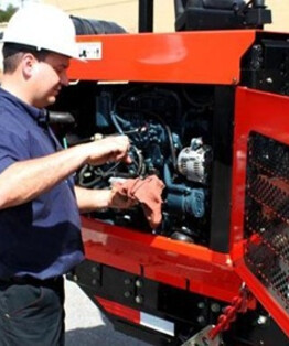
Если оборудование повреждено, его необходимо отремонтировать у сервисного партнера ПАЛФИНГЕРа.
В сервисную книжку установки должны быть занесены все ремонтные работы. В случае ремонта не у сервисного партнера ПАЛФИНГЕРа обязательства по гарантии утрачивают силу.
Примерный список неисправностей КМУ и методы их устранения приведены ниже:
Признак неисправности
Вероятная причина
Способы устранения
В гидросистеме нет давления.
- На входном разъеме клапана аварийного нет питания, остановка КМУ.
- Запорный кран закрыт на сливном патрубке бака.
- В баке отсутствует требуемое количество масла.
- КОМ или гидронасос не работает.
Нужно обратиться в сервисный центр.
В баке масло вспенивается, происходит выброс масла через сапун.
- На линии всасывания происходит подсос воздуха.
В гидросистеме снижено давление масла, установка не поднимает заявленные грузы и веса.
- Предохранительные клапаны разрегулированы.
В гидросистеме происходит пульсация масла, установка работает неровно, рывками.
- Пришел в негодность гидронасос или привод гидронасоса.
Наблюдается опускание груза самопроизвольно.
- Клапан удержания груза разрегулирован
- Уплотнения изношены
КМУ самопроизвольно движется при нейтральных положениях рычагов управления.
- Свойства вязкости масла не отвечают указанным в РЭ.
- В системе есть воздух.
- Разрегулирована или повреждена пружина секции гидрораспределителя или золотника.
Масло течет в соединениях рукавов высокого давления, трубопроводов.
- Резьбовые соединения слабо затянуты.
Масло течет через уплотнения штока.
- Изношены или повреждены уплотнения штока.
НУЖНО НЕМЕДЛЕННО ОСТАНОВИТЬ РАБОТУ КМУ!
Необходимо обращение в сервисный центр.
Видны трещины основного металла, а также сварных соединений основания КМУ, балок аутригеров, стрел.
- КМУ перегружена.

Отсутствие защитных средств, трещины или повреждения деталей КМУ, грузозахватных приспособлений могут привести к тяжелым последствиям.
Специалисты ПАЛФИНГЕРа советуют применять масло, биологически разлагаемое. Но даже такое вещество не должно попадать в окружающую среду.
Источник
Статьи по ремонту
Конструкция КМУ Palfinger
Конструкция КМУ Palfinger
КМУ Palfinger PK 15500/23500 предназначена для производства погрузо-разгрузочных, строительно-монтажных работ.
Иные операции, как-то: толкание или забивание объектов, крепление грузов на стреле в не предназначенных для этого местах, волочение груза по земле и другие подобные операции строго запрещены.
Производитель не несет ответственности за повреждения, вызванные такими действиями. Перемещение людей разрешается только в предусмотренной для этой цели рабочей корзине (люльке).
КМУ Палфингер РК 15500/23500 может эксплуатироваться при температуре от — 40 до +50 градусов Цельсия и при скорости ветра не более 14 м/с. (Климатическое исполнение – У, категория размещения 1 по ГОСТ 15150-69; 1-3 ветровой район России в соответствии с ГОСТ 1451-77). Уклон площадки — не более 3 град. Допустимый наклон крана-манипулятора при максимальном грузовом моменте — 5 град.
Основные компоненты КМУ Palfinger PK 15500/23500
Гидрораспределитель краноманипуляторной установки Palfinger PK 15500/23500
Гидрораспределитель служит для управления краноманипуляторной установкой Palfinger и представляет собой сборную конструкцию, которая, как правило, состоит из входной секции, четырех рабочих секций и выходной секции.
Входная секция предназначена для присоединения нагнетающей, сливной и управляющей магистралей гидросистемы к распределителю. В ней расположен главный предохранительный клапан, который служит для предохранения гидросистемы КМУ от перегрузки.
Кроме того, в этой же секции гидрораспределителя находится электромагнитный клапан аварийного отключения КМУ Palfinger. Четыре рабочие секции золотникового типа служат непосредственно для управления гидроцилиндрами крановой установки.
Каждая секция имеет дополнительные клапаны портов, которые регулируют давление в магистралях и предохраняют их от перегрузки.
Выходная секция гидрораспределителя служит для присоединения двух распределителей управления опорами крановой установки, соединенных последовательно.
Аутригеры и опоры КМУ Palfinger 15500/23500
Балки аутригеров КМУ Palfinger сварные, прямоугольного сечения, двигаются в основании на поддерживающих роликах и фиксируются в конечных положениях фиксирующим устройством.
Для предотвращения самопроизвольного выдвижения балок, фиксаторы имеют дополнительную блокировку, исключающую их открытие.
К наружным сторонам балок приварены монтажные фланцы, к которым с помощью болтов прикреплены цилиндры опор.
Основание, механизм поворота и колонна КМУ Palfinger PK 15500/23500
Основание КМУ Палфингер представляет собой трехопорную сварную конструкцию из высокопрочной конструкционной стали, к которой крепятся все остальные детали. В поперечную балку основания с двух сторон вмонтированы балки аутригеров.
К центральной части основания крепятся гидроцилиндры механизма поворота (либо гидромотор(ы) поворота колонны) и смонтирована колонна.
Основание краноманипуляторной установки крепится на монтажной установочной раме автомобиля (подрамнике/надрамнике) с помощью шпилек из высокопрочной легированной стали.
Механизм поворота КМУ Palfinger 15500/23500 состоит из двух гидроцилиндров одностороннего действия (или гидромотора), прикрепленных непосредственно к основанию, зубчатой рейки, с закрепленными на ней поршнями и шестерни, изготовленной как одно целое с колонной.
Колонна КМУ Палфингер представляет собой сварную конструкцию коробчатого сечения из высокопрочной стали. Нижняя часть колонны кованая, круглого сечения выполнена как одно целое с шестерней механизма поворота.
В нижней части коробчатой конструкции имеются проушины для крепления цилиндра подъема первой стрелы, а в верхней части — проушины для крепления первой стрелы. Колонна конструктивно нижней частью вставляется в основание КМУ и вращается в нем на подшипниках скольжения.
Стрела краноманипуляторной установки Palfinger
Первая стрела КМУ Palfinger коробчатого сечения сварена из высокопрочной конструкционной стали. Крепится корневой частью шарнирно к колонне посредством пальца и приводится в движение цилиндром подъема первой стрелы. Все шарнирные соединения снабжены подшипниками скольжения и имеют точки смазки.
В нижней части боковых щек имеются проушины для крепления цилиндров подъема первой и второй стрел. К концевой части первой стрелы манипулятора шарнирно присоединена корневая часть второй стрелы.
Вторая стрела КМУ Палфингер 15500/23500 представляет собой трубу шестигранного профиля, сваренную из высокопрочной конструкционной стали.
К концевой части второй стрелы приварен кронштейн для крепления цилиндра выдвижения удлинителей стрелы и проушина для крепления грузозахватных приспособлений.
В передней части второй стрелы имеются отверстия для крепления подшипников скольжения (скользунов), по которым двигаются секции удлинителей.
Удлинительные телескопические секции стрелы КМУ Palfinger представляют собой трубы шестигранного сечения, каждая из которых имеет меньшее сечение, чем предыдущая.
К концевым частям каждой секции приварены проушины для крепления цилиндров выдвижения секции и подвески грузозахватных приспособлений. В корневой части каждой секции установлены скользуны для уменьшения сил трения.
На КМУ Palfinger 15500/23500 установлены указатели наклона пузырькового типа. Они расположены на основании КМУ возле пультов управления.
На крановой установке в районе пультов управления установлены таблички грузоподъемности, которые информируют оператора о грузоподъемности на определенном вылете стрелы.
Гидросистема КМУ Palfinger
Гидробак КМУ Palfinger PK 15500/23500 представляет собой герметичную емкость сложной формы с рабочей жидкостью, снабженную фильтром низкого давления, сапуном, смотровым окном, выполненным как одно целое с указателем температуры рабочей жидкости, и всасывающим трубопроводом с шаровым краном.
Для слива рабочей жидкости гидробак имеет сливную пробку. Как правило, бак установлен непосредственно на основании КМУ и расположен выше всасывающего патрубка гидронасоса.
Фильтр низкого давления гидросистемы КМУ Палфингер РК 15500/23500 предназначен для очистки рабочей жидкости и установлен на линии слива непосредственно в маслобаке. Он состоит из корпуса, крышки, фильтрующего элемента с перепускным клапаном.
Фильтр имеет степень очистки 40 мкм. При засорении фильтрующего элемента и повышении давления в корпусе фильтра открывается перепускной клапан, и гидравлическое масло сливается в бак без фильтрации. Для контроля загрязненности фильтра на крышке смонтирован штуцер для установки контрольного манометра-индикатора.
Смещение стрелки манометра в красную область шкалы (> или = 1,6 бар) свидетельствует о необходимости замены фильтра. Работать с засоренным фильтром запрещено. Засоренные фильтры не промываются, а заменяются новыми.
Фильтр высокого давления гидравлической системы КМУ Palfinger предназначен для очистки рабочей жидкости и установлен на линии нагнетания сразу после гидронасоса. Он состоит из прочного корпуса, установленного на основании КМУ, и фильтрующего элемента со степенью очистки 10 мкм.
В крышке корпуса установлен предохранительный клапан, который перепускает рабочую жидкость в систему, если фильтрующий элемент засорится.
Обслуживание фильтра заключается в периодической замене фильтрующего элемента и очистке корпуса фильтра. Промывка фильтрующего элемента не допускается.
В КМУ Palfinger применены гидроцилиндры двустороннего действия. Гидроцилиндр двустороннего действия представляет собой цилиндр с приваренным с одной стороны днищем с проушиной.
С противоположной стороны цилиндр закрыт резьбовой крышкой со сквозным отверстием для прохода штока. Через сквозную крышку проходит шток, на одном конце которого закреплен поршень, а на другом — оголовок или проушина.
К гидроцилиндрам опор двустороннего действия КМУ Палфингер приварены монтажные пластины, с помощью которых они крепятся к балкам аутригеров или к крепежным элементам колонны и стрел. В нижней части штока цилиндра аутригера установлена опорная тарелка (подпятник).
Все составные части гидросистемы крановой установки соединены между собой трубопроводами, выполненными из бесшовных труб высокого давления, или резиновыми рукавами с двойной металлической оплеткой.
Счетчик моточасов КМУ Palfinger
На счетчике моточасов Вы можете увидеть индикацию общего количества работы КМУ Palfinger PK 15500/23500 в часах и количество часов до следующего технического обслуживания.
Счетчик моточасов отсчитывает наработку, начиная с 1000 м/ч в обратную сторону до 0. Затем он считает с отрицательным знаком от 0 (-1, -2, -3 и т.д.). После того, как Вы включили кран (электропитание) на дисплее на 10 секунд будет индицироваться общее количество рабочих моточасов крана.
Через 10 секунд Вы увидите на дисплее количество рабочих часов до следующего сервиса. Через каждый 50 часов (950, 900, 850 и т. д.) крановщик должен проводить техническое обслуживание КМУ Палфингер РК 15500/23500.
Когда достигаются последние 100 моточасов перед сервисом, дисплей начинает и продолжает мигать, пока показания не дойдут до 0. Сервис необходимо проводить при приближении 0 моточасов.
Если КМУ Palfinger работает менее 1000 часов в году, то необходимо посещать сервисную станцию и проводить техническое обслуживание не менее одного раза в календарный год.

Рис. 1. Счетчик моточасов краноманипуляторной установки Palfinger.
Источник
Техническое обслуживание
По всем вопросам, связанным с техническим обслуживанием и ремонтом оборудования PALFINGER просим Вас обратиться в КРУГЛОСУТОЧНУЮ горячую линию технической поддержки PALFINGER.
Горячая линия
СТАТЬ ДИЛЕРОМ PALFINGER
Одной из важных задач на пути успеха PALFINGER по всему миру является непрерывный процесс совершенствования грузоподъемных решений для конечных потребителей в какой отрасли они бы ни работали. Но выполнение данной задачи невозможно без надежного канала обратной связи от тех, кто ежедневно имеет дело с нашей продукцией. Поэтому региональные дилеры и сервисные партнеры в России и странах СНГ, с которыми концерн работает бок о бок уже много лет, являются важным звеном между PALFINGER и конечными потребителями.
Если Ваша компания заинтересована стать официальным дилером или сервисным центром ПАЛФИНГЕР СНГ, просим Вас заполнить соответсвующую заявку, нажав на кнопку ниже.
РЕГЛАМЕНТЫ ТЕХНИЧЕСКОГО ОБСЛУЖИВАНИЯ ОБОРУДОВАНИЯ PALFINGER
К обслуживанию оборудования PALFINGER могут быть допущены лица не моложе 18 лет. К эксплуатации поднадзорного Ростехнадзору оборудования (краны-манипуляторы, манипуляторы для металлолома/мусора, автогидроподъёмники, возимые вилочные погрузчики и т.д.) допускаются лица, прошедшие медицинское освидетельствование и прошедшие подготовку в профессионально-технических учебных заведениях, а также на курсах и в технических школах обучения, располагающих базой для теоретического и практического обучения и имеющих разрешение (лицензию) органов Ростехнадзора.
Подготовка рабочих должна осуществляться по программам, согласованным с Ростехнадзором России.
Мы рекомендуем использовать гидравлические масла стандарта не ниже HLP/ISO.
При выборе типа масла следует принимать в расчет, что вязкость варьируется в широких пределах в зависимости от температуры.
Источник
ЭКСПЛУАТАЦИОННАЯ ДОКУМЕНТАЦИЯ
В этом разделе Вы можете скачать различную эксплуатационную документацию по подъемному оборудованию PALFINGER. Раздел периодически пополняется и обновляется.
Если у Вас есть предложения по содержимому раздела, пожалуйста, обращайтесь в сервисную службу (контакты указаны справа).

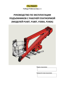
Руководство по эксплуатации КОЛЕНЧАТЫХ КМУ

РУКОВОДСТВО ПО ЭКСПЛУАТАЦИИ ТРОСОВЫХ КМУ

РУКОВОДСТВО ПО ЭКСПЛУАТАЦИИ КМУ PALFINGER

Руководство по эксплуатации КМУ оборудованной рабочей платформой (люлькой)

Руководство по эксплуатации КМУ, оснащенной лебедкой

РУКОВОДСТВО ПО ЭКСПЛУАТАЦИИ ТРОСОВОГО КРАНА-МАНИПУЛЯТОРА SPS 8500 HT
РУКОВОДСТВА ПО ЭКСПЛУАТАЦИИ гидроманипуляторов PALFINGER

Руководство по эксплуатации гидроманипуляторА EPSILON

Руководство по эксплуатации ГИДРОМАНИПУЛЯТОРА ВЕЛМАШ
Руководства по эксплуатации крюковых погрузчиков PALFINGER

Руководство по эксплуатации крюковых погрузчиков ПИОНЕР

РУКОВОДСТВО ПО ЭКСПЛУАТАЦИИ КРЮКОВЫХ ПОГРУЗЧИКОВ
РУКОВОДСТВА ПО ЭКСПЛУАТАЦИИ АГП PALFINGER
Руководство по эксплуатации ПРП PPI

Руководство по эксплуатации РЭ ВА 180 Т
РУКОВОДСТВА ПО ЭКСПЛУАТАЦИИ гидробортов PALFINGER

РУКОВОДСТВО ПО ЭКСПЛУАТАЦИИ ГИДРОБОРТОВ MBB
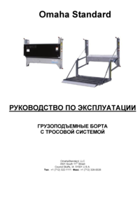
Руководство по эксплуатации гидробортов Омаха
Порядок заполнения сервисной книжки для корректной постановки оборудования PalfingeR на гарантийный учет