Please note:
• Safety-oriented input signals must operate in normally energised mode.
• Make sure that in the user program the «0»-Signal of the module will
switch-off the relevant outputs.
• Connecting one «0 V»-terminal is sufficient.
• Neighbouring inputs must not be assigned the same pulse.
• Copper wiring should be used that can withstand temperature of 75 °C.
• Torque setting on the screw terminals should be to 0.5 … 0.6 Nm.
Faults
If a fault in one of the modules or a wiring-error is detected, the controller
goes into a STOP condition, switches off all the outputs and sends a
message to the display. The display on the programmer’s error stack can
be used to locate the error.
Operating Manual
3
List of Pilz PSS Series Guides:
Guidesimo.com webproject is not a service center of Pilz trademark and does not carries out works for diagnosis and repair of faulty Pilz PSS Series equipment. For quality services, please contact an official service center of Pilz company. On our website you can read and download documentation for your Pilz PSS Series device for free and familiarize yourself with the technical specifications of device.
More Safety Equipment Devices:
-
Ansell MICROGARD 701 PAPR
MICROGARD LimitedHead Office9 Saltmarsh CourtPriory Park · HessleKingston upon Hull United Kingdom HU4 7DZTel +44 (0) 1482 625444 Fax +44 (0) 1482 630400Email [email protected] 701 Instructions for UseVersion 11.02.19EC Type Examination conducted by SGS Fimko Oy, P.O. Box 30 (Särkiniementie 3), 00211 HELSINKI, Finland. Notified Body CE 0598 …
MICROGARD 701 PAPR Safety Equipment, 90
-
BGS technic 3620
BGS technic KGBandwirkerstr. 342929 WermelskirchenTel.: 02196 720480Fax.: 02196 [email protected]© BGS technic KG, Vervielfältigung und Weiterverwendung verbotenArt. 3620 Atemschutzmasken ACHTUNG Lesen und verstehen Sie alle Anweisungen und Informationen in dieser Bedienungsanleitung. Die Nichtbeachtung der unten aufgeführten Anweisungen und Informationen kann zu sch …
3620 Safety Equipment, 9
-
Lumiance INSAVER 225
INSAVER 225 HE EMERGENCY CONE3111-447 (190308)min. Amin. B100min. C A B CInsaver 225 2×18 500 980 150Insaver 225 2×26 500 980 150Ø 228 +/-2Min 1 — Max 25min. 4 x 0,75 mm 2min. 4 x 1,5 mm 2840N L LUNSWITCHEDMAINSSWITCHEDMAINS2x Fuse F2H 250V SandfilledN L LNL L2311325 64b4a4c21Insaver 225 2x18WTC-D 18W G24-q2Insaver 225 2x26WTC-D 26W G24-q3213Click (3x) …
INSAVER 225 Safety Equipment, 2
-
Fbt LIGHT
VAIE 5500FBT ELETTRONICA S.p.A. — Via Paolo Soprani, 1 — ZONA IND. SQUARTABUE — 62019 RECANATI (MC) — ITALYTEL. 071750591 r.a. — FAX 0717505920 — P.O. BOX 104 — E-mail: [email protected] — www.fbt.it INSTRUCTIONS FOR USEVAIE 5502500W / 2 ZONES“LIGHT” Wall-mounted voice evacuation system …
LIGHT Safety Equipment, 44
Recommended Documentation:
Я не понял, про какую батарейку Вы имели ввиду.
Теперь все ясно.
У Вас их две.
Одна находится в главном компьютере — DELEM 65TW. Она питает BIOS материнской платы. Если эта батарейка садится, то сбрасывается CMOS, и параметры BIOS возвращаются к заводским настройкам.
Я разбирал DELEM 65W, там стоит ноутбучная материнская плата для процессора CELERON с пассивным охлаждением. Поэтому, если села эта батарейка, ничего страшного не произойдет.
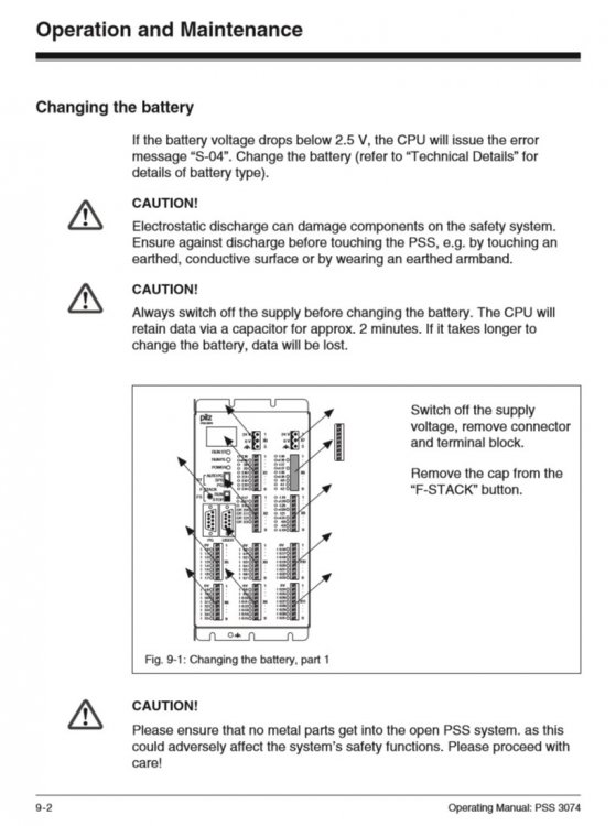
А вот со второй сложнее. Она питает программируемое защитное реле PILZ. Когда напряжение на батарейке станет 2.5, появляется предупреждение S04. Заменить батарейку требуется за 2 мин., иначе все данные будут уничтожены.
Покупайте новую батарейку, и замените ее при выключенном питание не более, чем за 2 мин.
Удачи.
Войти или зарегистрироваться
Контроллер безопасности Pilz (PSS 3074).
Тема в разделе «WASM.HARDWARE», создана пользователем 4ygynOK, 30 окт 2011.
-
4ygynOK
New Member
- Публикаций:
-
0
- Регистрация:
- 2 апр 2010
- Сообщения:
- 5
Форумчане требуется документация по этому устройству, желательно конечно на русском, но на любых других языках тоже приветствуется. Особенно буду рад по документации об ошибках, их расшифровка и т.п.
Может кто с ними уже работал, какие могут возникать проблемы и как их устранять. В общем любая информация приветствуется.
P.S. Заранее спасибо.
4ygynOK,
30 окт 2011
#1
(Вы должны войти или зарегистрироваться, чтобы ответить.)
- Ваше имя или e-mail:
- У Вас уже есть учётная запись?
-
- Нет, зарегистрироваться сейчас.
- Да, мой пароль:
-
Забыли пароль?
-
Запомнить меня

Поиск
-
- Искать только в заголовках
- Сообщения пользователя:
-
Имена участников (разделяйте запятой).
- Новее чем:
-
- Искать только в этой теме
- Искать только в этом разделе
- Отображать результаты в виде тем
-
Быстрый поиск
- Последние сообщения
Больше…
Modular Block System: Emergency Stop Circuits
6-25
The acknowledgements
FbL1 and FbL2 are also monitored in the static
condition. If there are discrepancies between the set and true condition, an
error message will be issued (
ENBL = 0) and the contactors will be
switched off immediately (
K1 = 0 and K2 = 0). The error will need to be
reset.
It is possible to reset errors via the input parameter
RSET both when ON =
0 and when
ON = 1. However, a prerequisite for setting the enable and,
when
ON = 1, switching on the contactors, is that the signals from the
feedback loops are correct.
Error messages
Any fault that is detected will be stored in the corresponding error data
word (
SSNR) of the administration data block (1st data block), until the
fault has been fully dealt with.
• Error messages in the administration data block
— Bit 00:
Fault as the signal changes at input parameter
ON,
feedback loop 1 (
FbL1) remains open
Remedy: Check contactor, contacts, cable, input card, output
card, value of input parameter
TFbL and all conditions and
then reset (input parameter
RSET)
— Bit 01:
Fault as the signal changes at input parameter
ON,
feedback loop 1 (
FbL1) remains closed
Remedy: Check contactor, contacts, cable, input card, output
card, value of input parameter
TFbL and all conditions and
then reset (input parameter
RSET)
— Bit 02:
Fault as the signal changes at input parameter
ON,
feedback loop 2 (
FbL2) remains open
Remedy: Check contactor, contacts, cable, input card, output
card, value of input parameter
TFbL and all conditions and
then reset (input parameter
RSET)


