
Safety output
Q2, Q3:
Output voltage tolerance:
Q0, Q1, (Q4, Q5):
Pluto O2: Q0, Q1:
13-14, 23-24
33-34
Outputs, non-failsafe
IQ10, IQ11,..
Max load/output:
Max total load:
A20, B16, B20, S20, B22, D20
B46, S46, D45, B42 AS-i
Pluto AS-i
Current monitoring IQ16, IQ17 (Only Pluto A20)
Range
Accuracy
Solid state, -24V DC, 800mA
Supply voltage -1.5V at 800mA
Relay, AC-12: 250 V / 1.5 A
AC-15: 250 V / 1.5 A
DC-12: 50 V / 1.5 A
DC-13: 24 V / 1.5 A
Relay, AC-12: 250 V / 5 A
AC-15: 250 V / 3 A
DC-12: 60 V / 5 A
DC-13: 24 V / 3 A
Relay, AC-12/AC-15/DC-12/DC-13: 24 V / 1.5 A
Solid state +24V, PNP open collector
Also configurable as failsafe inputs.
800 mA
IQ10..17: 2.5 A
IQ10..17: 2 A, IQ20..27: 2A
IQ10..13: 2 A
0-1.0 A
10%
46
2TLC172001M0211_A
- Печать
Страницы: 1 … 5 6 [7] 8 9 … 12 Вниз

Тема: Adalm Pluto SDR (Прочитано 21205 раз)
0 Пользователей и 1 Гость просматривают эту тему.
Олег, все железки «аля плуто» практически одинаковы по схемотехнике
У меня появился по оказии Плуто+, однако есть проблема — он всегда находтся в режиме передачи, на приём виден сигнал, который мешает. На выводе FPGA — MI00 всегда уровень 1,8в , что говорит о режиме ТХ в соответстии с прошивкой этого клона
Пятаюсь разобраться с прошивкой и собрать свою заново. Если есть какая либо информация, прошу поделиться
Прошивка текущая для Pluto+ = v0.32-1-g7bdc-dirty
GitHub = https://github.com/plutoplus

Записан
73! , Сергей
К сожалению не нахожу ответ на свой вопрос (ставший уже традиционным): как выглядит на прием начало диапазонов 144.000, 432.000 и 1296.000 ? Интересует наличие (отсутствие) спуров. Если можно — хотелось бы увидеть скрины.
Виктор,
пожалуйста, определите, что конкретно Вы хотели бы получить в результате измерений — дайте по инженерному максимально точно технические параметры условий измерений. Как будет время я постараюсь сделать.
Ответ можно в ЛС или если условия измерений требуют обсуждения — здесь.
Записан
Карен, RA3APW www.ra3apw.ru
Прошу прощения, это только мне одному кажется, что тема SDR трансивера «ADALM Pluto» как то странно соотносится с папкой «Программное обеспечение»?
Записан
Карен, RA3APW www.ra3apw.ru
Не только 
Записан
С уважением Павел
73!
RX6DT2(кот или собака)gmail.com
Можно перенести в соответствующую ветку.
Записан
73! Андрей RT3W
У меня появился по оказии Плуто+, однако есть проблема — он всегда находтся в режиме передачи, на приём виден сигнал, который мешает. На выводе FPGA — MI00 всегда уровень 1,8в , что говорит о режиме ТХ в соответстии с прошивкой этого клона
Сергей,
PLUTO дуплексный приемопередатчик.
Т.е. прием и передача одновременно.
Это особенно удобно при разнесенных частотах.
При симплексной работе на ОДНОЙ частоте на ПРИЕМ, видимо, нужно программно: — либо отключать передатчик,
— либо уводить его частоту в сторону, скажем, на 10кГц.
Олег, все железки «аля плуто» практически одинаковы по схемотехнике
… в соответстии с прошивкой этого клона
У вас какой-то «левый» PLUTO, схемотехника «поехала», возможны программные несовместимости и т.д
Записан
Владимир,
ex UC2CED, EU2CED, RC2CA, EU2CA
2019 год — https://observablehq.com/@eu2aa
2017 год — http://eu2aa.com
1992 год — http://eu2aa.qrz.ru
Владимир, понятно что и плуто левый а не правый) и конечно в любом случае режимы должны быть управляемые. Однако прошивка базируется на родной прошивке от плуто + патчи для Linux DTS.
В патчах комментариев нет, поэтому разбираю шаг за шагом где «косяк». И что самое неприятно, автор не отвечает пока.
Записан
73! , Сергей
Имею в своей коллекции и такой же вариант Pluto +, проблем не замечал. Разработчик отвечает на вопросы в твиттере ( глубоко в переписку не вдавался, но на мои вопросы отвечал). Так же вот и в Ютубе обзор появился
https://youtu.be/higdhj46aUk
Записан
Уважаемые, у меня тогда вопрос. Кш на прием (или чувствительность) на 1280/5800 МГц и уровень выхода на 1280/5800 МГц какой? Смотрю давно на эту штуку, но жаба душит пока. Даташит на чип смотрел, но вроде он патченый получается.
Записан
aka RK3X
Уважаемые, у меня тогда вопрос. Кш на прием (или чувствительность) на 1280/5800 МГц и уровень выхода на 1280/5800 МГц какой? Смотрю давно на эту штуку, но жаба душит пока. Даташит на чип смотрел, но вроде он патченый получается.
Работаю на Плуто в эфире почти 2 года,
вылизал оптимальные настройки.
В Кубке Гагарина — 101QSO, в Челленже 15-16 мая по числу QSO не отстал от лидеров ,
можно сказать, что Плуто освоил.
Выше 4,3ГГц начинает падать выход и слабеют шумы приемника. Кшума — не измерял, но прием заметно тупеет.
В декабре понадобилось прослушать маяк 5760,800МГц.
Неожиданно обнаружил, что выше 5749,989МГц накрутить не получается.
Не пускает.
В настройках LPF лучше, когда 200кГц.
Прилагаю скрин.
Насел на проблему, все таки выкрутил 5760МГц, без нескольких Килогерц,
но какой ценой?
Полностью разрушив все оптимальные настройки.
До частоты маяка 5760,800МГц так и не дотянулся…
Прослушал, но с конвертером.
*кстати, JA1SYK тоже выше 5759,998МГц не смог.
**конечно, можно устроить Плуто расширение не до 6000МГц, а, скажем, до 6,1ГГц.
Тогда частоты 5760++ удастся выставлять при оптимальных настройках.
***будет время, исследую на верхних частотах поподробнее
« Последнее редактирование: 16 Июнь 2021, 23:25:59 от EU2AA »
Записан
Владимир,
ex UC2CED, EU2CED, RC2CA, EU2CA
2019 год — https://observablehq.com/@eu2aa
2017 год — http://eu2aa.com
1992 год — http://eu2aa.qrz.ru
уровень выхода на 1280/5800 МГц какой?
Измерил у моего экземпляра уровень выхода на разъеме ТХ:
144,078 — +2dBm,
432,078 — +7dBm,
1296,078 — +5dBm,
2400,078 — +3dBm,
5760,078 — +1dBm.
Режим SSB, однотоновый сигнал 1кГц, нч-уровень, близкий к ограничению.
Реально SSB, модулированный голосом, даст выходной уровень меньше, представляется, на децибел 10.
*передатчик можно настроить до 6000МГц ВКЛЮЧИТЕЛЬНО. На 6,0ГГц — +1dBm.
**вот приемник — нет. LPF=200kHz или что-то еще не пускает.
Соответственно, в трансиверном режиме, такое же ограничение.
« Последнее редактирование: 17 Июнь 2021, 00:38:19 от EU2AA »
Записан
Владимир,
ex UC2CED, EU2CED, RC2CA, EU2CA
2019 год — https://observablehq.com/@eu2aa
2017 год — http://eu2aa.com
1992 год — http://eu2aa.qrz.ru
Спасибо, Владимир! С приемником засада, конечно. Буду читать.
Записан
aka RK3X
Всем добрый день. Вчера попробовал подключить к Pluto трансвертер VK3XDK, в котором убрал смеситель hmc213, после 2 каскадов rx в трансвертере подал на вход Pluto. В качестве источника сигнала использовал adf4350 на 2880 МГц. 2 гармонику увидел.
Записан
73! Андрей RT3W
1. Pluto+ с своей прошивкой работает в режиме USB и в режиме Ethernet
2. Pluto+ с оригинальной прошивкой от ADI для ADALM Pluto работает в режиме USB
3. Пока не удалось запустить Pluto+ в режиме работы непосредственно через Ethernet с ПО SDRAngel
https://github.com/f4exb/sdrangel
4. Измерил у своего Pluto+ уровень выхода
ПО — SDR Console V3.027
FW Pluto+ = Hack, ver 0.33
145Mгц = ~+8дбм
5999МГц = ~+7дбм
Достаточно много внеполосных излучений, оптимальный максимальный уровень выхода = ~0дбм
5. Чувствительность не измерял, но видно, что выше 3Ггц она падает. Надеюсь на этой неделе проведу измерения
с Кареном RA3APW(TKS)
6. есть особенности ПО СДР:
а. спур на центральной частоте обзора — для Pluto+ уровень сш в SDR Console =~+12-14дб
б. из-за особенностей чипов AD93XX неотключаемый передающий тракт — наличие видимой несущей на рабочей
частоте приёма в симплексном режиме
для минимизации эффекта б. — использовать функцию Offset в SDR Console
для минимизации а. добавить предусилитель по входу = > 15дб
6. Ховард(автор ПО для Pluto+ на GitHub) скомпилировал оригинальную версию ADI FW ver 0.33 для Pluto+
https://github.com/plutoplus/plutoplus/releases
— Support Ethernet out of box
— Add the additional packages required for DATV:
gpsd, php, ffmpeg, alsa, x264, fftw, libv4l, nfs
однако не работает Python server, будет выпущено обновление скоро
7. Ховард начал активную переписку с F5OEO (https://github.com/F5OEO/datvplutofrm) для имлементации полной поддержки DATV в Pluto+
Если у кого есть наработки и иные замечания прошу поделиться
Готовлюсь к реализации https://observablehq.com/@eu2aa/eu2aa4b-n-1?collection=@eu2aa/sdr
« Последнее редактирование: 22 Июнь 2021, 13:28:37 от r5au »
Записан
73! , Сергей
Готовлюсь к реализации https://observablehq.com/@eu2aa/eu2aa4b-n-1?collection=@eu2aa/sdr
не стоит, на выходе шестидиапазонный вариант с одним плуто
Записан
Владимир,
ex UC2CED, EU2CED, RC2CA, EU2CA
2019 год — https://observablehq.com/@eu2aa
2017 год — http://eu2aa.com
1992 год — http://eu2aa.qrz.ru
- Печать
Страницы: 1 … 5 6 [7] 8 9 … 12 Вверх
Машина VE-2300. Pluto B46-6. Error 50
-
Цитата
#1
Сообщение
demiurg1978 » 05 июн 2017, 07:40
Клиент купил станок. При подключении на панели оператора сообщение «Аварийная остановка робота». Pluto сначала выдавал ошибку «Er 52» теперь выдает «Er 50».
Скажите, пожалуйста, что это за ошибки? Есть ли мануал со списком и расшифровкой ошибок? Если проблема аппаратная (сам Плуто), что можно сделать?
Вскрытие показало, что в Плуто ковырялись. Перепаяны электролиты.
-
Contents
-
Table of Contents
-
Bookmarks
Quick Links
Original instructions
PLUTO
Safety-PLC
Operating instructions
Hardware
English v11A
2TLC172001M0211_A
Related Manuals for ABB PLUTO Safety-PLC
Summary of Contents for ABB PLUTO Safety-PLC
-
Page 1
Original instructions PLUTO Safety-PLC Operating instructions Hardware English v11A 2TLC172001M0211_A… -
Page 2: Table Of Contents
Table of contents: General ……………………..4 Enclosure ……………………. 5 Electrical installation ………………….5 Inputs and outputs ………………….6 I.. Digital failsafe inputs ………………..12 IQ.. Digital failsafe inputs / Digital outputs (non failsafe) ……….13 4.2.1 Dynamic signals ………………….13 4.2.2 Current monitoring IQ16, IQ17 (Only A20) …………..
-
Page 3
Connection examples ………………… 35 Example of applications ………………..38 Pluto bus communication ………………..39 Bus cabling ……………………39 9.1.1 Cable length ……………………40 9.1.2 Connection of bus cable shield ………………40 9.1.3 Optional protection against conducted disturbances …………41 Response time over the bus ………………. 41 Identifier ……………………. -
Page 4: General
1 General Pluto is a programmable safety system intended for safety applications where it is not accepted that faults in the control system lead to loss of a safety function. To achieve this requirement the system is designed with integral redundancy and monitoring. Unlike ordinary PLC systems, Pluto utilizes two microprocessors, which both control and monitor each safety function for correct operation.
-
Page 5: Enclosure
2 Enclosure Pluto is constructed in an enclosure for snap mounting on a DIN-rail in control cabinets or other suitable enclosures. External wiring is connected via screw terminals. To make it easy and to avoid incorrect connection when a unit is exchanged, the connector blocks are detachable so that individual wires do not have to be disconnected.
-
Page 6: Inputs And Outputs
4 Inputs and outputs In order to be as flexible as possible Pluto offers various combinations of different I/O: s. There are also different families and types of PLUTO. Pictured below are the IO overviews for the various Pluto types. Transistor output, individual failsafe Inputs, individual failsafe…
-
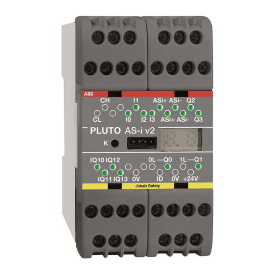
Page 7
Transistor output, Inputs, individual failsafe individual failsafe Pluto bus 0-10V/4-20mA Pluto D20 0-24V IQ10 IQ11 IQ12 IQ13 IQ14 IQ15 IQ16 IQ17 0V +24V Identifier Power Failsafe inputs / Indication outputs (not failsafe) / Dynamic outputs Relay output, input individual failsafe I/O overview PLUTO D20 Inputs and outputs for Pluto D20 Terminal on Pluto… -
Page 8
Inputs, individual failsafe Inputs, individual failsafe Inputs, individual failsafe Digital/Analogue SR41 SR45 SR46 +24V Power Pluto B46, S46 supply Identifier IDFIX Safety outputs Pluto bus IQ10 IQ11 IQ12 IQ13 IQ14 IQ15 IQ16 IQ17 IQ20 IQ21 IQ22 IQ23 IQ24 IQ25 IQ26 IQ27 Failsafe inputs / Outputs (not failsafe) / Dynamic outputs 1) Not S46-6… -
Page 9
Digital inputs, individual failsafe Analogue inputs 0-10V/4-20mA Inputs, individual failsafe Inputs, individual failsafe Fast counter DI AI DI AI DI AI DI AI DI AI DI AI +24V Power supply Pluto D45 Identifier IDFIX Safety outputs Pluto bus CS (Shield) IQ10 IQ11 IQ12… -
Page 10
Inputs, individual failsafe Inputs, individual failsafe Inputs, individual failsafe AS-Interface Digital/Analogue ASi+ ASi- SR41 SR45 SR46 +24V Power supply Pluto B42 AS-i Identifier IDFIX Safety outputs Pluto bus (Shield) IQ10 IQ11 IQ12 IQ13 IQ14 IQ15 IQ16 IQ17 IQ20 IQ21 IQ22 IQ23 IQ24 IQ25… -
Page 11
Power supply Inputs, individual failsafe CAN-bus AS-Interface Identifier input +24V ASI+ ASI- Pluto AS-i IQ10 IQ11 IQ12 IQ13 DI AI DI AI Failsafe inputs / Analogue inputs Safety outputs Outputs (not failsafe) / Dynamic outputs I/O overview PLUTO AS-i Inputs and outputs for Pluto AS-i Terminal on Pluto In-/Output name in software I/O type… -
Page 12: Digital Failsafe Inputs
Safe inputs Dynamic outp 24V, 1.5A 250VAC, 5A Non-safe outp IQ10 Pluto O2 Safety Output Module IQ11 +24V 0V Non-safe outp Power supply Dynamic outp 24V, 1.5A 250VAC, 5A Safe inputs I/O overview PLUTO O2 Inputs and outputs for Pluto O2 Terminal on Pluto In-/Output name in software I/O type…
-
Page 13: Dynamic Signals
IQ.. Digital failsafe inputs / Digital outputs (non failsafe) This type of IO-terminals provides 4 different functions. Each terminal is connected to both processors and may therefore be used as a failsafe input. Each terminal is also equipped with an output transistor giving the user the possibility to configure it as either a failsafe input or non failsafe output.
-
Page 14: Analogue Inputs
Analogue inputs 4.3.1 Analogue inputs 0-10V / 4-20mA (Pluto D20 and D45) Pluto D20 is equipped with 4, and Pluto D45 with 8, safe 4-20mA/0-10V analogue inputs. These (D20: IA0 – IA3, D45: IA0 – IA7) can be configured as either “ordinary” failsafe inputs, as analogue inputs 0-10V or as analogue inputs 4-20mA.
-
Page 15: Volt
4.3.1.2 0 Volt In general 0 or close to 0 volt/mA cannot be trusted as a true signal except when there is a dynamic behaviour in the application which makes it possible to evaluate the correctness. There are two reasons for this: 0 can be a consequence of an internal fault in Pluto.
-
Page 16: Connection Of Analogue Voltage Output Sensors (0-10V)
4.3.2.1 Connection of analogue voltage output sensors (0-10V) It is important that the 0V wire from the analogue sensor is connected directly to the terminal ”0V” on Pluto, and not to 0V somewhere else. Otherwise current in the 0V conductor may affect the measured analogue value.
-
Page 17: Counter Inputs Pluto D45
Counter inputs Pluto D45 For Pluto D45 the inputs IA0 – IA3 can be configured as counter inputs (pulse counting) which work for frequencies up to 14000 Hz. As counter inputs IA0 – IA3 can be used in two ways, Up counting or Up/Down counting.
-
Page 18: Up/Down Count
4.4.2 Up/Down count In order to determine the direction of a movement input IA0 and IA2 can be configured as Up/Down counters. When this is done the next input (IA1 or IA3) is automatically reserved for Up/Down counting. This means that for Up/Down counting IA0-IA1 are a pair and IA2-IA3 are another pair.
-
Page 19: Sensor Output Types
4.4.3 Sensor output types +24V +24V Push-pull / HTL sensor output. Open collector / PNP sensor output Typical for incremental encoders Typical for proximity sensors and photocells Incremental encoders with HTL output and other with push-pull output can be used at frequencies up to around 14 kHz.
-
Page 20: Speed Monitoring With One Sensor
Interruption in the cabling to a sensor will lead to that Pluto read 0-speed from that sensor. Such fault must therefore be detected in the application by using two independent sensors that are automatically cyclically checked with regard to that there is motion in the machine at least a couple of times per day.
-
Page 21: Possible Architectures, Achievable Safety Levels And Prerequisites
4.4.7 Possible architectures, achievable safety levels and prerequisites This table is an overview of safety levels for different applications. The achievable Cat / SIL / PL depends on the sensor which is used in the application and the detection capability of faults listed in IEC 61800-5-2, table D.16. Structure Usage Achievable…
-
Page 22: Failsafe Outputs
Failsafe outputs 4.5.1 Relay outputs Each potential free relay output is made individually “redundant” by the use of two series connected relay contacts controlled by each processor. A single output can be used to individually control a safety function, however the outputs cannot detect short circuits in e.g. connection cables.
-
Page 23: Test Pulses
4.5.2.1 Test pulses In order to make internal tests and to test against external short circuits the outputs Q2 and Q3 are cyclically switched off during 100..200 µs, so called test pulses. Principle for solid state safety outputs. Diagram showing output voltage with test pulses 4.5.2.1.1 Disabling of test pulses For Pluto A20 v2, B20 v2, S20 v2 and Pluto D20, the test pulses can be disabled via Pluto Manager.
-
Page 24: As-Interface Bus (As-I)
AS-Interface bus (AS-i) Only for Pluto AS-i and B42 AS-i As can be seen in the I/O overview Pluto AS-i has only 8 digital I/O but is equipped with connection for AS-i bus. AS-i is a standardised industrial bus where both power and data is transmitted via a two-wire cable.
-
Page 25: Reading Safety Slaves
4.6.2 Reading safety slaves The main intention with Pluto AS-i is to read and evaluate the safety slaves with its dual CPU. A standard slave can have 4 input variables which are read separately by the master. A safety slave has also 4 input variables, but physically only one single channel or dual channel input. The 4 input variables are used to send a safety code, unique for each slave.
-
Page 26: Modes Of Operation
Pluto as Safe Input This is the setting for a Pluto that is used as a safe input slave. A special function block, “PlutoAsSafeInput”, is needed for the PLC program. Configuration of the safe input and non- safe outputs are the same as for the ordinary “Safe input” slave. Pluto can handle up to 16 “PlutoAsSafeInput”…
-
Page 27: Connection Of Inputs
5 Connection of inputs Dynamic signals The IQ terminals can be configured as dynamic outputs, and be used for voltage supply of the input devices. If they are configured as dynamic, each of them generates a unique pulse train as shown in the diagram below. The system is intended for detection of different short circuits in external cabling, and dynamic monitoring of sensors.
-
Page 28: Connection Of In-/Outputs Iq
5.1.2 Connection of in-/outputs IQ.. The IO type IQ_ have some restrictions. If they are to be used as failsafe single channel inputs they must be configured as dynamic; A, A-inverse, B, B-inverse, C or C-inverse. For some two- channel devices also +24V can be used. Configured as dynamic output Dyn A, B or C The system does not accept…
-
Page 29: Connection Of Safety Devices
6 Connection of safety devices Dual channel systems The classic way of making a failsafe system is to use two-channel devices. The system offers various possibilities for connection of such devices. The figures below show solutions for connection of two channel devices. The first figure gives example of possible connections and the second shows the common connection of several dual channel safety devices.
-
Page 30: Single Channel Systems
Single channel systems Instead of using two-channel systems some applications can be made failsafe by using the principle of a dynamic single channel. By supplying electronic devices with dynamic signals a fault in the electronics will lead to a static on or off state at the input which will be detected immediately. By inverting the signal in or at the sensor, short circuits over the sensor are also detected.
-
Page 31: Monitoring Of External Short Circuit
Monitoring of external short circuit The system offers three main methods for avoiding that short circuit in input cabling leads to loss of the safety function. The drawing below illustrates the different methods by which emergency stop buttons can be connected. The first button has two NC contacts supplied by one dynamic signal and +24V.
-
Page 32: Safety Devices With Transistor Outputs
Safety devices with transistor outputs Certain safety devices on the market, i.e. light curtains, light beams, scanners etc., are designed with dual monitored safety 24V DC transistor outputs. These devices monitor the output circuits by making short interruptions in the output signals. Both channels can be connected to the system as static inputs.
-
Page 33: Two-Hand Control
Two-hand control Two-hand control devices can be realized in many ways depending on the contact configuration in the two-hand device and which Pluto inputs are used. Below are some examples of solutions. All of the examples shown fulfil the requirements for type IIIC according to EN 574.
-
Page 34: Illuminated Push Button Function
Illuminated push button function It is possible to connect both an indicator lamp and an input switch at the same time to IQ terminals, e.g. illuminated push button. A diode must be connected locally to the input device. The function is mainly intended for reset devices and reduces the number of IQ terminals used. Note that the output voltage is a square wave of 24 V amplitude and the effective voltage to the indicator is reduced to a mean value of 75%.
-
Page 35: Connection Of Outputs
7 Connection of outputs Below are examples of output connections that give different degrees of protection against short circuits. When and where they can be used depends on the kind of machine application (risk) and the electrical installation. Connection examples Output examples 1: Connection and monitoring of contactors.
-
Page 36
Output examples 2: Contact expansion with expansion relays and safety relay Monitoring Monitoring I_/IQ_ I_/IQ_ -24V +24V +24V (Minus) /IQ_ /IQ_ Test The examples give the same degree of safety and have the same advantages and disadvantages as output examples 1 and can be used for the same type of applications. Output examples 3: Short circuit protected Connection and monitoring of contactors with protection against short circuit, for applications with very high demands on safety integrity level. -
Page 37
Output example 4: Polarized safety relays Monitoring I_/IQ_ /IQ_ Test When using a safety relay for output expansion of output Q2 and Q3, the connection between the Pluto output and the safety relay is failsafe against short circuit from foreign +24V. This because it is operated by -24V and since the safety relay is polarized it cannot be switched on by +24V. -
Page 38: Example Of Applications
Example of applications 2TLC172001M0211_A…
-
Page 39: Pluto Bus Communication
Pluto bus communication Up to 32 Pluto units can be interconnected with CAN-bus. Communication is achieved by connecting a twisted pair cable to the CH and CL terminals. When this connection is made the Pluto units can read each other’s I/O. When the bus is connected each Pluto unit executes its own individual program and operates independently, however it can read other units I/O.
-
Page 40: Cable Length
9.1.1 Cable length The maximum cable length is depending on the bus speed. Data Trunk Distance Stub length Rate Units connected on a Stub must not have termination resistors fitted. Max single stub Accumulated stub length 100 kbit/s 600 m 25 m 120 m 125 kbit/s…
-
Page 41: Optional Protection Against Conducted Disturbances
9.1.3 Optional protection against conducted disturbances Conducted disturbances may cause problems with the Pluto bus communication. This problem might be solved by connecting a capacitor between 0V on Pluto Supply and earth. Please note that this connection is optional. It shall only be tried if there is a problem with the bus communication! IQ10 IQ11…
-
Page 42: Identifier
10 Identifier The identifier is an external component that can be connected to the “ID” and “0V” terminals. The circuit contains a unique ID-number that can be read by the system. In the PLC program the identifier number can be declared which connects the program so that it will only work together with the correct identifier.
-
Page 43
— The PLC program in IDFIX-PROG can be loaded into flash memory by pressing the K button in the same way as self programming over the CAN bus. This can be done when Pluto displays error message Er20 (No program loaded), Er24 (Erroneous PLC program) or Er31 (IDFIX-PROG program mismatch). -
Page 44: Programming
11 Programming The development of application programs (Pluto PLC program) is made with a standard Personal Computer using a specially developed software Pluto Manager. Communication between the PC and the Pluto is made via the PC Com Port or USB port. The link facilitates program down loading and monitoring of inputs, outputs, memory, timers, etc.
-
Page 45: Cleaning
12 Cleaning The front plate can be cleaned by a dry dust rag. The front plate can also be removed for cleaning or exchange. 13 Technical data Supply Nominal Voltage 24 V DC Tolerance +/-15% Max interruption 20 ms Recommended external fuse A20, B16, B20, S20, B22, D20, Pluto AS-i, O2: 6A B46, S46, D45, B42 AS-i: 10A Total current consumption…
-
Page 46
Safety output Q2, Q3: Solid state, -24V DC, 800mA Output voltage tolerance: Supply voltage -1.5V at 800mA Q0, Q1, (Q4, Q5): Relay, AC-12: 250 V / 1.5 A AC-15: 250 V / 1.5 A DC-12: 50 V / 1.5 A DC-13: 24 V / 1.5 A Pluto O2: Q0, Q1: 13-14, 23-24… -
Page 47
Indication: Input/Output LED’s Controlled by processor General Enclosure A20, B16, B20, S20, B22, D20, O2 and Pluto AS-i: 45 x 84 x 120 mm (w x h x d) B46, S46, D45 and B42 AS-i: 90 x 84 x 120 mm (w x h x d) Mounting DIN-Rail Response time of dynamic A or static input (+24V) -
Page 48
Safety parameters SIL according to EN 62061/IEC 61508 SIL 3 PL according to EN ISO 13849-1 PL e Category according to EN ISO 13849-1 according to EN ISO 13849-1 High CCF according to EN ISO 13849-1 Meets the requirements HFT (Hardware fault tolerance) >99% for the single channel parts SFF (Safe failure fraction) >90% for the double channel parts… -
Page 49: Connection Of Sensors
13.1 Connection of sensors Maximum number of sensors that can be connected in series with 100m cable: Eden Spot 35 Spot 10 Tina Maximum cable length, without sensors, for inputs using dynamic signals (depending on capacitance): Example 10×0.75 mm² = approx. 1000 meter 2TLC172001M0211_A…
-
Page 50: Appendix — Message And Fault Code List
14 Appendix — Message and fault code list Note: Reboot can either be made from PC computer or by power off-on. Status messages Description Power up Run mode (nn = station number) Program load mode state. Flashing ”Lo”, ready for self programming (program found in other unit). Program execution stopped from PC computer or not started after program download.
-
Page 51
I/O faults Fault and possible reason. Reset action Er40* Error safety output Q2 or Q3. “K” button Q2, Q3 connected together or to other negative voltage. Q2, Q3 has too high capacitive load. Er41* Error output Q2 or Q3. Overload or connected to foreign “K”… -
Page 52
AS-i Fault and possible reason. Reset action AE 01 ASi power missing. Automatically reset AE 02 No connection with ASi master (in Monitor mode). Automatically reset AE 03 Safety code missing by code teaching. Teach AS-i safety codes AE 04 Wrong code table. -
Page 53
Pluto O2 — Indicators Pluto O2 has 6 LED indicators instead of display. These have the following function. Indicator Description – Input on Flash – Two channel fault, generated by function block. Or power on input and program not loaded. –… -
Page 54
EC declaration of conformity ABB AB declare under our sole responsibility that the safety Jokab Safety components of ABB manufacture, with type designations Kanalvägen 17 and safety functions as listed below, are in conformity with SE-183 30 Täby the Directives… -
Page 55
ABB Ltd. Tel: +34 93 4842121 Produtos de Baixa Tensão Tel +353 1 4057 381 Fax: +34 93 484 21 90 ABB Atende: 0800 014 9111 Fax: +353 1 4057 312 Web: www.abb.es Fax: +55 11 3688-9977 Mobile: +353 86 2532891 Web: www.abb.com.br…
Осуществляем ремонт и восстановление JOKAB SAFETY PLUTO B46 V2 SAFETY-PLC 24+16+4+2 (20-070-17), part number 2TLA020070R1700 на уровне компонентов с применением новейшего высокоточного и высокотехнологичного оборудования.
По статистике, около 90% оборудования, признаваемого обычно неремонтируемым, подлежит восстановлению.
Преимущества ремонта JOKAB SAFETY PLUTO B46 V2 SAFETY-PLC 24+16+4+2 (20-070-17), part number 2TLA020070R1700 по сравнению с покупкой нового блока:
- Экономия времени (срок ремонта 15-20 рабочих дней)
- Экономия денежных средств (30-50% от стоимости нового блока)
- Не требуется дополнительная настройка/перепрограммирование
Инженерная компания «555» — лидер на рынке компонентного ремонта промышленной электроники:
- Крупнейшая лаборатория в России по ремонту промышленной электроники на компонентном уровне
- Международный сертификат стандарта IPC
- Более 10 000 отремонтированных электронных блоков
- Более 2 000 заказчиков от малого бизнеса до крупнейших корпораций
О ремонте
Видео о крупнейшей в России лаборатории по ремонту промышленной электроники. Узнайте, где выполняют ремонт станков, сервоприводов, частотных преобразователей и другой промавтоматики на компонентном уровне.
Срок ремонта
15-20 рабочих дней
Заявка на ремонт
Видеопрезентация Инженерной компании «555»
Заявка на ремонт
Постарайтесь подробно описать дефект!
Звоните +7 (800) 555-89-01
Работать с нами просто, схема взаимодействия
1

Консультация по телефону
2

Отправка оборудования на осмотр
3

Оценка стоимости ремонта
4

Оплата счета
5

Ремонт и отправка оборудования
1Консультация по телефону
2Отправка оборудования на осмотр
3Оценка стоимости ремонта
4Оплата счета
5Ремонт и отправка оборудования
Техническое обслуживание оборудования
Помимо ремонта, компания ik555 предлагает услугу по техническому обслуживанию оборудования нашими инженерами на вашем предприятии, либо в нашей лаборатории
- Крупнейшая лаборатория в России по ремонту промышленной электроники на компонентном уровне
- Международный сертификат стандарта IPC
- Более 10 000 отремонтированных электронных блоков
- Более 2 000 заказчиков от малого бизнеса до крупнейших корпораций
Подробнее


Компания ООО «Барс-Гидравлик Групп» на протяжении нескольких лет успешно сотрудничает с ООО «Инженерная компания 555» в вопросах ремонта сложного промышленного оборудования. За время работы наш партнер зарекомендовал себя с самой лучшей стороны. Заказы выполняются в кротчайшие сроки при соблюдении высокого качества работ. Организация приема и выдачи заказов четкая. Гарантийные обязательства выполняются в полном объеме.
Выражаем благодарность Вашим специалистам за профессионализм и оперативное решение поставленных задач.
Особенно хочется отметить высокую клиентоориентированность персонала Вашей компании, готовность помочь в самых сложных ситуациях.
Мы высоко ценим сложившиеся между нашими компаниями открытые и доверительные партнерские отношения и искренне желаем «Инженерной компании «555» долгих лет успеха и процветания.
Читать весь
отзыв

ООО «Инженерная компания «555» оказывала нашей компании услуги по ремонту электродвигателей и проявила пунктуальность, аккуратность и ответственность в работе.
Результат выполненных работ говорит о качественном оборудовании и высококвалифицированных кадрах.
Сотрудники компании готовы выполнить новые для себя виды работ и оказать консультационные услуги, что характеризует их как профессионалов своего дела.
Рекомендуем ООО «ИК «555» как ответственного и надежного поставщика услуг.
Читать весь
отзыв

Сообщаем, что наша организация сотрудничает с ООО «Инженерная компания «555» с мая 2016 года по настоящее время.
За этот период мы обращались к услугам компании более 10 раз.
Благодаря серьезному и квалифицированному подходу сотрудников ООО «Инженерная компания «555» ремонтные работы произведены качественно с учетом сроков, и обеспечены гарантийным сопровождением.
Планируем в дальнейшем работать с ООО «Инженерная компания «555»
Читать весь
отзыв

Уважаемый Дмитрий Васильевич!
ОАО «Октябрьский электровагоноремонтный завод» успешно работает с ООО «Инженерная компания «555» несколько лет, очень довольны данным сотрудничеством. В работе компании наибольшую ценность для нас представляет готовность работать на условиях, удобных Заказчику, качественный ремонт оборудования в заявленные сроки и самое главное, финансовая защищенность Заказчика. В инженерной компании работают внимательные, доброжелательные сотрудники, готовые в любой момент решить проблему Заказчика. Мы рады, что выбрали ООО «Инженерная компания «555» в качестве партнера. Гарантируем дальнейшее сотрудничество!
Читать весь
отзыв

ЗАО «Охтинское» выражает глубокую признательность и истинную благодарность ООО Инженерной компании «555» за качественную работу компании по ремонту сложного оборудования промышленной электроники, оперативность и технически грамотное отношение к работе в течении всего периода сотрудничества.
Мы надеемся на дальнейшее успешное развитие деловых отношений в сфере ремонта промышленной электроники.
Читать весь
отзыв
Преимущества сотрудничества с нами

Оплата только за результат — работающий блок

Гарантия на работоспособность блока целиком 12 месяцев

Срок ремонта от 5 до 15 дней

Бесплатный предварительный осмотр на предмет ремонтопригодности

Не вносим конструктивных изменений

Ремонт на компонентном уровне
Наша лаборатория расположена в Санкт-Петербурге, но обратиться за помощью вы можете из любой точки России.
Закажите обратный звонок или наберите в рабочее время многоканальный телефон
– +7 (800) 555-89-01 (звонок по России бесплатный).
Расскажите о своей проблеме и получите инструкцию к дальнейшим действиям.