
- Page 1
Renault CLIO Vehicle user manual… - Page 2
Renault cars. Lasting protection and optimum performance for your engine – guaranteed. Whether changing the oil or simply topping up, to find the approved ELF lubricant best suited to your vehicle, ask your Renault dealer for a recommendation or consult your vehi- cle maintenance handbook. - Page 3
Welcome to your new vehicle This driver’s handbook contains the information necessary: – for you to familiarise yourself with your vehicle, to use it to its best advantage and to benefit fully from the all the functions and the technical developments it incorporates. –… - Page 4
ExTErior Rear view mirrors ➥ 1.95 Electric windows ➥ 3.18 Windscreen wipers ➥ 1.105 and ➥ 1.110 Demisting ➥ 3.6 and ➥ 3.10 Key/Remote control ➥ 1.2 Map ➥ 1.6 Locking/unlocking the doors ➥ 1.13 Lights: operation ➥ 1.97 Bodywork maintenance ➥ 4.14 Lights: replacement ➥… - Page 5
PassEngEr comParTmEnT Adjusting your driving po- Passenger compartment storage, fit- sition ➥ 1.23 tings ➥ 3.24 Rear bench seat ➥ 3.31 Rear headrests ➥ 3.30 Front seats ➥ 1.21 Front headrests ➥ 1.20 Luggage compartment stor- Child safety ➥ 1.37 age/fittings ➥… - Page 6
DrivEr’s PosiTion Trip computer controls ➥ 1.77 Instrument panel ➥ 1.64 Exterior lighting ➥ 1.97 Multimedia screen ➥ 3.16 Cruise control ➥ 2.88 Heated seat(s) ➥ 1.21 Adaptive cruise control Stop and Go ➥ 2.93 Heating/Air conditioning Speed limiter ➥ 2.84 system ➥… -
Page 7: Driving Aids
Driving aiDs Speed limiter ➥ 2.84 ABS (anti-lock braking system) ESC (electronic stability control) Detection of road signs ➥ 2.80 Braking assistance Hill start assistance ➥ 2.36 Cruise control ➥ 2.88 Lane departure warning ➥ 2.41 Adaptive cruise control Stop and Go ➥…
- Page 8
safETy on boarD Front Airbags ➥ 1.28 Inhibiting the front passen- Curtain Airbags ➥ 1.35 ger airbag ➥ 1.57 Side Airbags ➥ 1.35 Seat belts ➥ 1.23… - Page 9
iDEnTifying a vEhiclE — labEls Review of a vehicle identification number ➥ 6.2 Vehicle identification plate ➥ 6.2 Engine identification plate ➥ 6.3 Tyre pressure labels ➥ 2.32 ➥ 4.10… - Page 10
ThE EnginE comParTmEnT (routine maintenance) Brake fluid ➥ 4.7 Coolant level ➥ 4.7 Engine oil filler cap ➥ 4.5 Battery ➥ 4.12 Engine oil dipstick ➥ 4.4 Windscreen washer fluid Opening the bonnet ➥ 4.7 ➥ 4.2… - Page 11
brEakDown rEcovEry Replacing windscreen wiper Puncture: blade(s) ➥ 5.33 Tools ➥ 5.7 Emergency spare wheel ➥ 5.2 Changing wheel Replacing headlight ➥ 5.9 bulbs ➥ 5.14 Front towing point ➥ 5.35 Replacing rear screen wiper blade ➥ 5.33 Fuses ➥ 5.29 Replacing rear light bulbs ➥… - Page 12
0.10… - Page 13
sections getting to know your vehicle ……. Driving …………..your comfort …………maintenance …………Practical advice ………… Technical specifications ……..alphabetical index ……….0.11… - Page 14
0.12… - Page 15
Section 1: Getting to know your vehicle Key, radio frequency remote control: general information, use, deadlocking ….Card: general information, use, deadlocking ……… . . Locking, unlocking the opening elements . - Page 16
kEy, raDio frEQUEncy rEmoTE conTrol: general information (1/2) Driver’s responsibility when parking or stopping the vehicle Never leave an animal, child or adult who is not self-suffi- cient alone on your vehicle, even for a short time. They may pose a risk to themselves or to others by starting the engine, 1 Locks all the opening elements. - Page 17
kEy, raDio frEQUEncy rEmoTE conTrol: general information (2/2) radio frequency remote control operating range This varies according to the surround- ings: take care not to lock or unlock the doors by inadvertently pressing the but- tons on the remote control. replacement and additional keys note: if any opening element (door or or remote controls. -
Page 18: Unlocking The Doors
raDio frEQUEncy rEmoTE conTrol: use Unlocking the doors The remote control A can be used to lock or unlock the doors and boot. Pressing button 2 unlocks the doors It is powered by a battery which can be and tailgate. replaced.
- Page 19
raDio frEQUEncy rEmoTE conTrol UniT: deadlocking If the vehicle is equipped with a dead- locking function, this allows you to lock the opening elements and to prevent the doors from being unlocked using the interior handles (for example, by breaking the window and then trying to open the door from the inside). -
Page 20: Battery Life
carD: general information (1/2) The card is used for: card operating range – locking/unlocking the doors and tail- This varies according to the environ- gate (doors, tailgate) and the fuel ment: take care not to accidentally lock filler flap (see the following pages); or unlock the vehicle by inadvertently –…
- Page 21
carD: general information (2/2) advice Avoid leaving the card in hot, cold or humid areas. Do not keep the card in a place Driver’s responsibility where it could be bent or dam- when parking or stopping aged accidentally, such as in a back the vehicle pocket of a garment. - Page 22
“hanDs-frEE” carD: use (1/4) Deactivating/activating the “hands-free” mode Depending on the vehicle, you can de- activate/activate: – unlocking when approaching and locking when moving away from the vehicle; – locking and unlocking by pressing on the buttons on the door handle. Driver’s responsibility You can also disable/activate the when parking or stopping… - Page 23
“hanDs-frEE” carD: use (2/4) hands-free unlocking, when hands-free locking when Locking is also confirmed by automatic folding of the door mirrors (depending approaching the vehicle moving away from the on the vehicle). vehicle With the card in access zone 3, the ve- If the card has been within the detec- hicle will unlock. - Page 24
“hanDs-frEE” carD: use (3/4) To indicate that the vehicle has been locked, the hazard warning lights flash twice and then light up for approxi- mately four seconds. special features of the unlocking system After three days not in use, approach unlocking is disabled. - Page 25
“hanDs-frEE” carD: use (4/4) locking using the card With the doors and boot closed, press button 5: the vehicle locks. To indicate that the vehicle has been locked, the hazard warning lights flash twice and then light up for approxi- mately four seconds. - Page 26
“hanDs-frEE” carD: DEaDlocking If the vehicle is equipped with a dead- locking function, this allows you to lock the opening elements and to prevent the doors from being unlocked using the interior handles (for example, by breaking the window and then trying to open the door from the inside). - Page 27
locking, Unlocking ThE Doors (1/4) if the remote control or, depending on the vehicle, the card does not work in some cases, the radio frequency remote control or the card may not work: – card/radio frequency remote control battery worn or run flat, vehicle bat- tery flat etc. - Page 28
locking, Unlocking ThE Doors (2/4) Using the key integrated in vehicles with key/remote the card control – Insert the tip of the key 2 into the Using the key notch 3 at the bottom of the cover B – Insert the tip of the key 4 into the on the driver’s door;… - Page 29
locking, Unlocking ThE Doors (3/4) locking the doors manually interior locking/unlocking door control Turn screw 5 with the door open (using the end of the key) and close the door. Switch 6 controls the doors, the boot and the fuel filler flap simultaneously. This means that the doors are then locked from the outside. - Page 30
locking, Unlocking ThE Doors (4/4) Door and tailgate status locking the opening indicator elements without the card or the key when the ignition is on, the 6 switch warning light indicates the locking For example, in the event of a dis- status of the opening elements: charged battery or the card or key tem- porarily not working etc. -
Page 31: Opening And Closing The Doors
oPEning anD closing ThE Doors (1/2) opening the doors from the opening from the inside rear doors outside With the doors unlocked, pull handle 2. Pull handle 3. front doors With the doors unlocked or the card on you, hold the 1 handle and pull towards you.
-
Page 32: Child Safety
oPEning anD closing ThE Doors (2/2) lights-on reminder buzzer If you have switched off the ignition and left the lights switched on, a re- minder buzzer will sound when a door is opened. Door/tailgate open buzzer Driver’s responsibility when parking or stopping When the vehicle is stationary, the the vehicle warning light appears on the instrument…
- Page 33
DEvicE (raiD) operating faults nb: if a door is opened or closed, it will automatically lock again when the If you experience an operating fault (no vehicle reaches a speed of 6 mph (10 automatic locking, the 1 switch warning km/h). -
Page 34: Front Headrests
fronT hEaDrEsTs To raise the headrest Raise it to its highest position (tilt the seatback backwards if necessary). Press button 2 and lift the headrest to release it. To refit the headrest Check that the headrest rods are clean 3. Insert the headrest rods into the holes 1 (tilt the seatback backwards if neces- sary).
- Page 35
fronT sEaTs (1/2) To tilt the seatback Lift the 2 or 4 handle and tilt the seat- back to the desired position. Release the handle at the desired position and make sure that it is locked. To move the seat forwards or central armrest 5 for safety reasons, carry backwards… -
Page 36: Heated Seats
fronT sEaTs (2/2) operating faults When an operating fault is detected, the warning lights of the 6 switch for the seat concerned go out after approxi- mately five seconds. Consult an approved dealer. heated seats With the ignition on: – Pressing the switch 6 on the required seat for the first time activates the heating system on high.
- Page 37
sEaT bElTs (1/5) adjusting your driving Always wear your seat belt when trav- elling in your vehicle. You must also position comply with the legislation of the par- – sit well back in your seat (having ticular country you are in. first removed your coat or jacket). - Page 38
sEaT bElTs (2/5) locking Unwind the belt slowly and smoothly and ensure that buckle 3 locks into catch 5 (check that it is locked by pull- ing on buckle 3). If the belt jams, allow it to return slightly before attempting to unwind it again. If your seat belt is completely jammed, pull slowly, but firmly, so that just over 3 cm unwinds. - Page 39
sEaT bElTs (3/5) ß Driver’s seat belt reminder In all cases, check that the rear pas- and, depending on the vehi- sengers are wearing seat belts and that cle, front passenger seat belt re- the number of seat belts shown as fas- minder tened matches the number of rear seat places occupied. - Page 40
sEaT bElTs (4/5) adjusting the height of the rear seat belts 8 front seat belts The belts are locked, unlocked and adjusted in the same way as the front Use button 7 to adjust the seat belt belts. height so that the shoulder strap is worn as shown previously. - Page 41
sEaT bElTs (5/5) The following information applies to the vehicle’s front and rear seat belts. – No modification may be made to the component parts of the originally fitted restraint system: seat belts, seats and their mountings. For special operations (e.g. fitting child seats), contact an authorised dealer. –… -
Page 42: Methods Of Restraint In Addition To The Front Seat Belts
mEThoDs of rEsTrainT in aDDiTion To ThE fronT sEaT bElTs (1/6) Depending on the vehicle, they will con- – Have the entire restraint sist of: system checked following – seat belt inertia reel pretension- an accident. ers; – No operation whatso- –…
- Page 43
mEThoDs of rEsTrainT in aDDiTion To ThE fronT sEaT bElTs (2/6) load limiter driver and passenger front airbags Above a certain severity of impact, this mechanism is used to limit the force of Fitted to the driver and passenger the belt against the body so that it is at sides. - Page 44
mEThoDs of rEsTrainT in aDDiTion To ThE fronT sEaT bElTs (3/6) operating faults å This warning light comes on when the engine is started and then goes out after approximately three sec- onds. If it does not come on when the ignition is switched on or if it stays on, there is a fault in the system. - Page 45
mEThoDs of rEsTrainT in aDDiTion To ThE fronT sEaT bElTs (4/6) The following cases trigger the pre- in a frontal impact with another vehi- in a side impact with another vehicle tensioners or airbags. cle of an equivalent or higher category, of an equivalent or higher category, at with an impact area equal to or greater an impact speed equal to or greater… - Page 46
mEThoDs of rEsTrainT in aDDiTion To ThE fronT sEaT bElTs (5/6) in the following examples, the pre- In the following examples, there is a – side impact, affecting the front of the tensioners or the airbags could op- risk that pretensioners orairbags may vehicle;… - Page 47
mEThoDs of rEsTrainT in aDDiTion To ThE fronT sEaT bElTs (6/6) all of the warnings below are given so that the airbag is not obstructed in any way when it is inflated and also to prevent the risk of serious injuries caused by items which may be dislodged when it inflates. warnings concerning the driver’s airbag –… -
Page 48: Methods Of Restraint In Addition To The Rear Seat Belts
mEThoDs of rEsTrainT in aDDiTion To ThE rEar sEaT bElTs Depending on the vehicle, they will con- – Have the entire restraint sist of: system checked following – side seat belt inertia reel preten- an accident. sioners; – No operation whatso- –…
-
Page 49: Side Protection Devices
siDE ProTEcTion DEvicEs side airbag This airbag may be fitted to each of the front seats and is activated at the sides of the seats (door side) to protect the occupants in the event of a severe side impact. curtain airbag This is an airbag fitted (depending on the vehicle) along the upper sides of the vehicle –…
-
Page 50: Additional Methods Of Restraint
aDDiTional mEThoDs of rEsTrainT all of the warnings below are given so that the airbag is not obstructed in any way when it is inflated and also to prevent the risk of serious injuries caused by items which may be dislodged when it inflates. The airbag is designed to complement the action of the seat belt.
- Page 51
chilD safETy: general information (1/2) carrying children Please ensure that you comply with the legislation of your country. Children, and adults, must be correctly seated and strapped in for all journeys. The children being carried in your vehi- cle are your responsibility. Driver’s responsibility A child is not a miniature adult. - Page 52
chilD safETy: general information (2/2) Using a child seat Set a good example by always fas- The level of protection offered by the tening your seat belt and teaching child seat depends on its ability to re- your child: strain your child and on its installation. –… - Page 53
chilD safETy: choosing a child seat rear-facing child seats forward-facing child seats booster cushions A baby’s head is, proportionally, heavier The child’s head and abdomen need to From 15 kg or 4 years, the child can than that of an adult and its neck is very be protected as a priority. - Page 54
chilD safETy: choosing a child seat mounting (1/3) There are two ways of attaching child attachment via the seat belt seats: via the seat belt or using the The seat belt must be adjusted to ISOFIX system. ensure that it is effective in the event of harsh braking or an impact. - Page 55
chilD safETy: choosing a child seat mounting (2/3) attachment using the isofix Attach the child seat with the ISOFIX system locks, if these are provided. The ISOFIX system allows quick, easy, safe fitting. Approved child seats ISOFIX are stand- ardised in accordance with current reg- The ISOFIX system consists of 2 rings ulations if any of the four cases below and, in some cases, a third ring. - Page 56
chilD safETy: choosing a child seat mounting (3/3) The ISOFIX anchorage points have been exclu- sively designed for child seats with the ISOFIX system. Never fit a different type of child seat, seat belt or other objects to these anchorage points. Check that nothing is obstructing the anchorage points. - Page 57
chilD safETy: fitting a child seat, general information (1/2) Some seats are not suitable for fitting The types of child seat indicated may After installing the child seat, when this child seats. The diagram on the follow- not be available. Before using a differ- is possible, you can move the vehi- ing page shows you how to attach a ent child seat, check with the manufac-… - Page 58
chilD safETy: fitting a child seat, general information (2/2) in the rear side seat Always remove the headrest from the rear centre seat rear seat on which the child seat is A carrycot can be installed across the Check that the belt is suitable for secu- positioned. - Page 59
chilD sEaTs: attachment by seat belt (1/6) visual installation of the five-door version ³ Check the status of the airbag before fitting a child seat or allowing a passenger to use the seat. ² Seat not suitable for fitting child seats. child seat attached using the belt ¬… - Page 60
chilD sEaTs: attachment by seat belt (2/6) The table below summarises the information already shown on the diagram on the previous page, to ensure the regula- tions in force are respected. five-seater version front passenger seat rear side rear centre Type of child seat weight of the child without airbag… - Page 61
chilD sEaTs: attachment by seat belt (3/6) x = Seat not suitable for fitting child seats of this type. U = Seat which allows a child seat with “Universal” approval to be installed using a seat belt; check that it can be fitted. (2) A carrycot can be installed across the vehicle and will take up at least two seats. - Page 62
chilD sEaTs: attachment by seat belt (4/6) The table below summarises the information already shown on the diagram on the previous page, to ensure the regula- tions in force are respected. Utility version front passenger seat Type of child seat weight of the child without airbag or with airbag… - Page 63
chilD sEaTs: attachment by seat belt (5/6) x = Seat not suitable for fitting child seats of this type. U = Seat which allows a child seat with “Universal” approval to be installed using a seat belt; check that it can be fitted. (5) Raise the seat to the maximum and position it as far back as possible, tilting the seatback slightly (approximately 25°). - Page 64
chilD sEaTs: attachment by seat belt (6/6) visual installation of the utility version ³ Check the status of the airbag before fitting a child seat or allowing a passenger to use the seat. ² Seat not suitable for fitting child seats. child seat attached using the belt ¬… - Page 65
chilD sEaTs: fitted using the isofix sysTEm (1/6) visual installation of the five-door version child seat fitted using the isofix mounting Seat which allows an ISOFIX child seat to be fitted. ± The rear seats are fitted with an anchorage point which allows a forward-facing ISOFIX child seat with universal approval to be attached. - Page 66
chilD sEaTs: fitted using the isofix sysTEm (2/6) The table below summarises the information already shown in the diagram on the following pages, to ensure the appli- cable regulations are respected. front passenger seat weight of seat size rear side rear centre Type of child seat without airbag… - Page 67
chilD sEaTs: fitted using the isofix sysTEm (3/6) x = Seat not suitable for fitting child seats of this type. iUf/il = On equipped vehicles, seat which allows an approved “Universal/semi-universal” or “vehicle specific” child seat to be at- tached using the ISOFIX system; check that it can be fitted. i-U = Suitable for “universal”… - Page 68
chilD sEaTs: fitted using the isofix sysTEm (4/6) The table below summarises the information already shown in the diagram on the following pages, to ensure the appli- cable regulations are respected. Utility version front passenger seat Type of child seat weight of the child seat size isofix without airbag or with… - Page 69
chilD sEaTs: fitted using the isofix sysTEm (5/6) x = Seat not suitable for fitting child seats of this type. iUf/il = On equipped vehicles, seat which allows an approved “Universal/semi-universal” or “vehicle specific” child seat to be at- tached using the ISOFIX system; check that it can be fitted. i-U = Suitable for “universal”… - Page 70
chilD sEaTs: fitted using the isofix sysTEm (6/6) visual installation of the utility version child seat fitted using the isofix mounting Seat which allows an ISOFIX child seat to be fitted. ± The rear seats are fitted with an anchorage point which allows a forward-facing ISOFIX child seat with universal approval to be attached. -
Page 71: Passenger Airbag
chilD safETy: deactivating, activating airbag front passenger (1/3) The passenger airbag must only be activated or deacti- vated when the vehicle is stationary with the igni- tion off. If it is interfered with when the ve- hicle is being driven, indicator lights å…
- Page 72
chilD safETy: deactivating, activating airbag front passenger (2/3) The markings on the dashboard and labels A on each side of the passen- ger sun visor 3 (example: label shown above) remind you of these instruc- tions. DangEr Since operation of the front passenger airbag is not compatible with the position of a rear-facing child seat, nEvEr… - Page 73
chilD safETy: deactivating, activating airbag front passenger (3/3) operating faults It is forbidden to fit a rear-facing child seat to the front passenger seat if the airbag activation/deactivation system is faulty. Allowing any other passenger to sit in that seat is not recommended. Contact your approved dealer as soon as possible. - Page 74
Driving PosiTion: lEfT-hanD DrivE (1/2) 23 22 1.60… - Page 75
Driving PosiTion: lEfT-hanD DrivE (2/2) The equipment fitted, described below, DEPEnDs on ThE vErsion anD coUnTry. 16 Handbrake. 1 Side air vent. 9 Controls for: – front seat heating; 2 Stalk for: – activation/deactivation of the 17 “Hands-free” card storage. –… - Page 76
Driving PosiTion: righT-hanD DrivE (1/2) 1.62… - Page 77
Driving PosiTion: righT-hanD DrivE (2/2) The equipment fitted, described below, DEPEnDs on ThE vErsion anD coUnTry. 8 Main switch and controls for cruise 14 Control for adjusting steering 1 Side air vent. control/speed limiter and Stop and wheel height and reach. 2 Passenger airbag location. - Page 78
warning lighTs (1/6) The display of information shown below DEPEnDs on ThE vEhiclE EQUiPmEnT anD coUnTry. instrument panel A, B or C: it illumi- In some cases, the appearance of a nates when the ignition is switched on. warning light is accompanied by a mes- Press or lift the 1 switch as many times sage on the instrument panel. - Page 79
warning lighTs (2/6) The display of information shown below DEPEnDs on ThE vEhiclE EQUiPmEnT anD coUnTry. š å side light warning light indicator light airbag brake circuit fault warning light It lights up when the ignition or á main beam headlight tell- the engine is switched on and goes off It lights up when the ignition or the tale… - Page 80
warning lighTs (3/6) The display of information shown below DEPEnDs on ThE vEhiclE EQUiPmEnT anD coUnTry. À oil pressure warning light warning light warning light for the elec- © It lights up when the ignition or tronic stability program This lights up when the ignition the engine is switched on and goes off (Esc) and traction control system… - Page 81
warning lighTs (4/6) The display of information shown below DEPEnDs on ThE vEhiclE EQUiPmEnT anD coUnTry. Ä Particle filter system warn- Toxic fume filter system mode warning light Eco ing light ➥ 2.12 ➥ 2.14 warning light It comes on when ECO mode … - Page 82
warning lighTs (5/6) The display of information shown below DEPEnDs on ThE vEhiclE EQUiPmEnT anD coUnTry. speed limiter warning light assisted parking brake fault ➥ 2.84 light ➥ 2.113 Ï cruise control warning light overspeed warning light ➥… - Page 83
warning lighTs (6/6) The display of information shown below DEPEnDs on ThE vEhiclE EQUiPmEnT anD coUnTry. ß front and rear seat belt re- minder warning light (de- pending on the vehicle) ➥ 1.23 on display D Passenger airbag on ➥… - Page 84
DisPlays anD inDicaTors (1/7) instrument panel in miles (option to switch to km/h) vehicles not fitted with a multimedia screen – With the ignition off, press the 2 switch as many times as required to reach the vehicle tab 5; –… - Page 85
DisPlays anD inDicaTors (2/7) instrument panel A rev counter 7 Total mileage recorder 9 ➥ 1.81 (graduations x 1000) It lights up when the ignition is switched Trip computer 10 ➥ 1.77 This is displayed differently according on. In some cases, the appearance of a to how the instrument panel is custom- warning light is accompanied by a mes- Estimated mileage with remaining… - Page 86
DisPlays anD inDicaTors (3/7) coolant temperature indicator 14 fuel gauge 15 In normal use, indicator 14 should be If the level is at the minimum, warn- before area 13. Under «intensive» op- ing light integrated in the indica- erating conditions, the needle may ap- tor comes on orange, accompanied by proach this zone. - Page 87
DisPlays anD inDicaTors (4/7) instrument panel B coolant temperature indicator 16 overspeed buzzer In normal use, indicator 16 should be Depending on the vehicle and country, It lights up when the ignition is switched before area 17. Under “intensive” op- on. - Page 88
DisPlays anD inDicaTors (5/7) multimedia information 21 fuel gauge 25 Depending on the vehicle, you can dis- If the level is at the minimum, warn- play information from the multimedia screen (the compass, telephone, navi- ing light integrated in the indica- gation, etc.). - Page 89
DisPlays anD inDicaTors (6/7) instrument panel C rev counter 26 Trip computer 29 (graduations x 1000) ➥ 1.77 It lights up when the ignition is switched on. In some cases, the appearance of a coolant temperature indicator 28 Estimated mileage with remaining warning light is accompanied by a mes- fuel 30 In normal use, the indicator 28 should… - Page 90
DisPlays anD inDicaTors (7/7) fuel gauge 34 If the level is at the minimum, warn- ing light integrated in the indica- tor comes on orange, accompanied by a beep. Fill up as soon as possible. speedometer 33 Driving style indicator 32 ➥ 2.22 overspeed buzzer Depending on the vehicle and country, … - Page 91
TriP comPUTEr: general information (1/4) Trip computer A, B or C Depending on the vehicle, this includes the following functions: – distance travelled; – journey settings; – information messages; – operating fault messages (con- © nected to the warning light); –… - Page 92
TriP comPUTEr: general information (2/4) vehicle fitted with trip computer A The functions are distributed in zones 5, 6, 7, and 8. The location of the zones differs depending on the style selected. Press the 1 switch to browse between menus and select functions by repeat- edly pressing the 2 or 3 switch, then if necessary use the 4 switch to confirm… - Page 93
TriP comPUTEr: general information (3/4) vehicle fitted with trip computer B vehicle fitted with trip computer C The functions will be distributed in Press the 1 switch as many times as re- zones 5, 6, 7 and 8. quired to reach the “Vehicle” tab. Press the 1 switch to browse between Press repeatedly using the 2 or 3 con- menus and select functions by repeat-… - Page 94
TriP comPUTEr: general information (4/4) interpreting some of the selections values displayed after (the display depends on the vehicle resetting equipment and country) a) Trip log, operating faults and infor- The values showing average fuel con- mation message readout; sumption, range and average speed will become more stable and reliable b) current fuel consumption and aver- the further you travel after pressing the… - Page 95
TriP comPUTEr anD warning sysTEm: journey parameters (1/4) The display of information shown below DEPEnDs on ThE vEhiclE EQUiPmEnT anD coUnTry. Examples of selections interpreting the display selected a) Trip log. Successive display: Vehicle Systems OK – information messages (passenger airbag OFF etc.); –… - Page 96
TriP comPUTEr anD warning sysTEm: journey parameters (2/4) The display of information shown below DEPEnDs on ThE vEhiclE EQUiPmEnT anD coUnTry. Examples of selections interpreting the display selected Tyre pressure init. d) reset the tyre pressure. long press ➥ 2.32 e) setting the time. - Page 97
TriP comPUTEr anD warning sysTEm: journey parameters (3/4) The display of information shown below DEPEnDs on ThE vEhiclE EQUiPmEnT anD coUnTry. Examples of selections interpreting the display selected on-board computer with mileage- before-service message f) service distance. mileage before service Service in with the ignition on and engine not running, access the “Mileage 30 000 km / 12 months… - Page 98
TriP comPUTEr anD warning sysTEm: journey parameters (4/4) The display of information shown below DEPEnDs on ThE vEhiclE EQUiPmEnT anD coUnTry. Examples of selections interpreting the display selected on-board computer with distance before next service message (cntd.) f) service distance. mileage before service Oil change in with the ignition on and the engine not running, access the mileage… - Page 99
TriP comPUTEr anD warning sysTEm: information messages These can help in the vehicle starting phase, or give information about a selection or a driving status. Examples of information messages are given in the following pages. Examples of messages interpreting the display selected “Parking brake on”… - Page 100
TriP comPUTEr anD warning sysTEm: operating fault messages © These appear with the warning light and mean that you should drive very carefully to an authorised dealer as soon as possible. if you fail to follow this recommendation, you risk damaging your vehicle. They disappear when the display selection key is pressed or after several seconds and are stored in the computer log. - Page 101
TriP comPUTEr anD warning sysTEm: warning message ® These appear with the warning light and require you to stop immediately, for your own safety, as soon as traf- fic conditions allow. stop your engine and do not restart it. contact an approved Dealer. Examples of warning messages are given in the following pages. -
Page 102: Vehicle Settings Customisation Menu
vEhiclE sETTings cUsTomisaTion mEnU (1/3) adjusting the settings d) “Welcome”: – External welcome; Select a menu then the function to be – Automatic fold-out of mirrors; modified (the display depends on the – Interior welcome; vehicle equipment and country): – Courtesy light auto mode. a) “Driving”: Depending on the function, select: –…
- Page 103
vEhiclE sETTings cUsTomisaTion mEnU (2/3) adjusting the settings d) “DRIVING ASSIST”: – Lane departure warning sound Navigate using the 4 or 5 control to volume; select the function to be modified and – Lane departure warning sensitiv- press 6 “OK” to confirm (display may ity;… - Page 104
vEhiclE sETTings cUsTomisaTion mEnU (3/3) To exit the menu, press the 4 or 5 switch to access “BACK” and confirm by pressing 6 “OK”. It may be neces- sary to carry out this operation more than once. Once a line has been selected, press 6 “OK»… -
Page 105: Clock And Exterior Temperature
clock anD ExTErior TEmPEraTUrE (1/2) vehicles fitted with a multimedia vehicles not fitted with a multimedia Set the hour using control 3 or 4, then screen screen press 5 “OK” to confirm. The time and exterior temperature are Press the 2 switch as many times as re- Set the minutes using control 3 or 4, displayed on the multimedia screen 1.
- Page 106
clock anD ExTErior TEmPEraTUrE (2/2) External temperature indicator Depending on the vehicle, If the special note: electrical supply is cut (battery dis- connected, broken supply wire, When the external temperature is be- etc.), the clock will automatically tween -3°C and +3°C, the °c figures go back to the right time after a few flash (indicates risk of ice). - Page 107
sTEEring whEEl PowEr-assisTED (1/2) activating the function With the ignition on, press the 3 switch: the switch warning light illuminates. Deactivating the function — automatic: The function switches off automatically after the regulation phase of approxi- mately 30 minutes. The 3 switch warn- ing light remains on. - Page 108
sTEEring whEEl PowEr-assisTED (2/2) Power-assisted steering note: the power-assisted steering de- pends on the driving mode selected in Never drive with an inadequately the “MULTI-SENSE” menu (➥ 3.2). charged battery. variable power-assisted steering The variable power assisted steering system is equipped with an electronic control system which alters the level of assistance to suit the vehicle speed. -
Page 109: Door Mirrors
rEar viEw mirrors (1/2) folding door mirrors special case The door mirrors will fold-out automati- When the rear view mirror has been cally when the vehicle is unlocked. The manually deployed or folded back, it is door mirrors fold in when the vehicle is possible to reset it to a usage position.
- Page 110
rEar viEw mirrors (2/2) interior rear view mirror For safety reasons, carry Its position can be adjusted. out any adjustments when the vehicle is not being rear view mirror with lever 4 driven. When driving at night, to avoid being dazzled by the headlights of the vehicle behind, depress the little lever located behind rear view mirror 4. -
Page 111: Exterior Lighting And Signals
ExTErior lighTing anD signals (1/6) Depending on the vehicle, the dipped beam headlights come on automati- cally after several sweeps of the wind- screen wiper blades. side lights Dipped beam š headlights Turn ring 2 until the symbol is manual operation opposite mark 3.
- Page 112
ExTErior lighTing anD signals (2/6) During deactivation of the main beam The main beam headlights come on au- headlights, the dipped beam headlights tomatically if: return to their original position. – exterior light is weak; – no other vehicles or lighting are de- tected;… - Page 113
ExTErior lighTing anD signals (3/6) operating faults When the message “Check Automatic Lighting” appears on the instrument panel, the system is deactivated. Consult an approved dealer. Using the portable naviga- tion system at night in the windscreen area below the … - Page 114
ExTErior lighTing anD signals (4/6) lights-on reminder buzzer welcome and goodbye function If the lights are on after the engine is (depending on the vehicle) switched off, a warning beep sounds when the driver’s door is opened to Once the function is activated, the day- warn you that the lights are still on. - Page 115
ExTErior lighTing anD signals (5/6) with the engine and lights switched off, the 2 ring in aUTo position (or, de- pending on the vehicle, in 0 position) pull the stalk 1 towards you: the side lights and dipped beam headlights will switch on for approximately 30 seconds š… -
Page 116: Rear Fog Lights
ExTErior lighTing anD signals (6/6) rear fog lights cornering lights (depending on vehicle) Turn centre ring 4 on the stalk until the symbol faces mark 3, then re- Driving in forward gear, whenever the lease it. dipped beam headlights are on and under certain conditions (at speed, the Operation of the fog lights depends on steering wheel at an angle, the indica-…
-
Page 117: Audible And Visual Signals
aUDiblE anD visUal signals Direction indicators Move the stalk 1 in the same direc- tion as you want to move the steering wheel. one-touch mode When driving, it is possible that the steering wheel may not be turned suf- ficiently to return the stalk automatically to its starting position.
-
Page 118: Headlight Beam Adjustment
hEaDlighT bEam aDJUsTmEnT Examples of positions for adjusting control A according to the load Driver alone or with front passenger all seats occupied Switch A is used to adjust the height of Driver with passengers and luggage the headlight beams according to the (or load) reaching the maximum load.
- Page 119
winDscrEEn wash, wiPE (1/5) vehicle fitted with intermittent special note windscreen wipers when driving the vehicle, the wiping speed slows down whenever the ve- A single sweep hicle stops. For example, fast wiping A short push will trigger one sweep speed will slow to normal wiping speed. - Page 120
winDscrEEn wash, wiPE (2/5) When activating automatic wiping or when increasing sensitivity, one sweep of the blades is performed. note: – the rain sensor is only intended as a driving aid. In the event of reduced visibility, the driver should manually activate the wipers. - Page 121
winDscrEEn wash, wiPE (3/5) operating faults special note when driving the vehicle, the wiping In the event of a malfunction of the au- tomatic wiping, the wiper is set to inter- speed slows down whenever the vehi- mittent wiping. Contact an authorised cle stops. -
Page 122: Service Position
winDscrEEn wash, wiPE (4/5) specific front wiper position (service position) This position enables the blades to be lifted to remove them from the winds- creen. It may be useful to: – to clean the blades; – to release the blades from the winds- creen in winter;…
- Page 123
winDscrEEn wash, wiPE (5/5) note: In temperatures below zero, the washer liquid risks freezing to the windscreen, thereby reducing visibility. Heat the windscreen using the demister control before cleaning. Efficiency of a wiper blade Check the condition of the wiper blades. -
Page 124: Rear Screen Wiper
rEar scrEEn washEr, wiPEr (1/2) To stop the operation, pivot ring 3 again. note: When washing using a roller type car wash, return the ring 3 on the stalk 1 to the stop position to deactivate auto- matic wiping. Efficiency of a wiper blade Follow usage recommendations.
- Page 125
rEar scrEEn washEr, wiPEr (2/2) activation/deactivation of the rear In the event of obstacles present on the screen wiper rear window (dirt, snow, etc.), the wiper will try to sweep away all the obstacles. Engaging reverse gear triggers inter- If an obstacle prevents the blade from mittent wiping (if the front wipers are in moving, it can be stopped. -
Page 126: Fuel Grade
Tank (1/3) fuel grade Use a high-grade fuel that complies with the legislation in force in each country and which must comply with the specifications given on the label on the cover 1. ➥ 6.5. Useable tank capacity: – Approximately 9.24 gallons (42 litres) for petrol versions;…
- Page 127
Tank (2/3) filling with fuel If it is not possible to add at least 1.10 gallons (5 litres) of fuel due to the With the ignition off, insert the nozzle fuel level in the tank, drive the vehicle and insert it fully before turning it on to until the tank has capacity. - Page 128
Tank (3/3) running out of fuel on diesel No modifications what- versions soever are permitted on any part of the fuel supply vehicles with key/remote control system (electronic units, – Set the ignition key to “On” posi- wiring, fuel circuit, injectors, pro- tion m ➥… - Page 129
rEagEnT Tank (1/4) Please ensure that you comply with the legislation of your country. It is important to remember that failure to respect regulations in force could vehicle fitted with the stop and lead to legal action being taken against start function the vehicle owner. -
Page 130: Precautions For Use
rEagEnT Tank (2/4) Precautions for use in extreme cold weather conditions in frosty weather conditions, the re- The tank can be filled at the pump. In agent tank should be refilled when other cases, it is essential to read the …
- Page 131
rEagEnT Tank (3/4) maintenance/range The information displayed on the instrument panel may be accompanied by a beep. indicator message what to do? lights – “AdBlue Level Correct” – When the message is displayed when the ignition is switched on, you have less than 1,488 miles (2,400 km) range. –… - Page 132
rEagEnT Tank (4/4) system faults When the indicator lights light up, this may be accompanied by a beep. indicator lights message readings Indicates a fault in the system. Contact your approved “Check Anti- Pollution System” © Dealer as soon as possible. come on. - Page 133
Section 2: Driving Running in …………..Ignition switch . - Page 134
rUnning in Petrol version Diesel version For the first 600 miles (1,000 km), do For the first 1,000 miles (1,500 km), not exceed 78 mph (130 km/h) in the do not exceed 80 mph (130 km/h) in highest gear, or 3,000 to 3,500 rpm. the highest gear, or 2,500 rpm. -
Page 135: Ignition Switch
igniTion swiTch: vehicle with key “ignition” position on 2 The ignition is switched on: Any acces- sories (radio etc.) can be used. “start” position sTarT 3 If the engine fails to start at the first attempt, the key must be turned back before the starter can be activated again.
- Page 136
sTarTing, sToPPing ThE EnginE: vehicle with key Petrol versions note: on vehicles equipped with a – Activate the starter without acceler- manual gearbox, in the event of engine ating; stalling the message “Press Clutch” will – release the key as soon as the be displayed on the instrument panel. - Page 137
sTarTing, sToPPing ThE EnginE: vehicle with card (1/3) note: on vehicles equipped with a manual gearbox, in the event of engine stalling the message “Press Clutch” will be displayed on the instrument panel. Fully press the clutch pedal to restart the engine. - Page 138
sTarTing, sToPPing ThE EnginE: vehicle with card (2/3) “hands-free” starting with operating faults The message “Place card on zone + START” appears on the instrument the tailgate open In certain cases, the hands-free card panel. may not work: In this case, the card should not be lo- Press the brake or clutch pedal, then cated in the luggage compartment, to –… - Page 139
sTarTing, sToPPing ThE EnginE: vehicle with card (3/3) If the card is no longer in the passenger When you leave your vehi- compartment when you try to switch the cle, especially if you have engine off, the message “Card miss- your card with you, check ing: press and hold”… - Page 140
sToP anD sTarT fUncTion (1/4) This system enables a reduced fuel The vehicle equipment remain opera- consumption and lower greenhouse – the accelerator pedal is not de- tional while the engine is stopped. gas emissions. The system is acti- pressed; When the engine switches to standby, vated automatically when the vehicle is the steering assistance may no longer… - Page 141
sToP anD sTarT fUncTion (2/4) Preventing the engine from conditions for coming out of standing by engine standby In certain situations, such as negotiat- for vehicles equipped with auto- ing a crossroads for instance, it is pos- matic gearboxes: sible (with the system activated) to keep –… - Page 142
sToP anD sTarT fUncTion (3/4) conditions preventing the for vehicles equipped with manual – the gradient is too steep for vehicles gearboxes: fitted with an automatic gearbox; standby of the engine – when opening the driver’s door, with- – the “Clear view” function is activated Certain conditions prevent the system out any gear engaged and the clutch ➥… - Page 143
sToP anD sTarT fUncTion (4/4) Deactivating, activating the special feature of the automatic engine re-start function Under certain conditions, the engine Press 1 to deactivate the function. The can restart on its own in order to guar- message “Stop & Start deactivated” antee your safety and comfort. - Page 144
sPEcial fEaTUrEs of PETrol vErsions, ParTiclE filTEr (1/2) The following operating conditions If you notice any of the above operating should be avoided: faults, have the necessary repairs car- ried out as soon as possible by an ap- – driving for long periods when the low proved dealer. - Page 145
sPEcial fEaTUrEs of PETrol vErsions, ParTiclE filTEr (2/2) Particle filter note: The indicator light may go out If the filter becomes saturated, the © after 20 minutes when the driving con- warning light and, depending The particle filter is used in the treat- … - Page 146
sPEcial fEaTUrE of DiEsEl vErsions, ParTiclE filTEr (1/2) Diesel engine speed Precautions to be taken in winter Diesel engines are fitted with an injec- tion pump which prevents the engine To avoid any faults in icy weather: speed being exceeded irrespective of –… - Page 147
sPEcial fEaTUrEs of DiEsEl vErsions: ParTiclE filTEr (2/2) Particle filter note: the warning light may re-appear If the filter becomes saturated, the © if the driving conditions are not suitable warning light and, depending The particle filter is used in the treat- … -
Page 148: Gear Lever
gEar lEvEr, hanDbrakE handbrake To release: Pull the lever 3 up slightly, press button 2 and then lower the lever to the floor. When stationary and de- The warning light on the instru- pending on the slope and/or ment panel will go out. vehicle load, it may be nec- The red warning light on the instrument essary to pull up the hand-…
-
Page 149: Electronic Parking Brake
ElEcTronic Parking brakE (1/4) In all other instances, for example the engine has stalled or is in standby due to the stop and start ➥ 2.8, the assisted parking brake is not applied automatically. Manual mode must be used. For certain country-specific model ver- sions, the assisted brake application function is not activated.
-
Page 150: Manual Operation
ElEcTronic Parking brakE (2/4) assisted operation (continued) note: in some situations (electronic parking brake failure, manual release of the parking brake, etc.), a beep sounds and the message “WARNING: Apply Parking Brake” appears on the instru- ment panel to warn you that the elec- tronic parking brake has been released.
- Page 151
ElEcTronic Parking brakE (3/4) brief stop To park the vehicle without applying the electronic parking brake (if there is a To apply the electronic parking brake risk of freezing, for example): manually (when stopping at a red light, – switch off the engine by pressing the or stopping when the engine is running, engine start/stop button 1 or by turn- etc.): pull and release the switch 4. - Page 152
ElEcTronic Parking brakE (4/4) versions with an automatic operating faults gearbox © – If there is a fault, the warning light illuminates on the instrument For safety reasons, automatic release panel accompanied by the “Check is deactivated when the driver’s door Parking Brake”… - Page 153
“aUToholD» fUncTion Vehicle stopped (e.g. at a red light, an conditions for interrupting the intersection, a traffic jam, etc.), the func- braking force tion ensures braking force even when The following conditions must be met: the driver releases the brake pedal. –… - Page 154
Driving aDvicE, Eco Driving (1/8) Fuel consumption is accredited in ac- Depending on the vehicle, you will have cordance with a standard regulatory various functions which enable you to method. Identical for all manufactur- lower your fuel consumption: ers, this enables vehicles to be com- –… - Page 155
Driving aDvicE, Eco Driving (2/8) on the instrument panel A, B gear change indicator 1 or C Depending on the vehicle, to obtain op- timum consumption levels, a warning Depending on the vehicle, the informa- light on the instrument panel lets you tion display can be organised and cus- know the best time to move up or down tomised based on the instrument panel… - Page 156
Driving aDvicE, Eco Driving (3/8) Driving style indicator 2 Informs you about the driving style adopted in real time. This is shown by indicator light 2. The more petals displayed on 2, the more your driving is flexible and eco- nomical. - Page 157
Driving aDvicE, Eco Driving (4/8) acceleration indicator Eco 3 This informs you in real time whether you are accelerating moderately or strongly. This is shown by the 3 warning light: – green: acceleration is moderate and correct; – white: acceleration is too high; –… - Page 158
Driving aDvicE, Eco Driving (5/8) An overall rating from 0 to 100 is dis- played to let you assess your eco driv- ing performance. The higher the rating, the lower the fuel consumption. Eco advice is given to help improve your performance. -
Page 159: Eco Mode
Driving aDvicE, Eco Driving (6/8) Eco mode The warning light comes on on ECO mode is a function which opti- the instrument panel to confirm activa- mises fuel consumption. It acts upon tion. certain power consuming systems in the vehicle (heating, air conditioning, While driving, it is possible to leave the power-assisted steering, etc.) and on ECO mode temporarily in order to im-…
- Page 160
Driving aDvicE, Eco Driving (7/8) – Do not over rev the engine in the in- termediate gears. You should always use the highest gear possible. – Avoid sudden acceleration. – Brake as little as possible. If you an- ticipate an obstacle or bend in ad- vance, you may then simply release the accelerator pedal. - Page 161
Driving aDvicE, Eco Driving (8/8) – in vehicles fitted with air condi- tioning, it is normal to observe an increase in fuel consumption (espe- cially in urban conditions) when it is used. For vehicles fitted with manual air conditioning, switch off the system when it is not required. -
Page 162: Engine Adjustments
mainTEnancE anD anTiPollUTion aDvicE Your vehicle complies with criteria for In addition, replacing engine, fuel – air filter, fuel filter: a choked ele- recycling and recovering vehicles at the supply system and exhaust compo- ment will reduce efficiency. It must end of their service life, which entered nents with parts other than those origi- be replaced.
- Page 163
EnvironmEnT Emissions Your vehicle has been designed with – At the end of the vehicle’s service respect for the environment in mind for life, it should be sent to approved Your vehicle has been designed to emit its entire service life: during production, centres to ensure that it is recycled. - Page 164
TyrE PrEssUrE loss warning (1/4) When fitted to the vehicle, this system The system is fitted if there is a 1 label operating principle notifies the driver if one or more tyres in the vehicle. This system detects a loss of pressure lose pressure. - Page 165
TyrE PrEssUrE loss warning (2/4) operating conditions – fitting a single new tyre; resetting the standard level for the – use of tyres not approved by the net- tyre pressures The system has to be reset with an work; It must be carried out with the vehicle inflation pressure equal to that writ- –… - Page 166
TyrE PrEssUrE loss warning (3/4) The display of the message “If pressure “check tyre press and init.” OK [hold on]” for around five seconds indicates that the reset request for the Warning light comes on, along tyre pressure reference value has been with the message “Check tyre press taken into account. - Page 167
TyrE PrEssUrE loss warning (4/4) “check tyre press and init.” (contin- readjustment of tyre pressures After each change of wheel/tyre, read- ued) just the tyre pressure and launch the The tyre pressures must be adjusted reset of the tyre pressure reference … - Page 168
Driving corrEcTion DEvicEs anD aiDs (1/5) anti-lock braking system Depending on the vehicle, this is com- posed of: (abs) – anti-lock braking system (abs); Under heavy braking, the ABS prevents – electronic stability program (Esc) the wheels from locking, allowing the with understeer control and trac- stopping distance to be managed and tion control;… - Page 169
Driving corrEcTion DEvicEs anD aiDs (2/5) operating faults: © – lit up on the in- strument panel accompanied by the messages “Check ABS”, “WARNING: Check Braking System” and “Check ESC”: the ABS, the ESC and the emergency brake assist are disabled. - Page 170
Driving corrEcTion DEvicEs anD aiDs (3/5) Electronic stability program Understeer control operating faults (Esc) with understeer control This system optimises the action of the When the system detects an operat- and traction control ESC in the case of pronounced under- ing fault the message “Check ESC”… - Page 171
Driving corrEcTion DEvicEs anD aiDs (4/5) Emergency brake assist hazard warning lights switching on Depending on the vehicle, these may This system supplements the ABS light up in the event of sudden decel- and helps reduce vehicle stopping dis- eration. tances. - Page 172
Driving corrEcTion DEvicEs anD aiDs (5/5) hill start assistance The hill start assistance Depending on the gradient of the in- system cannot completely cline, this system assists the driver prevent the vehicle from when starting on a hill. It prevents the rolling backwards in all sit- vehicle from rolling backwards by au- uations (extremely steep gradients… - Page 173
lanE DEParTUrE warning (1/5) Using information from the 1 camera, the function warns the driver when a continuous or broken line is crossed or when approaching the roadside (di- vider, barrier, pavement, embankment, etc.) without the direction indicator lights being activated. This function is an addi- tional driving aid. -
Page 174: Lane Departure Warning
lanE DEParTUrE warning (2/5) To disable the function, press the 2 switch as many times as required to select “Lane departure warning off” (or, depending on the vehicle “Lane Keeping deactivated”) on the instru- ment panel. Warning light goes out on the instrument panel.
- Page 175
lanE DEParTUrE warning (3/5) Temporarily not available conditions for non-activation of the system – Very fast lane departure; The system cannot be activated when: – driving continuously on a line; – reverse gear is engaged; – four seconds approximately after changing lanes;… - Page 176
lanE DEParTUrE warning (4/5) operating faults – press the 6 or 7 control repeatedly to reach the “DRIVING ASSIST” menu. In the event of a malfunction, the left Press the switch 8 ok; and right line indicators (and, depend- –… - Page 177
lanE DEParTUrE warning (5/5) This function is an additional driving aid. This function is not under any circumstances intended to replace the due care and attention of the driver, who should at all times be in control of the vehicle. system servicing/repairs –… - Page 178
lanE kEEPing assisT (1/6) note: make sure the windscreen is not obscured (dirt, mud, snow, condensa- tion etc.). Using information from the 1 camera, the function triggers corrective action on the vehicle steering system when a continuous or broken line is crossed or when approaching the roadside (di- vider, barrier, pavement, embankment, etc.) without the direction indicator… - Page 179
lanE kEEPing assisT (2/6) To disable the function, press the 2 switch as many times as required to select “Lane Keeping deactivated” on the instrument panel. Warning light goes out on the in- strument panel. note: deactivating the “Lane Keeping Assist”… - Page 180
lanE kEEPing assisT (3/6) In these cases: special cases – the function triggers an action on the When using the function: vehicle’s steering system to correct – If the system can no longer detect the vehicle trajectory; any action by the driver on the steer- … - Page 181
lanE kEEPing assisT (4/6) Temporarily not available conditions for non-activation of the system – Very fast lane departure; – driving continuously on a line; The system cannot be activated when: – four seconds approximately after – reverse gear is engaged; changing lanes;… - Page 182
lanE kEEPing assisT (5/6) operating faults – press the 6 or 7 control repeatedly to reach the “DRIVING ASSIST” menu. When the system detects an operating Press the switch 8 ok; © fault, the warning light appears – press the 6 or 7 control repeatedly on the instrument panel along with the to reach the “Lane Keeping sensitiv- message “Front camera to check”. - Page 183
lanE kEEPing assisT (6/6) This function is an additional driving aid. This function is not under any circumstances intended to replace the due care and attention of the driver, who should at all times be in control of the vehicle. system servicing/repairs –… - Page 184
blinD sPoT warning (1/7) special feature Using information from the sensors in- stalled on each side of the rear bumper Make sure that area C is not obscured (area C), the function warns the driver: (by dirt, mud, snow, etc.). –… - Page 185
blinD sPoT warning (2/7) – press the switch 5 ok again to acti- vate or deactivate the function: function activated < function deactivated activation/deactivation – press the 3 or 4 control repeatedly to reach the “Settings” menu. Press the vehicles fitted with a multimedia switch 5 ok;… - Page 186
blinD sPoT warning (3/7) indicator 6 operation An indicator light 6 is located on each The function warns you when the speed rear view mirror 7. of your vehicle is over 9 mph (15 km/h): – when another vehicle is in the blind note: clean the rear view mirrors 7 reg- spot area A and travelling in the ularly so that the indicators 6 can be… - Page 187
blinD sPoT warning (4/7) Display E conditions for non-function Direction indicator activated, the 6 – When driving on a road with tight warning light flashes when the func- bends; tion detects a vehicle in the blind spot – in reverse. warning area and/or a vehicle is rapidly If the vehicle is equipped with a towbar approaching from the rear on the side… - Page 188
blinD sPoT warning (5/7) operating faults If the system detects a fault, the mes- sage “Side radars to check” is displayed on the instrument panel. Consult an ap- proved dealer. – The system’s detection range operates according to a standard lane width. If you are driving in wide traf- fic lanes, the system might not be able to detect a vehicle in the… - Page 189
blinD sPoT warning (6/7) This function is an additional driving aid. This function is not under any circumstances intended to replace the due care and attention of the driver, who should at all times be in control of the vehicle. The driver should always adapt their speed to the traffic conditions, regardless of the system indications. - Page 190
blinD sPoT warning (7/7) limitation of the system operation – The radar area should be kept clean and free of any modifications in order to ensure the proper operation of the system. – Small objects moving close to the vehicle (motorcycles, bicycles, pedestrians, etc.) may not be recognised by the system. –… - Page 191
safE DisTancE alErT (1/4) note: ensure that the windscreen and the bumper are not obscured (by dirt, mud, snow, condensation forming, etc.). The function is activated when the vehi- cle speed is between about 19 and 124 mph (30 and 200 km/h). Using the information from the radar 2 and camera 1, this function informs the driver of the time interval between their… - Page 192
safE DisTancE alErT (2/4) – press the 5 or 6 control repeatedly to reach the “Distance warning” menu. Press the switch 7 ok; – Press the switch 7 ok again to acti- vate or deactivate the function: function activated < function deactivated activating/deactivating the vehicles not fitted with a multimedia… - Page 193
safE DisTancE alErT (3/4) – C (orange): the time interval falls be- tween around 1 and 2 seconds (in- sufficient distance between the two vehicles); – D (red): the time interval is less than or equal to around one second (very insufficient distance between the two The measurement is dis- vehicles). - Page 194
safE DisTancE alErT (4/4) This function is an additional driving aid. This function is not under any circumstances intended to replace the due care and attention of the driver, who should at all times be in control of the vehicle. system servicing/repairs –… - Page 195
360° camEra (1/9) operation Using information from cameras 1, 2, – front side view (depending on the ve- and 3 located in the front bumper, door hicle): using camera 2 (passenger The cameras transmit four separate mirrors and on the tailgate, as well as side). - Page 196
360° camEra (2/9) front view 1 rear view 3 The view of the front camera is dis- The view of the rear camera is dis- played on the multimedia screen 5. played on the multimedia screen 5. In front view or rear view: when manoeuvring on a slope, objects shown on the multimedia screen may… - Page 197
360° camEra (3/9) The front, rear and side view guide- lines are a representation projected onto flat ground; this information must not be taken into account when superimposed on a vertical object or an object on the ground. Objects displayed on the edge of the multimedia screen may appear distorted. - Page 198
360° camEra (4/9) bird’s eye view front side view on passenger side 2 The bird’s eye view is a combined rep- (depending on the vehicle) resentation from cameras 1, 2 and 3. The camera, fitted in the door mirror, It displays a view of the top of the vehi- transmits a side view to the multimedia cle and its surroundings. -
Page 199: Obstacle Detection
360° camEra (5/9) In addition to the sound alert, these in- dicator lines show the proximity of ob- stacles via different colours: – Green: obstacle between approxi- mately 50 and 70 cm; – Yellow: obstacle between approxi- mately 30 and 50 cm; –…
- Page 200
360° camEra (6/9) Automatic mode is disabled: – when the gear lever is in neutral (manual gearbox) or in position n or P (automatic gearbox) for approxi- mately three seconds; – when the vehicle speed moving for- ward exceeds 6 mph (10 km/h). manual mode To activate manual mode, with the ve- hicle stopped and the engine running,… - Page 201
360° camEra (7/9) Difference between the Driving or reversing towards a steep Driving or reversing towards a downhill slope protruding object estimated distance and actual distance The fixed guidelines 15 show the dis- Position H seems further than posi- tances as further than they actually are. tion J on the screen. - Page 202
360° camEra (8/9) adjusting the display limitations of system operation The system is unable to display objects With the ignition on, press the 14 switch located in certain areas. or move the selection lever to posi- tion r (on an automatic gearbox) or to In the front or rear view mode, the reverse gear (on a manual gearbox) in system cannot be used to view an… - Page 203
360° camEra (9/9) adjusting the camera If the gear lever is in position R (on an When shifting from reverse gear to po- automatic gearbox) or in reverse (on a sition D (on an automatic gearbox) or settings manual gearbox), the following views into a gear (on a manual gearbox), the The following settings can be modified: are available:… -
Page 204: Active Emergency Braking
acTivE EmErgEncy braking (1/8) Depending on the reactivity of the driver, the system can assist with brak- ing in order to limit damage or prevent a collision. note: ensure that the windscreen and front bumper are not obstructed (by dirt, mud, snow, condensation, number plate, etc.).
- Page 205
acTivE EmErgEncy braking (2/8) operation special features of warnings Depending on the speed, the warning Detection of vehicles and braking may be activated simulta- When driving at a speed between neously. approximately 4 mph (7 km/h) and special features of stationary 105 mph (170 km/h), if there is a risk vehicles of collision with the vehicle in front, the… - Page 206
acTivE EmErgEncy braking (3/8) Detection of pedestrians and special features of warnings cyclists Depending on the speed, the warning (depending on the vehicle) and braking may be activated simulta- When driving at a speed between ap- neously. proximately 4 mph (7 km/h) and 50 mph (80 km/h), if there is a risk of collision with a cyclist or pedestrian, the system: –… - Page 207
acTivE EmErgEncy braking (4/8) – press the 6 or 7 control repeatedly to reach the “Active braking” menu and press 8 ok. Press the switch 8 ok again to activate or deactivate the function: function activated < function deactivated Upon deactivation of the system, the … - Page 208
acTivE EmErgEncy braking (5/8) Temporarily not available operating faults If the system detects a temporary © or, depending on the fault the warning light illumi- vehicle, illuminated on the instru- nates, or depending on the vehicle the … - Page 209
acTivE EmErgEncy braking (6/8) active emergency braking This function is an additional driving aid. This function is not under any circumstances intended to replace the due care and attention of the driver, who should at all times be in control of the vehicle. The triggering of this function may be delayed or prevented when the system detects clear signs of control of the vehicle by the driver (action on the steer- ing wheel, pedals etc.). - Page 210
acTivE EmErgEncy braking (7/8) system disturbance Some conditions can disturb or damage the operation of the system, such as: – a complex environment (metal bridge, tunnel etc.); – poor weather conditions (snow, hail, black ice etc.); – poor visibility (night, fog etc.); –… - Page 211
acTivE EmErgEncy braking (8/8) Deactivating the function You must disable the function if: – the brake lights are not functioning; – the area of the camera has been damaged (e.g. on the inside or outside of the windscreen); – the front of the vehicle was damaged (impact, scratch on the radar, etc.); –… - Page 212
DETEcTion of roaD signs (1/4) note: make sure the windscreen is not For vehicles equipped with a navigation obscured (dirt, mud, snow, condensa- system and if the vehicle is travelling in tion etc.). a country where the speed units differ from those of the vehicle, the system For vehicles which are equipped with it, displays the speed limit sign in the unit… - Page 213
DETEcTion of roaD signs (2/4) – press the 4 or 5 control repeatedly to reach the “Settings” menu and press 6 ok; – press the 4 or 5 control repeatedly to reach the “DRIVING ASSIST” menu and press 6 ok; –… - Page 214
DETEcTion of roaD signs (3/4) If the speed limit is exceeded, the circle around the panel flashes (7 warning light) along with a sound signal to warn the driver. operation varying the limit speed If the speed limit notification differs from warning lights the detected speed value, press and The function displays the following… - Page 215
DETEcTion of roaD signs (4/4) operating faults The system cannot detect the speed limit if: – the windscreen is not clean; – the camera is blinded by the sun; – there is insufficient visibility (night, fog etc.); – the signs are not legible (snow, etc.) or are hidden (by another vehicle or by trees);… - Page 216
sPEED limiTEr (1/4) controls The speed limiter function helps you stay within the driving speed limit that 1 Speed limiter On/Off switch. you choose, known as the limit speed. 2 Cruise control On/Off switch. Depending on the vehicle, the speed 3 Switch to activate and decrease the limiter is linked with the “Hill Descent limit speed (SET/-). - Page 217
sPEED limiTEr (2/4) Driving switching on To store the current speed, press the 4 switch (RES/+) or the 3 switch (SET/- ) : When a limit speed has been set but Press switch 1. The 7 warning light ap- the limit speed replaces the dashes not yet reached, driving is similar to pears in grey. - Page 218
sPEED limiTEr (3/4) Exceeding the limit speed limited speed cannot be maintained When driving down a steep gradient, It is possible to exceed the limit speed the system may not maintain the limit at any time. To do this: press the accel- speed: the limit speed flashes in red erator pedal firmly and fully (beyond on the instrument panel and an audi-… - Page 219
sPEED limiTEr (4/4) Putting the function on switching off the function standby The speed limiter function is inter- rupted: The speed limiter function is suspended when you press the switch 5 (O). The – when you press the 1 switch. In this limit speed is stored and displayed in case, the speed is no longer stored;… - Page 220
crUisE conTrol (1/5) 4 Switch the function to standby (with cruising speed saved) (O). 5 Speed limiter On/Off switch. This function is an addi- tional driving aid. The func- tion does not take the place of the driver. Therefore, it can under no circum- The cruise control function helps you to The presence of the “Hill Descent stances replace the driver’s respon-… - Page 221
crUisE conTrol (2/5) switching on activating cruise control Driving Press switch 1. While the vehicle is moving a steady Once a cruising speed is registered speed above approximately 19 mph and the cruise control function is active, The 7 warning light appears in grey. (30 km/h), press the 2 (SET/-) switch you may lift your foot off the accelera- The “Cruise control ON”… - Page 222
crUisE conTrol (3/5) Exceeding the cruising speed The cruising speed may be exceeded at any time by depressing the accelera- tor pedal. While it is being exceeded, the cruising speed flashes in red on the instrument panel. Then, release the accelerator pedal: after a few seconds, the vehicle will automatically return to its set cruising speed. - Page 223
crUisE conTrol (4/5) Putting the function on returning to the cruising speed nb: if the speed previously stored is much higher than the current speed, standby If a speed is stored, it can be recalled, the vehicle will accelerate more rapidly once you are sure that the road condi- The function is set to standby if you: to reach this threshold. - Page 224
crUisE conTrol (5/5) switching off the function The warning light 7 disappears from the instrument panel to confirm that the The cruise control function is inter- function is no longer active. rupted: – when you press the 1 switch. In this case, the speed is no longer stored;… - Page 225
aDaPTivE crUisE conTrol sToP anD go (1/13) Based on information from a radar or note: This function is an addi- camera, the Stop and Go adaptive – the driver must observe the maxi- tional driving aid. The func- cruise control function gives you the mum speed limit and safe distances tion does not take the place option of maintaining a selected speed,… - Page 226
sToP anD go aDaPTivE crUisE conTrol (2/13) location of the camera 1 controls 6 Cruising speed activation, storage and decrease switch (SET/-). Make sure the windscreen is not ob- 3 Safe distance settings 7 Switch to activate and increase cruis- scured (by dirt, mud, snow, etc.). - Page 227
sToP anD go aDaPTivE crUisE conTrol (3/13) switching on activating cruise control Press switch 5. When the vehicle is stationary or moving at a steady speed, press Warning light appears in grey, and switches 6 (SET/-) or 7 (RES/+) to acti- the message “Adaptive Cruise Ctl ON”… - Page 228
sToP anD go aDaPTivE crUisE conTrol (4/13) safe distance control activation As soon as cruise control is activated, the default safe distance 10 is displayed in green on the instrument panel. The default safe distance corresponds to approximately two seconds (see follow- ing pages). - Page 229
sToP anD go aDaPTivE crUisE conTrol (5/13) adjusting the safe distance (cont.) – distance gauge B: intermediate dis- tance 2 (corresponding to approxi- mately 2 seconds); – distance gauge C: intermediate dis- tance 1 (corresponding to approxi- mately 1.6 seconds); –… - Page 230
sToP anD go aDaPTivE crUisE conTrol (6/13) stopping the vehicle and Putting the function on setting off standby If the vehicle in front slows down the You can set the function to standby system adapts its speed, to a complete when: stop if necessary. - Page 231
sToP anD go aDaPTivE crUisE conTrol (7/13) Exit from standby Depending on the situation, the system sounds a beep associated with: based on the stored cruising speed – the orange alert E if the situation re- If a speed is stored, it can be recalled, quires the driver’s attention;… - Page 232
sToP anD go aDaPTivE crUisE conTrol (8/13) operating faults If the radar detection area is obstructed or the radar signal is disrupted, the If a Stop and Go adaptive cruise control message “Front radar no visibility” is function operating fault is detected, the displayed on the instrument panel and message “Adaptive Cruise Ctl to check”… - Page 233
sToP anD go aDaPTivE crUisE conTrol (9/13) limitations of system The system cannot detect: Detection during cornering operation – vehicles arriving on roundabouts or When entering a corner or bend, the crossing at a junction (e.g. H); radar and/or camera may temporarily vehicle detection not be able to detect the vehicle in front –… - Page 234
sToP anD go aDaPTivE crUisE conTrol (10/13) Detection of vehicles in adjacent vehicles hidden due to variations in – vehicles transporting long objects lanes ground relief which exceed the line; The system may detect vehicles driving The system will not detect vehicles –… - Page 235
sToP anD go aDaPTivE crUisE conTrol (11/13) stationary and slow moving – vehicles in front12 which change non-detection of fixed obstacles vehicles lane, revealing a stationary vehi- and objects of a small size cle 13 (e.g. P). The system cannot detect: When your speed is over approximately 31 mph (50 km/h), the system does –… - Page 236
sToP anD go aDaPTivE crUisE conTrol (12/13) This function is an additional driving aid. It can under no circumstances replace the driver’s responsibility to respect speed limits and safe distances and to be vigilant. The driver must always be in control of the vehicle. The driver must always adapt their speed to the surroundings and driving conditions, regardless of system indications. - Page 237
sToP anD go aDaPTivE crUisE conTrol (13/13) in the event of system disturbance Some conditions can disturb or damage the operation of the system, such as: – the windscreen or bumper is obscured in the area of the radar (by dirt, ice, snow, condensation, number plate etc.); –… -
Page 238: Parking Distance Control
Parking DisTancE conTrol (1/5) special features Depending on the vehicle, the system detects obstacles to the front, the rear Ensure that the ultrasonic sensors indi- and the sides of the vehicle. cated by arrows 1 are not obscured (by The parking distance control system dirt, mud, snow, etc.).
- Page 239
Parking DisTancE conTrol (2/5) note: for vehicles fitted with the “360° camera” function ➥ 2.63, analysis of the vehicle surroundings (areas A and B) is not displayed in “Bird’s eye view” or “Side view” mode. operation note: the display 2 shows the vehicle surroundings and emits beeps. - Page 240
Parking DisTancE conTrol (3/5) If a side obstacle is detected: – the beeps become faster and then sound continuously as the obstacle gets nearer. Green, orange and red zones will be displayed on the dis- play D; – if there is no risk of collision, no beep will sound when approaching the ob- stacle. - Page 241
Parking DisTancE conTrol (4/5) vehicles not fitted with a multimedia screen With the vehicle stopped, press the 6 switch to deactivate parking distance control. The switch warning light illu- minates. Press again on the 6 switch to activate the function. The switch 5 warning light goes out. - Page 242
Parking DisTancE conTrol (5/5) operating faults – select “BIP VOLUME” to adjust the Park Assist volume using the 8 or 9 When the system detects an operating control. fault, a beep sounds for approximately three seconds each time reverse gear Deactivating the parking is selected and the message “Check parking distance control”… - Page 243
rEvErsing camEra (1/2) operation fixed clearance gauge 3 4 moving guide line: The fixed clearance gauge comprises This is shown in blue on the multime- When the vehicle is reversing, the coloured markers A, B and C indicating dia screen 2. It indicates the vehicle tra- camera 1 on the luggage compart- the distance behind the vehicle: jectory according to the position of the… - Page 244
rEvErsing camEra (2/2) The screen shows a reverse mirror image. settings This function is an additional The frames are a representation aid. It cannot, therefore, With the vehicle stationary and the projected on a flat surface. This in- engine running, from the multime- under any circumstances formation is to not be taken into ac- replace the vigilance or the… - Page 245
assisTED Parking (1/5) switching on special features Using ultrasonic detectors as indicated by the 3 arrows installed in the vehicle With the vehicle stationary or driving Ensure that the ultrasonic sensors indi- bumpers, this function helps to find ac- at less than approximately 19 mph cated by arrows 3 are not obscured (by cessible parking spaces and assists in (30 km/h):… - Page 246
assisTED Parking (2/5) operation note: when starting the vehicle, or after having successfully completed parallel Parking parking using the system, the default manoeuvre proposed by the system is As long as the vehicle speed is less assistance in exiting a parallel parking than 19 mph (30 km/h), the system space. - Page 247
assisTED Parking (3/5) The space is then indicated on the mul- – Release the steering wheel; timedia screen by a capital letter “P”. – carry out manoeuvres at the front – Stop the vehicle; and rear by following the instructions shown on the multimedia screen 1 –… - Page 248
assisTED Parking (4/5) cancelling the manoeuvre The warning light on the 2 switch turns The manoeuvre is cancelled in the fol- off, the warning light disappears lowing cases: from the instrument panel and a sound signal confirms that the manoeuvre has –… - Page 249
assisTED Parking (5/5) This function is an additional driving aid. This function is not under any circumstances intended to replace the due care and attention of the driver, who should at all times be in control of the vehicle. Make sure that the manoeuvre complies with the applicable traffic regulations in your location. -
Page 250: Automatic Transmission
aUTomaTic Transmission (1/4) selector lever 1 operation gear changing paddles 5 and 6 P: park With gear lever 1 in position P, start the r: reverse engine. Depending on the vehicle, you can use n: Neutral paddles 5 and 6 to change gear when To move out of position P, you must de- D: automatic mode the lever is in position D.
- Page 251
aUTomaTic Transmission (2/4) Driving in automatic mode Driving in manual mode Put lever 1 into position D. When driving in position D you can switch to manual driving mode using In most road conditions you will en- paddles 5 and 6 on the steering wheel. counter, you will not need to touch your Depending on the vehicle, two manual lever again: the gears will change au-… - Page 252
aUTomaTic Transmission (3/4) special cases special circumstances note: in “Low” mode, the variations in engine speed are continuous and In certain driving conditions (result- if the road type or weather condi- the accelerations are more linear. tions ing in, for example, engine protection, (steep uphill slopes, sudden To avoid the engine stalling in very operation of the Electronic Stability… -
Page 253: Parking The Vehicle
aUTomaTic Transmission (4/4) Parking the vehicle maintenance period Refer to the maintenance document When the vehicle is stopped, move the for your vehicle or consult an Approved lever to position P while keeping your Dealer to check whether the automatic foot on the brake pedal: the gearbox is gearbox requires scheduled mainte- in neutral and the drive wheels are me-…
- Page 254
EmErgEncy call (1/3) If the vehicle is equipped with it, the emergency call system enables auto- matic or manual calling of the emer- gency services in the event of an ac- cident or illness, in order to reduce the emergency response time. If you use the emergency call function to report an accident which you have witnessed, this implies stopping where… - Page 255
EmErgEncy call (2/3) automatic mode In the event of unintended operation, it is possible to cancel the call by press- If the automatic mode 2 warning light ing the 3 button for around two sec- appears in green this confirms that the onds, before the call is connected to automatic system is activated. - Page 256
EmErgEncy call (3/3) The system operates with a dedi- cated battery. The battery serv- ice life is approximately four years (the 1 warning light lights up in red to warn you when approaching Without the emergency call feature, expiry). the system is not trackable and will Consult an approved dealer not be under constant surveillance. - Page 257
Section 3: Your comfort Multi-Sense …………..Air Vents . - Page 258
mUlTi-sEnsE (1/2) mode Eco The MULTI-SENSE system enables a choice between three driving modes Eco mode focuses on energy saving. MULTI-SENSE that can be used to control, depending The steering is smooth, engine and on the vehicle: driving, ambient lighting, gearbox management enable fuel con- comfort and engine sound: sumption to be lowered. -
Page 259: Sport Mode
mUlTi-sEnsE (2/2) sport mode This mode enables an increased re- sponsiveness from the engine and the gearbox. The steering is firmer. my sense mode Using standard default vehicle settings, this mode can be used to manually con- figure driving, ambient lighting, comfort and engine sound (depending on the vehicle).
- Page 260
air vEnTs, air outlets (1/2) 6 Right-hand air vent 1 Left-hand air vent 7 Passenger footwell heater outlets 2 Left-hand side window demisting 8 Control panel vent 9 Footwell heater outlets for rear 3 Windscreen demisting vents passengers (depending on the 4 Centre air vents vehicle) 5 Right-hand side window demister… -
Page 261: Rear Seats
air vEnTs, air outlets (2/2) centre 4 and side vents 1 rear seats and 6 (depending on vehicle) Passenger footwell heater outlets 9. air flow To close: move the cursor 10 towards the outside of the vehicle beyond the resistance point. To open: move the cursor 10 towards the inside of the vehicle.
- Page 262
manUal air conDiTioning, hEaTing sysTEm (1/4) The air conditioning system is used for: – lowering the temperature inside the passenger compartment; – eliminating condensation more quickly. The controls switching air conditioning on or off (depending on vehicle) 1 Distribution of air in the passenger The air conditioning is switched on (in- compartment. - Page 263
manUal air conDiTioning, hEaTing sysTEm (2/4) Distribution of air in the passenger compartment There are five air distribution options. Turn control 1 to choose the distribution option. The air flow is directed to the windscreen and the front side window demisting vents. … - Page 264
manUal air conDiTioning, hEaTing sysTEm (3/4) adjusting the air temperature Turn control 5 to obtain the desired temperature. The further towards the red the slide is, the higher the tempera- ture will be. When the air conditioning system is used for long periods, it may begin to feel cold. - Page 265
manUal air conDiTioning, hEaTing sysTEm (4/4) rear screen de-icing/ rapid demisting demisting Turn controls 1, 3 and 5 to: with the engine running, press – demisting button 2. The operating tell-tale comes – blower at speed 3 or 4 ; This function permits rapid demisting/ –… -
Page 266: Automatic Climate Control
aUTomaTic climaTE conTrol (1/4) adjusting the ventilation speed. In automatic mode, the system uses the most suitable amount of air to reach and maintain the desired comfort level. You can still adjust the ventilation speed by turning control 1 to increase or reduce the ventilation speed.
- Page 267
aUTomaTic climaTE conTrol (2/4) clear view function Press the 2 button: the integrated indi- cator light comes on. This function quickly demists and de- ices the windscreen, the rear screen, the front side windows, and the door mirrors (depending on the vehicle). The air conditioning and rear screen de-ic- ing functions must be activated. - Page 268
aUTomaTic climaTE conTrol (3/4) rear screen de-icing/ switching air conditioning on demisting or off Press the 8 button: the integrated in- In automatic mode, the system switches dicator light comes on. This function the air conditioning system on or off, enables rapid demisting or de-icing of depending on the climate conditions. - Page 269
aUTomaTic climaTE conTrol (4/4) stopping the system Turn the control 1 to “off” to stop the system. To start it, turn the control 1 again, then adjust the fan speed or press the button 4. air recirculation (isolation of manual use the passenger compartment) Press the 7 button: the integrated indi- cator light comes on. -
Page 270: Fuel Consumption
air conDiTioning: information and operating instructions (1/2) advice on use fuel consumption operating faults In some situations (air conditioning off, You will normally notice an increase in As a general rule, contact your ap- air recirculation activated, ventilation fuel consumption (especially in town) proved dealer in the event of an oper- speed at zero or low etc.), you may when the air conditioning is operating.
- Page 271
air conDiTioning: information and operating instructions (2/2) Ñ Type of refrigerant fluid Type of oil in the air condi- tioning circuit inflammable product consult the driver’s hand- book maintenance Quantity of refrigerant fluid present in the ve- x.xxx kg hicle. - Page 272
mUlTimEDia EQUiPmEnT (1/2) multimedia systems A, B or multimedia sockets 2 The sockets USB can also be used to recharge accessories with a maximum radio C You can use the USB sockets to access power rating of 12 Watts (5 Volts) per the multimedia content of your acces- The location and operation of equip- socket, which have been approved by… - Page 273
mUlTimEDia EQUiPmEnT (2/2) steering column controls 4 microphone 8 wireless charger 9 You can use the hands-free telephone 6 ➥ 3.24 and voice recognition 7 controls on ve- hicles fitted with these. Using the telephone We remind you of the need to conform to the legislation in force concerning the use of such equipment. - Page 274
ElEcTric winDows (1/2) These systems operate with the igni- tion on or off, until one of the front doors is opened (limited to about 3 minutes). Driver’s responsibility Never leave your vehicle with the card or key inside, with a child, adult who is not self-sufficient or a pet in the vehicle, even for a short while. - Page 275
ElEcTric winDows (2/2) one-touch electric windows operating faults (continued) In case of a fault when closing a window, the system reverts to normal note: if the window detects resistance mode: pull the switch concerned up as when closing (e.g. by a tree branch often as necessary to fully close the etc.), it stops and then lowers again by window (the window will close gradu-… -
Page 276: Sun Visor
sUn visor front sun visor Lower sun visor 1. courtesy mirrors (depending on the vehicle) Lift the cover 2. The light 3 switches on automatically. When driving, ensure the courtesy mirror cover is closed. risk of injury. 3.20…
- Page 277
inTErior lighTing (1/3) courtesy light A courtesy light B Press switch 1 for: Press the 2 switch for the driver and press 3 for the front passenger to – permanent lighting; enable: – lighting controlled by the unlocking of – permanent lighting; the vehicle or by opening one of the doors. - Page 278
inTErior lighTing (2/3) map reading light note: on vehicles fitted with a multime- dia screen, you can use the multime- (depending on the vehicle) dia screen to deactivate/activate the Press the 4, 5 or 6 switch to enable: reading lights which switch on when –… -
Page 279: Glove Box Light
inTErior lighTing (3/3) glove box light luggage compartment light Depending on the vehicle, the 7 light Light 8 comes on when the luggage switches on when the cover is opened. compartment is opened. Unlocking and opening the doors or tailgate switches on the timed cour- tesy lights and lights.
- Page 280
PassEngEr comParTmEnT sToragE, fiTTings (1/5) front door storage pockets 1 open storage compartment 2 Dashboard storage compartment 3 They can hold a 1.5-litre bottle. Open and move the flap to access the storage compartment Nothing should be placed Ensure that no hard, heavy on the floor area in front of or pointed objects are the driver as such objects… - Page 281
PassEngEr comParTmEnT sToragE, fiTTings (2/5) sun blind storage centre console storage compartment 4 compartment/induction charging zone 5 This can be used for storing motorway tickets, cards, etc. For more information on the induction charging zone, please refer to the mul- timedia instructions. - Page 282
PassEngEr comParTmEnT sToragE, fiTTings (3/5) centre armrest storage compartment 7 Lift the sliding armrest cover 6. 3.26… - Page 283
PassEngEr comParTmEnT sToragE, fiTTings (4/5) cup holders 9 cup holders 10 Passenger storage compartment Slide 8 to access the cup holder. This can be used to store a mobile ash- tray, drink cans, etc. Pull handle 11 to open it. The cup holder is equipped with retain- ing hooks to keep the cup in place. - Page 284
PassEngEr comParTmEnT sToragE, fiTTings (5/5) rear door storage rear seat storage pockets 13 grab handle 14 compartment 12 This offers support and can be held when the vehicle is moving. Do not use it for getting into or out of the vehicle. - Page 285
accEssoriEs sockET accessories socket 1 You can use the 1 socket. It is pro- vided for the purpose of connecting ac- cessories approved by our Technical Department. Connect accessories with a maximum power of 120 watts (12 V) only. When several accessory sockets are used at the same time, the total power of the connected accessories must not exceed… - Page 286
rEar hEaD rEsTs Position for use To refit the headrest when the headrest is set at the lowest position, this is for storage Raise the headrest as far as possible to Fit the rods into their housing and push only. It should not be in this position use it in the high position. - Page 287
rEar bEnch sEaT: functions To replace the seatback, proceed in the reverse order to removal. Refit the seatback and click it back into place. when refitting the seat- back, make sure it is cor- rectly locked in place. if seat covers are fitted, make sure these do not prevent the seatback latch from locking in. - Page 288
booT To open opening the doors manually from the inside Press the 1 button to open the luggage compartment lid a few centimetres. If it is impossible to unlock the tailgate, it can be done manually from inside: Lift the luggage compartment lid. –… -
Page 289: Rear Parcel Shelf
rEar ParcEl shElf removal Utility version – Unhook the two straps 1 of the door Unclip mountings 3 on either side of the of the boot; parcel shelf, then remove it via the boot. – lift the shelf 2 to unclip it (move- To refit it, proceed in the reverse order ment A);…
- Page 290
booT arrangEmEnTs mobile floor 1 intermediate position storage position In the blocked position, it allows you to This allows for more space to store flat position access the tools stored under the boot things in the boot. Enables you to flatten the floor by fold- carpet. -
Page 291: Transporting Objects In The Luggage Compartment
TransPorTing obJEcTs in ThE lUggagE comParTmEnT Always position the objects transported so that the largest surface is against: – the rear bench seatback, for normal loading (example A); – the front seatbacks with the rear seat- backs folded down, as is the case for maximum loads (example B).
- Page 292
TransPorTing obJEcTs towbar Permissible nose weight, maxi- — mum permissible towing weight Maximum dimension A: 762 mm. braked and unbraked: ➥ 6.8. choice and fitting of towing equipment Maximum weight of towing equip- ment: – 10 kg on a vehicle with towing pre-equipment;… -
Page 293: Precautions During Use
roof bars, sPoilEr Precautions during use handling the tailgate Before handling the tailgate, check the objects and/or accessories (bike rack, roof box, etc.) fitted to the roof bars: these must be correctly positioned and secured, so as not to hinder the opera- tion of the tailgate.
- Page 294
3.38… - Page 295
Section 4: Maintenance Bonnet …………… . Engine oil level: general information . - Page 296
bonnET (1/2) Unlocking the bonnet catch opening the bonnet To open the bonnet, open a door and pull the 1 handle, located on the left- To unlock, push tab 2 at the same time Lift the bonnet and release stay 5 from hand side of the dashboard. -
Page 297: Closing The Bonnet
bonnET (2/2) Ensure that the bonnet is properly locked. Check that nothing is pre- venting the catch from lock- ing (gravel, cloth, etc.). closing the bonnet After any procedure in the Before closing the bonnet, make sure engine compartment, make that nothing has been left in the engine sure that you do not forget compartment.
- Page 298
EnginE oil lEvEl: general information It is normal for an engine to use oil for filling-up lubrication and cooling of moving parts and it is normal to top up the level be- engine oil tween oil changes. Use a funnel or protect the However, contact your approved filling neck area to avoid engine Dealer if more than 0.5 litres is being… - Page 299
EnginE oil lEvEl: topping up, filling, draining (1/2) Topping up/filling – Unscrew cap 1; The vehicle must be parked on level – top up the level (as a guide, the ca- ground and the engine should be cold pacity between the “minimum” and (for instance, before the engine is “maximum”… -
Page 300: Oil Change
EnginE oil lEvEl: topping up, filling, draining (2/2) Consult your approved dealer at filling: take care when once if you notice an abnormal or topping up the oil that repeated drop in any of the fluid no oil drips onto engine levels.
- Page 301
lEvEls, filTErs (1/3) frequency of checking coolant level replacement interval check the coolant level regularly Refer to the Maintenance Document for (very severe damage is likely to be your vehicle. caused to the engine if it runs out of coolant). If the level needs to be topped up, only use products approved by our Technical Department which ensure:… -
Page 302: Brake Fluid
lEvEls, filTErs (2/3) level 2 It is normal for the level to drop as the brake shoes become worn, but it must never drop lower than the “mini» warn- ing line. If you wish to check the disc and drum wear yourself, you should obtain the document explaining the checking pro- cedure from the manufacturer’s net-…
- Page 303
lEvEls, filTErs (3/3) filters liquid Windscreen washer fluid. In winter, use The replacement of filter components anti-freeze product. Use products rec- (air filter, cabin filter, diesel filter, etc.) ommended by an authorised dealer. is scheduled in the maintenance opera- tions for your vehicle. note: do not use pure water (risk of damage to the priming pump, limescale replacement intervals for filter el-… - Page 304
TyrE PrEssUrE (1/2) vehicle fitted with a tyre pressure loss warning system In the event of under-inflation (punc- tures, under-inflation etc.), the warning light appears on the instrument panel. ➥ 2.32. label A B: dimension of the tyres fitted to the vehicle. - Page 305
TyrE PrEssUrE (2/2) Tyre safety and chain fitting: for infor- vehicles used fully laden mation on servicing conditions and, de- (maximum Permissible pending on the vehicle version, the use all-up weight) and towing of chains. ➥ 5.11. a trailer The maximum speed must be lim- For your safety, please re- ited to 62 mph (100 km/h) and the spect the speed limit. - Page 306
baTTEry (1/2) Depending on the vehicle, a system continuously checks the battery charge status. If this decreases, the “Battery Now In Standby Mode” message ap- pears on the instrument panel followed by “Battery Low Start Engine”. In this case, start the engine and the message on the instrument panel will disappear. - Page 307
baTTEry (2/2) replacing the battery As this operation is complex, we advise you to contact an approved Dealer. label A Observe the indications on the battery: – 2 naked flames and smoking are for- bidden; – 3 eye protection required; –… - Page 308
boDywork mainTEnancE (1/3) you should A well-maintained vehicle will last Respect local regulations about wash- longer. It is therefore recommended to ing vehicles (e.g. do not wash your ve- Wash your car frequently, with the maintain the exterior of the vehicle reg- hicle on a public highway). - Page 309
boDywork mainTEnancE (2/3) what you should not do Wash the vehicle in bright sunlight or Degrease or clean using freezing temperatures. high-pressure cleaning Do not scrape off mud or dirt without equipment or by spray- pre-wetting. ing on products not ap- Allow dirt to accumulate on the exterior. - Page 310
boDywork mainTEnancE (3/3) vehicles with a matte paint Using a roller type car wash cleaning the headlights, finish sensors and cameras Return the wiper stalk to the park po- sition. ➥ 1.105. Check the mounting of This type of paint requires certain pre- Use a soft cloth or cotton wool. -
Page 311: Seat Belts
inTErior Trim mainTEnancE (1/2) glass instrument panel Textiles (seats, door trim, etc) A well-maintained vehicle will last longer. It is therefore recommended to (e.g. instrument panel, clock, exterior Vacuum-clean the textiles regularly. maintain the interior of the vehicle regu- temperature display, radio display, etc.) larly.
- Page 312
inTErior Trim mainTEnancE (2/2) removal/replacing removable you should not: equipment originally fitted in Position objects such as deodorants, the vehicle scents etc. near air vents as this could damage your dashboard trim. If you need to remove equipment in order to clean the passenger com- partment (for example, mats), always ensure that they are correctly refitted and are the right way around (the driv-… - Page 313
Section 5: Practical advice Puncture, emergency spare wheel ……….Tyre inflation kit . - Page 314
PUncTUrE, EmErgEncy sParE whEEl (1/2) in case of puncture If the emergency spare wheel has been stored for several years, have it Depending on the vehicle, a tyre infla- checked by your Dealer to ensure that it is safe to use. tion kit or emergency spare wheel is vehicle fitted with an emergency spare wheel that differs from the provided (refer to the following pages). - Page 315
PUncTUrE, EmErgEncy sParE whEEl (2/2) Emergency spare wheel – remove the tool kit 4; To get to it: – remove the emergency spare wheel (A or B, depending on the vehicle). – open the boot; – depending on the vehicle, lift up the movable floor and the luggage com- partment mat 1;… - Page 316
TyrE PrEssUrE kiT (1/3) Do not attempt to use the The kit is only approved for inflation kit if the tyre has inflating the tyres of the ve- been damaged as a result hicle originally equipped of driving with a puncture. with the kit. - Page 317
TyrE PrEssUrE kiT (2/3) with the engine running and the if a minimum pressure of 1.8 bar is parking brake applied, not reached after 15 minutes, repair is not possible; do not drive the ve- – Disconnect any accessories previ- ously connected to the vehicle’s ac- hicle but contact an approved dealer. - Page 318
TyrE PrEssUrE kiT (3/3) – Start immediately and drive at a speed between 12 to 37 mph (20 to 60 km/h) in order to distribute the product evenly in the tyre; after driv- ing a distance of 2 miles (3 km), stop and check the pressure. - Page 319
Tools Jack 2 Fold it correctly before refitting it in its housing (ensure that the wheelbrace is correctly positioned). hubcap tool 3 This tool is used to remove the wheel trims. wheel bolt guide 4 To finish loosening or starting to tighten the wheel bolts. - Page 320
whEEl Trim, whEEl Remove the wheel trim using hubcap tool 1 (located in the tool kit) by en- gaging the hook in the opening near valve 2. To refit it, align it with valve 2. Push the retaining hooks in fully, starting with side A near the valve, followed by B and C, finishing at D opposite the valve. - Page 321
changing a whEEl (1/2) vehicles equipped with a jack Start cranking the jack by hand, posi- tioning the 4 jack support plate in the and wheelbrace slightly indented groove underneath If necessary, remove the wheel trim. the vehicle, located between the two notches 5 and in the direction of the Use the wheelbrace 1 to slacken off the arrow 3. - Page 322
changing a whEEl (2/2) Undo the bolts and take off the wheel. vehicle fitted with a tyre pressure loss warning system Fit the emergency spare wheel on the central hub and turn it to locate the In the event of under-inflation (punc- … - Page 323
TyrEs (1/3) Tyre and wheel safety When the tyre tread has been worn to the level of the warning strips, they The tyres are the only contact between become visible 2: it is then neces- the vehicle and the road, so it is essen- sary to replace your tyres because the tial to keep them in good condition. -
Page 324: Tyre Pressures
TyrEs (2/3) Tyre pressures Pressures should be checked when the vehicle fitted with a tyre pressure tyres are cold; ignore higher pressures loss warning system Adhere to the tyre pressures (including which may be reached in hot weather In the event of under-inflation (punc- the emergency spare wheel).
- Page 325
TyrEs (3/3) fitting new tyres Use in winter snow or winter tyres We would recommend that these be chains fitted to all four wheels to ensure that for safety reasons, fitting snow your vehicle retains maximum adhe- chains to the rear axle is strictly for- sion. - Page 326
fronT hEaDlighTs: replacing the bulbs lED front fog lights/ cornering lights 3 (depending on the vehicle) Consult an authorised dealer. additional lights If you wish to fit fog lights to your ve- hicle, please see an authorised dealer. Direction indicators/dipped beam headlights/lED main beam headlights 1 Please see an authorised dealer. - Page 327
rEar lighTs anD siDE lighTs: replacing the bulbs (1/3) lED side light/brake light 1 – release the light assembly from out- refitting side the vehicle by pulling towards To refit, proceed in the reverse order, Consult an approved dealer the rear; taking care not to damage the wiring. - Page 328
rEar lighTs anD siDE lighTs: replacing the bulbs (2/3) fog lights and reversing high level brake light 7 number plate lights 8 lights 6 Consult an approved dealer. – Unclip the light by pressing tab 9; Consult an approved dealer –… - Page 329
rEar lighTs anD siDE lighTs: replacing the bulbs (3/3) lED number plate lights 10 lED side repeaters11 (depending on vehicle) (depending on vehicle) Consult an approved Dealer. Consult an approved dealer. The bulbs are under pres- sure and can break when replaced. -
Page 330: Courtesy Light
inTErior lighTing: changing bulbs (1/2) courtesy light map reading lights 2 Consult an authorised dealer. courtesy light fitted with diffusers 1 Unclip the lens (using a flat-blade screwdriver or similar). Remove the bulb concerned. bulb type: w5w. The bulbs are under pres- sure and can break when replaced.
-
Page 331: Ambient Lighting
inTErior lighTing: changing bulbs (2/2) luggage compartment light glovebox light courtesy mirror lights 5 Unclip the light 3 by pressing the tab on Unclip the light 4 by pressing the tab on Please consult an authorised dealer. its left side (using a flat-bladed screw- its left side (using a flat-bladed screw- driver or similar).
- Page 332
rEmoTE conTrol kEy: baTTEry: battery (1/2) replacing the battery note: It is not advisable to touch the electronic circuit in the key cover when Open the case at slot 1 using a flat- replacing the battery. blade screwdriver or similar, and re- When refitting, ensure that the cover is place the battery 2, observing the type correctly clipped on and the screw tight-… - Page 333
rEmoTE conTrol kEy: baTTEry: battery (2/2) operating faults If the battery is too weak to ensure cor- rect operation, you will still be able to start and lock/unlock the vehicle ➥ 1.13. Precautions relating to Do not throw away your used bat- batteries: teries;… - Page 334
“hanDs-frEE” carD: battery (1/2) The batteries are available from ap- proved Dealers, and their service life approximately two years. Check that there is no dye on the battery: risk of an incorrect electrical con- tact. When they need to be re- replacing the battery When refitting, proceed in the reverse placed, be sure to use… - Page 335
“hanDs-frEE” carD: battery (2/2) operating faults If the battery is too weak to ensure cor- rect operation, you will still be able to start and lock/unlock the vehicle ➥ 1.13. Precautions relating to batteries: – keep (new or used) bat- teries out of reach of chil- dren;… -
Page 336: Connecting A Battery Charger
baTTEry: troubleshooting (1/3) To avoid all risk of sparks: connecting a battery charger – Ensure that any power consumers The battery charger must be com- (courtesy lights, etc.) are switched patible with a battery with nominal off before disconnecting or recon- voltage of 12 volts.
- Page 337
baTTEry: troubleshooting (2/3) starting the vehicle using the battery from another vehicle If you have to use the battery from an- other vehicle to start, obtain suitable jump leads (with a large cross section) from an approved dealer or, if you al- ready have jump leads, ensure that they are in perfect condition. - Page 338
baTTEry: troubleshooting (3/3) Attach the positive cable A to the termi- nal 1 ( + ) then to the terminal 4 ( + ) of the battery supplying the current. Connect the negative cable B to the terminal 3 ( – ) of the battery supply- ing the current and then to the termi- nal 2 ( –… - Page 339
fiTTing a raDio – In all cases, it is very important to follow the manufacturer’s instruc- tions carefully. – The specifications of the brack- radio location 1 front door speakers 2 ets and wires (available from our network) vary depending on the Unclip the blanking cover. - Page 340
accEssoriEs Electrical and electronic accessories Before installing this type of accessory (particularly for transmitters/receivers: frequency bandwidth, power level, po- sition of the aerial, etc.), make sure it is compatible with your vehicle. You can get advice from an authorised dealer. Connect accessories with a maximum power of 120 Watts only. - Page 341
fUsEs (1/4) fuse boxes Passenger compartment fuses B fuses located in the passenger Unclip the access flap 2. compartment behind a flap in the C If any electrical component does not glovebox Open and tilt the 2 flap completely then work, check the condition of the fuses. - Page 342
fUsEs (2/4) To comply with current legislation, or as a precaution, you can obtain an Tweezers 4 emergency kit from your approved Remove the fuse using the tweezers 4 dealer containing a set of spare on the back of the flap. bulbs and fuses. - Page 343
fUsEs (3/4) allocation of fuses (the presence of certain fuse depends on the vehicle equipment level) symbol allocation Windscreen washer Multimedia accessories socket, multimedia î screen Æ Front and rear second row accessories socket Ì Horn Ý Towbar socket Heated rear view mirrors Use the fuse allocation label in the ×… - Page 344
fUsEs (4/4) Please note when work- ing close to the engine that it may be hot. In addition, fuses in engine compartment D the engine cooling fan may Some functions are protected by fuses start at any moment. The located in the engine compartment warning light in the engine compart- (unit D). -
Page 345: Wiper Blades
wiPEr blaDEs: replacement (1/2) replacing the windscreen To refit wiper blades 2 To refit the wiper blade 2, insert it in its To replace the wipers, first put them in housing in the arm 3, then clip it until the service positionB. you hear a click.
- Page 346
wiPEr blaDEs: replacement (2/2) To refit To refit the wiper blade, proceed in re- verse order to removal. Make sure that the blade is correctly locked in position. – In frosty weather, make sure that the wiper blades are not stuck by ice (to avoid the risk of the motor overheating). -
Page 347: Automatic Gearbox
Towing: breakdown recovery (1/2) Before carrying out any towing, posi- The speed specified by current legis- tion the gearbox in neutral position (po- lation for towing must always be ob- sition N on vehicles equipped with an served. If you are driving the towing automatic gearbox), unlock the steering vehicle, do not exceed the permissible column then release the parking brake.
- Page 348
Towing: breakdown recovery (2/2) Tighten the towing hitch 5 fully: first by hand until it stops, then finish by locking it with the wheel brace or, de- pending on the vehicle, the lever. Only use the towing hitch 5 and the wheelbrace or lever provided with the tools. - Page 349
oPEraTing faUlTs (1/7) Using the card PossiblE caUsEs whaT To Do The card does not lock or unlock the Card battery is flat. Replace the battery. You will still be able to doors. lock/unlock and start your vehicle. ➥ 1.13 and ➥… - Page 350
oPEraTing faUlTs (2/7) The following advice will enable you to carry out quick, temporary repairs. for safety reasons you should always contact an approved dealer as soon as possible. Using the remote control PossiblE caUsEs acTion rEQUirED The remote control does not lock or The remote control battery is flat. - Page 351
oPEraTing faUlTs (3/7) The starter is activated PossiblE caUsEs acTion rEQUirED The instrument panel indicator lights are Battery terminals not tight, bat- Retighten or reconnect the terminals, or clean them if weak or fail to light up and the starter tery terminals disconnected or they are oxidised. - Page 352
oPEraTing faUlTs (4/7) on the road PossiblE caUsEs whaT To Do Vibrations. Tyres not inflated to correct pres- Check the tyre pressures: if this is not the sures, incorrectly balanced or dam- problem, have them checked by an ap- aged. proved Dealer. - Page 353
oPEraTing faUlTs (5/7) on the road PossiblE caUsEs whaT To Do Steering becomes heavy. Assistance overheating. Drive carefully at reduced speed, be aware of the level of force in the steering wheel needed to turn the wheels. Fault with the electric assistance Consult an authorised dealer. - Page 354
oPEraTing faUlTs (6/7) Electrical equipment PossiblE caUsEs whaT To Do The wipers do not work. Wiper blades stuck. Free the blades before using the wipers. Faulty electrical circuit. Consult an approved dealer. Fuse damaged. Replace the fuse or have it replaced ➥… - Page 355
oPEraTing faUlTs (7/7) Electrical equipment PossiblE caUsEs whaT To Do Traces of condensation in the head- Traces of condensation may be a nat- lights or rear lights. ural phenomenon caused by varia- tions in temperature and humidity. In this case, the traces will disappear slowly once the lights are switched The front seat belt reminder light An object is stuck between the floor… - Page 356
5.44… - Page 357
Section 6: Technical specifications Vehicle identification plate …………Engine identification plate . - Page 358
vEhiclE iDEnTificaTion PlaTEs The information shown on the ve- 4 MAM (Maximum Authorised hicle identification plate should be Mass). quoted on all correspondence or 5 GTW (Gross train weight: vehicle orders. fully loaded, with trailer). 6 MPAW (Maximim Permissible The presence and location of the in- Weight) for front axle. -
Page 359: Engine Identification Plates
EnginE iDEnTificaTion PlaTEs Please quote the information on the engine plate or label A in all corre- spondence or orders. (Location varies depending on engine) 1 Engine type. 2 Engine suffix. 3 Engine number.
- Page 360
DimEnsions (in metres) 0,831 2,583 0,633 1 ,518 4,047 1,440* 1,506 1,988 * unladen… - Page 361
EnginE sPEcificaTions (1/3) versions 1.0 sce 1.0 Tce 1.3 Tce 1.5 dci Engine type H4D Turbo H5H Turbo K9K Turbo (see engine plate) cubic capacity (cc) 1 333 1461 Type of fuel Petrol Diesel octane rating You must use unleaded petrol with the octane The label located in the fuel filler flap indicates rating stated on the label inside the fuel filler the authorised fuels. - Page 362
EnginE sPEcificaTions (2/3) versions 1.0 sce 1.0 Tce 1.3 Tce 1.5 dci Engine type H4D Turbo H5H Turbo K9K Turbo (see engine plate) cubic capacity (cc) 1 333 1461 fuel types that meet European standards and are Unleaded petrol compliant with Diesel fuel compliant with stand- compatible with the engines standard En 228 contains up… - Page 363
EnginE sPEcificaTions (3/3) versions 1.0 sce 1.0 Tce 1.3 Tce 1.5 dci Engine type H4D Turbo H5H Turbo K9K Turbo (see engine plate) cubic capacity (cc) 1 333 1461 spark plugs Only use the spark plugs specified for your vehicle’s engine. - Page 364
wEighTs (in kg) The weights indicated for a basic vehicle without options: they vary depending on the your vehicle’s equipment. consult your approved Dealer. maximum permissible all-up weight (mmac) maximum permissible all-up weight (mmTa) Weights indicated on the vehicle identification plate ➥ 6.2 gross Train weight (mTr) braked Trailer weight* found by calculating: mTr — mmac… -
Page 365: Replacement Parts And Repairs
rEPlacEmEnT ParTs anD rEPairs Original parts are based on strict specifications and are subject to highly-specialised tests. Therefore, they are of at least the same level of quality as the parts fitted originally. If you always fit genuine replacement parts to your vehicle, you will ensure that it performs well. Furthermore, repairs carried out within the manufacturer’s Network using original parts are guaranteed according to the conditions set out on the reverse of the repair order.
- Page 366
sErvicE shEETs (1/6) vin: ……………… Date: Miles (Km): Invoice number: Comments/miscellaneous Type of operation: stamp Service □ ……..□ anti-corrosion check: OK □ Not OK* □ *See specific page Date: Miles (Km): Invoice number: Comments/miscellaneous Type of operation: stamp Service □… - Page 367
sErvicE shEETs (2/6) vin: ……………… Date: Miles (Km): Invoice number: Comments/miscellaneous Type of operation: stamp Service □ ……..□ anti-corrosion check: OK □ Not OK* □ *See specific page Date: Miles (Km): Invoice number: Comments/miscellaneous Type of operation: stamp Service □… - Page 368
sErvicE shEETs (3/6) vin: ……………… Date: Miles (Km): Invoice number: Comments/miscellaneous Type of operation: stamp Service □ ……..□ anti-corrosion check: OK □ Not OK* □ *See specific page Date: Miles (Km): Invoice number: Comments/miscellaneous Type of operation: stamp Service □… - Page 369
sErvicE shEETs (4/6) vin: ……………… Date: Miles (Km): Invoice number: Comments/miscellaneous Type of operation: stamp Service □ ……..□ anti-corrosion check: OK □ Not OK* □ *See specific page Date: Miles (Km): Invoice number: Comments/miscellaneous Type of operation: stamp Service □… - Page 370
sErvicE shEETs (5/6) vin: ……………… Date: Miles (Km): Invoice number: Comments/miscellaneous Type of operation: stamp Service □ ……..□ anti-corrosion check: OK □ Not OK* □ *See specific page Date: Miles (Km): Invoice number: Comments/miscellaneous Type of operation: stamp Service □… - Page 371
sErvicE shEETs (6/6) vin: ……………… Date: Miles (Km): Invoice number: Comments/miscellaneous Type of operation: stamp Service □ ……..□ anti-corrosion check: OK □ Not OK* □ *See specific page Date: Miles (Km): Invoice number: Comments/miscellaneous Type of operation: stamp Service □… - Page 372
anTicorrosion chEck (1/5) If the continuation of the warranty is subject to repair, it is indicated below. vin: …………Corrosion repair operation to be carried stamp out: Date of repair: stamp Repair to be carried out: Date of repair: Repair to be carried out: stamp Date of repair: 6.16… - Page 373
anTicorrosion chEck (2/5) If the continuation of the warranty is subject to repair, it is indicated below. vin: …………Corrosion repair operation to be carried stamp out: Date of repair: stamp Repair to be carried out: Date of repair: Repair to be carried out: stamp Date of repair: 6.17… - Page 374
anTicorrosion chEck (3/5) If the continuation of the warranty is subject to repair, it is indicated below. vin: …………Corrosion repair operation to be carried stamp out: Date of repair: stamp Repair to be carried out: Date of repair: Repair to be carried out: stamp Date of repair: 6.18… - Page 375
anTicorrosion chEck (4/5) If the continuation of the warranty is subject to repair, it is indicated below. vin: …………Corrosion repair operation to be carried stamp out: Date of repair: stamp Repair to be carried out: Date of repair: Repair to be carried out: stamp Date of repair: 6.19… - Page 376
anTicorrosion chEck (5/5) If the continuation of the warranty is subject to repair, it is indicated below. vin: …………Corrosion repair operation to be carried stamp out: Date of repair: stamp Repair to be carried out: Date of repair: Repair to be carried out: stamp Date of repair: 6.20… - Page 377
alPhabETical inDEx (1/8) assisted parking……..1.68, 2.106 → 2.117 ABS ………….1.66, 1.68, 2.36 → 2.40 audible and visual signals……….1.103 AUTO mode …………1.97 → 1.99 access vehicle ……..0.2, 1.4 → 1.11, 1.13 → 1.18 automatic gearbox (use) ….2.16, 2.20, 2.118 → 2.121 accessories………….. - Page 378
alPhabETical inDEx (2/8) children ….0.3, 1.37 – 1.38, 1.43 → 1.50, 1.52 → 1.59, doors and tailgate ……….1.4, 1.8 → 1.11 3.18 – 3.19 doors/tailgate ….. 1.4, 1.6 → 1.11, 1.13 → 1.16, 1.19 driver assistance….0.5, 1.2 – 1.3, 2.36, 2.41 → 2.117, children (safety) ………….. - Page 379
alPhabETical inDEx (3/8) engine oil capacity …………4.5 – 4.6 fuel economy …………2.22 → 2.29 engine oil level ……….1.66, 4.4 → 4.6 fuel filler cap ……. 0.2, 1.6 – 1.7, 1.112 → 1.114 fuel level .1.64 → 1.69, 1.65 → 1.69, 1.67, 1.73 → 1.76, 1.112 engine specifications ….6.3, 6.5 →… - Page 380
alPhabETical inDEx (4/8) indicators: windscreen washer reservoir ……… 4.9 direction indicators …………. 1.103 lifting the vehicle instrument panel . 1.64 → 1.69, 1.65 → 1.69, 1.73 → 1.80, changing a wheel ……….5.9 – 5.10 1.117 – 1.118, 2.8 → 2.11, 2.13 → 2.30, 2.34 – 2.35 lighting: information and general advice ……….. - Page 381
alPhabETical inDEx (5/8) maintenance: operating faults bodywork …………4.14 → 4.16 accidents …………..2.44 interior trim …………4.17 – 4.18 operating faults ………. 1.3, 1.6, 1.19, 1.22, mechanical ……4.4, 4.12 – 4.13, 6.10 → 6.15 1.30, 1.59, 1.64 → 1.69, 1.65 → 1.69, 1.77, 1.79, 1.86 – 1.87, mileage before service …… - Page 382
…………..1.88 → 1.90 remote control door locking unit ……..1.2 → 1.4 Shift Paddle …………..2.118 RENAULT ANTI-INTRUDER DEVICE (RAID) ….1.19 side protection devices ……….. 1.34 – 1.35 replacement parts …………..6.9 sign detection: overspeed warning ……2.80 → 2.83 reverse gear signals and lights ……….1.97 →… - Page 383
alPhabETical inDEx (7/8) switching on the vehicle ignition ……..2.3 → 2.7 tyre pressure loss warning……2.32 → 2.35, 5.5 tyre pressure monitor…………1.67 tyre pressures ….2.32 → 2.35, 4.10 – 4.11, 5.4 → 5.6 tailgate ..1.2 – 1.3, 1.6 – 1.7, 1.15, 1.18, 3.32, 3.34 – 3.35 tyres ….. - Page 384
alPhabETical inDEx (8/8) wireless charger …………..3.17… - Page 386
à999106456Sí ë ï ä FD RENAULT S.A.S. SOCIÉTÉ PAR ACTIONS SIMPLIFIÉE AU CAPITAL DE 533 941 113 € / 13-15, QUAI LE GALLO 92100 BOULOGNE-BILLANCOURT R.C.S. NANTERRE 780 129 987 — SIRET 780 129 987 03591 / TÉL. : 0810 40 50 60…
На Рено Клио панель приборов включает в свой состав два основных элемента – верхняя часть и нижняя часть. Панель приборов Рено Клио имеет большое число различных пиктограмм и индикаторов – все они выполняют свою важную роль, сообщая массу сведений о состоянии автомобиля.
Процесс снятия и установки на Рено Клио панели приборов требует особенного внимания и предельной аккуратности в исполнении. При работе нужно точно запомнить расположение всех многочисленных элементов панели, чтобы впоследствии правильно их собрать.
Рено Клио: стоимость панели приборов
Цена панели приборов Рено Клио может различаться в зависимости от года выпуска детали, от того, является она оригиналом или нет. Новая панель приборов Рено Клио будет стоить около 20 тыс. руб. Панель приборов б/у можно найти за 3-3,5 тыс. руб.
Снятие панели приборов Рено Клио пошагово:
- Отсоединить отрицательную клемму аккумулятора и подождать 5 минут (для деактивации подушек безопасности).
- Далее можно снять центральную консоль панели приборов Рено Клио и частично снять с двери уплотнитель.
- Следующим шагом будет отодвинуть верхнюю часть у облицовки стойки ветрового стекла и нажать на защелку.
- Отсоединить фиксаторы облицовки и вывести ее из паза передней панели.
- При помощи отвертки снять с рулевого колеса модуль от подушки безопасности – для этого с обратной стороны ступицы нужно отжать фиксаторы на пружине.
- На модуле подушки рассоединить два контактных разъема (передние колеса должны быть установлены в положение движения вперед).
- Вывернуть и снять болт с крепления рулевого колеса, отвернуть винты крепления с нижней части кожуха у рулевой колонки.
- Открепить и снять верхнюю часть кожуха у рулевой колонки.
- Демонтировать блок подрулевых переключателей и кольцевую антенну иммобилайзера.
- Снять держатели передней панели приборов Рено Клио и крышку, отвернуть винт.
- Отсоединить крышку от регулятора корректора фар, затем разъединить контактные разъемы.
- Снять с блока с плавким предохранителем крышку.
- С верхней части самой панели приборов выкрутить три винта и снять крышку.
- Потянуть в направлении стрелок верхнюю часть панели приборов Рено Клио.
- Снять фиксаторы слева и справа от панели приборов, вытянуть воздуховоды и снять приборы.
- Отсоединить контактные разъемы твиттеров и снять освещение вещевого ящика.
- Отжать фиксаторы и снять клавиатуру навигационной аппаратуры, отсоединив ее контакты.
- Убрать винты и фиксаторы, снять дисплей/монитор навигации, отсоединив контакты.
- Снять автомагнитолу с панели приборов Рено Клио.
- Убрать держатели выключателей и отсоединить контакты от аппарата управления системой вентиляции и отопления.
- Убрать крышку и выкрутить винты крепления с панели управления систем вентиляции и отопления.
- Снять кронштейн и контакты громкоговорителя.
- Вывернуть винты из нижнего элемента панели приборов и снять подушку безопасности переднего пассажира.
- Вывернуть винты крепления, немного приподнять и снять панель приборов Рено Клио.
- Проверить – все части проводки, шланги и тросики должны быть отсоединены или отведены в сторону.
- Наконец можно аккуратно снять и вытащить из Рено Клио панель приборов.
Панель приборов Рено Клио – цвета и символы

Панель приборов Рено Клио показывает состояние всех систем автомобиля и сигнализирует о различных проблемах, которые могут возникнуть в процессе эксплуатации. Так, практически все красные горящие пиктограммы свидетельствуют о возможной серьезной проблеме или о нарушении условий безопасности, а также они могут быть важным напоминанием.
Оранжевые и желтые значки панели приборов Рено Клио указывают на деталь автомобиля, нуждающуюся в обслуживании или даже ремонте. Особое внимание следует уделить мигающим символам такого типа – если таковой имеется, следует незамедлительно обратиться в сервис.
Синие и зеленые пиктограммы на панели приборов Рено Клио предназначены для информирования о том, что все системы работают стабильно.
Панель приборов Рено Клио: основные пиктограммы и их обозначение:

На Рено Клио панель приборов, как, впрочем, и на других автомобилях выполняет важную функцию. Она помогает вовремя выявлять и устранять неисправности, возникающие в работе автомобиля, дает сигналы о различных напоминаниях. Каждый владелец Рено Клио должен знать панель приборов, чтобы понимать ее сигналы и знать, какие действия следует предпринять в тех или иных случаях.
Сообщения без ответов | Активные темы
Часовой пояс: UTC + 2 часа [ Летнее время ]
| Автор | Сообщение | ||
|---|---|---|---|
|
Заголовок сообщения: CLIO 2. Значки на приборной панели
|
|||
|
Подскажите, что обозначают значки на приборной панели. Clio II. Спасибо. |
||
| Вернуться к началу |
|
||


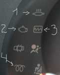
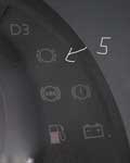
|
Aleksey |
Заголовок сообщения:
|
|
|
3 — кардиограмма, вроде как неисправность системы управления двигателем _________________ |
| Вернуться к началу |
|
|
КомБат |
Заголовок сообщения:
|
|
|
Ромашка, когда включашь зажигание, нужно подождать пока потухнет лампочка-4 потом заводить _________________ |
| Вернуться к началу |
|
|
Ромашка |
Заголовок сообщения:
|
|
|
КомБат писал(а): Ромашка, когда включашь зажигание, нужно подождать пока потухнет лампочка-4 потом заводить «буду ждать» |
| Вернуться к началу |
|
|
Emelya |
Заголовок сообщения:
|
|
|
Ромашка 1- лампа перегрева катализатора, 2 — контр лампа предпусковаго подогревателя диз. двигателя. |
| Вернуться к началу |
|
|
Ромашка |
Заголовок сообщения:
|
|
|
Emelya писал(а): Ромашка 1- лампа перегрева катализатора, 2 — контр лампа предпусковаго подогревателя диз. двигателя. Спасибо |
| Вернуться к началу |
|
|
Picasso |
Заголовок сообщения:
|
|
|
Помогите советом! При включении зажигания загорается лампа 3, лампа «подушка» (что под ней), ремешок (еще ниже), 5, батарейка и масленка (на фото нет). После 4-6 секунд остается гореть только ремешок, батарейка и масленка. Вопрос: это нормально если загорается «кардиограмма»? |
| Вернуться к началу |
|
|
Ortin |
Заголовок сообщения:
|
||
|
Да, нормально. На короткое время лампы загораются чтобы проверить их работоспособность. Если загорятся потом — значит соотв. проблемы. _________________ |
||
| Вернуться к началу |
|
||
Часовой пояс: UTC + 2 часа [ Летнее время ]
Кто сейчас на конференции |
|
Зарегистрированные пользователи: Bing [Bot], Yandex [Bot] |
| Вы не можете начинать темы Вы не можете отвечать на сообщения Вы не можете редактировать свои сообщения Вы не можете удалять свои сообщения Вы не можете добавлять вложения |
Обновлено: 05.06.2023
Бортовой компьютер — информационная система, которая оценивает состояние электронных систем автомобиля и выводит результаты диагностики, а также информацию о поездке на экран приборной панели.
Когда в управляющей электронике возникают сбои, владелец видит соответствующее предупреждение на приборной панели.
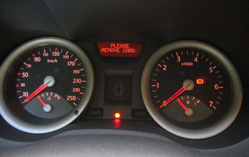
В случаях, когда вы поняли причину неисправности и приняли меры, а ошибка не пропадает, полезно обнулить показатели борткомпьютера Renault. Для этого нужно нажать и удерживать клавишу.
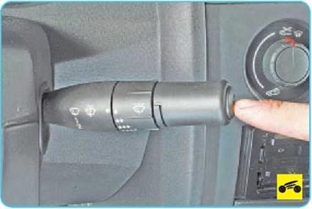
На дисплее бортового компьютера Renault обычно отображаются два числовых значения в километрах — это показатели счетчиков пробега, суммарного (А) и суточного (Б).
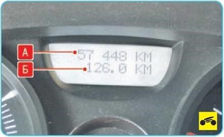
- INSERER LA CARTE — вставьте ключ-карту в считывающее устройство.
- NIVEAU HUILE CORRECT — уровень масла в норме.
- ECLAIRAGE AUTO DES FEUXOFF- автоматическое включение световых приборов выключено.
- ESP/ASR DESACTIVE — отключение системы стабилизации и противобуксовочной системы.
- CAPTEURS PNEUS ABSENT — датчик давления воздуха в шинах отсутствует или неисправен.
- PRESSION PNEUS A REAJUSTER — приведите в норму давление воздуха в шинах.
- FILTRE GAZOLE A PURGER — проверьте состояние фильтра дизельного двигателя.
- BOITE VITESSES A CONTROLER — проверьтекоробку передач.
- CARTE NON DETECTEE — ключ-карта не распознан.
- PILE CARTE A CHANGER — замените батарейку в ключе-карте.
- PANNE DE L INJETION — неисправна система впрыска.
- CREVAISON CHANGER ROUE — прокол колеса, замените колесо.
- SURCHAUFFE DU MOTEUR — перегрев двигателя.
- PANNE DE LA DIRECTION — неисправность рулевого управления.
- DEFAILLANCE ELECTRONIQUE — неисправность электронных систем автомобиля.
О том, как самостоятельно проверить катушки зажигания своего Рено, мы писали здесь.
Перед третьей генерацией Клио стояла задача оказаться не хуже второго, а создатели сосредоточились на улучшении уже существующего. Поэтому Clio III выглядит как модернизированный Clio II: тот же компактный и изящный кузов без новаторских дизайнерских решений.
Серьезно изменился облик модели в ходе рестайлинга 2009 года.
Внутри же ничего особо не изменилось, разве что табло бортового компьютера сменил ЖК-дисплей с навигацией.
Французский хэтчбек остался комфортным и маневренным, с хорошей плавностью хода и нормальной управляемостью. Выпускали Renault Clio III до 2012 года, когда на смену ему пришло уже четвертое поколение.
Кузов и электроника
Еще из характерных черт — округлая крыша, плавные линии боковин и короткие свесы кузова.
Критику владельцев вызывает несуразно длинная ручка АКП и отсутствие подсветки передач ночью. А еще рулевая колонка в не топовых комплектациях регулируется только по углу наклона.
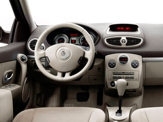
Кузов Clio III отличается коррозийной стойкостью. Передние крылья хэтчбека вообще выполнены из пластика, все, что им грозит — трещины.
Если вам встретилась коррозия, скорее всего, речь идет о непрофессиональном ремонте поврежденного в ДТП автомобиля.
А вот запаска расположена неудобно: снаружи под полом багажника. Типичной проблемой считаестя шум, который издает дверь багажника. Регулировка крышки помогает ненадолго.
Что касается компонентов электрики и электроники, это регулярная головная боль владельцев.
Встречаются отказы ключ-карты и переключателей на руле. Глючит блок управления панелью приборов, электроподъемники и электродвигатель стеклоочистителей. Система кондиционирования сбоит из-за нестабильной работы управляющей электроники.
Двигатели и трансмиссия
В гамме двигателей Renault Clio III — три бензиновых мотора в разных вариантах форсировки, а также несколько популярных турбодизельных вариантов.
- В первые годы выпуска покупателям предлагались варианты бензиновых 1, 2 л (65 и 75 л.с.), 1,6 л (88 и 112 л.с.) и турбодизельный 1.5 dCi (68, 86 и 106 л.с.).
- Затем в гамму добавились 1,2 л (78 л.с.), 2,0 л (139 л.с.) инжекторы и турбодизельный 1.5 dCi (103 л.с.).
- В 2007 году создатели предложили бензиновый турбированный 1,2 л TСe (100 л.с.).
- После рестайлинга 2009 года в гамму добавился 1,6-литровый (128 л.с.) бензиновый двигатель, а позднее — и популярный турбодизель 1.5 dCi (75 и 88 л.с.).
- В 2011 линейка двигателей пополнилась бензиновыми 1,6-литровыми моторами: атмосферным (100 л.с.) и TCe (112 л.с)
1,2-литровый 75-сильный считается беспроблемным по части обслуживания, но владельцы не рады такой динамике. Ехать в городском потоке его мощности хватит. Совершать обгоны и карабкаться на уклон — нет. В то же время этот двигатель считается непроблемным, потребляет мало топлива.
1,4-литровый инжектор с его 98 л.с. выглядит предпочтительнее, особенно в режиме высоких оборотов. Разгон остается размеренным.
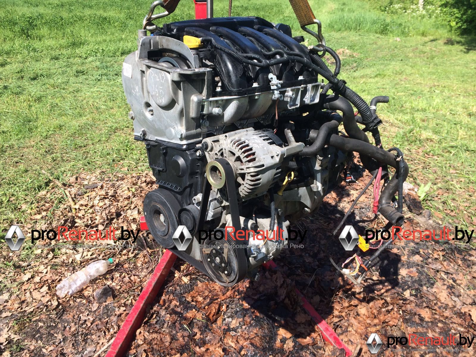
Из типичных проблем четырехклапанных инжекторов (1,4 л и 1,6 л) — катушки зажигания. Еще владельцы сталкиваются с ремонтом дроссельной заслонки и заменой подушек двигателя. Но в целом, это достаточно надежные варианты.
1,2-литровый турбированный мотор привередлив в обслуживании и способен обернуться высокими затратами на ремонт. Из плюсов — хорошая тяга при относительно скромном топливном расходе.
2,0-литровый атмфосферный двигатель всерьез рассматривают только любители объемных ДВС — расходы на его содержание и обслуживание высоки.
Турбодизели, как и всегда в случае с подержанными авто с большим пробегом — кот в мешке. Тяговитость и экономия на расходе топлива — то, то хвалят владельцы.
Про популярный в Беларуси 1,5-литровый турбодизель К9К мы подробно писали здесь.
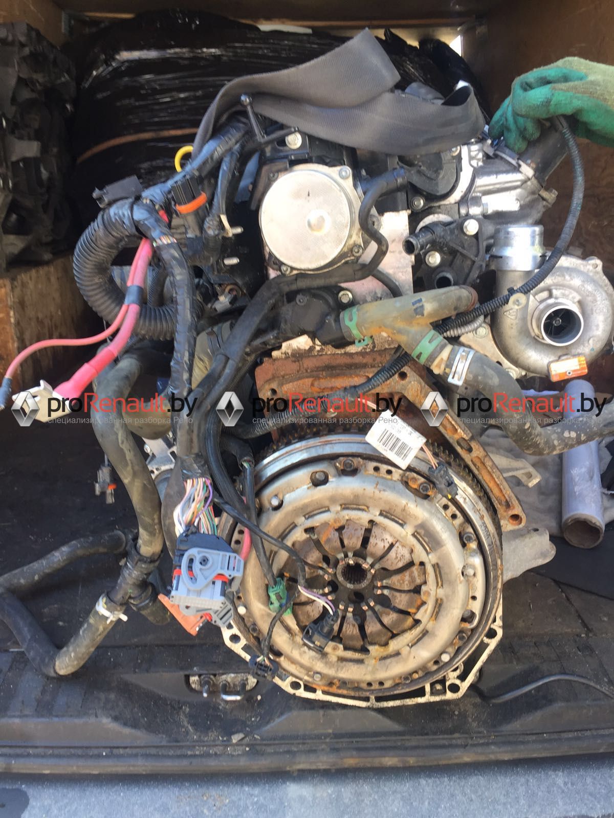
Ходовая часть и рулевое управление
За что владельцы хвалят Клио, так это за мягкую комфортную подвеску, которая отлично отрабатывает и ямки на дороге, и трамвайные пути. И при этом крены в поворотах очень умеренные. И все благодаря высоким пружинам и мягким амортизаторам.
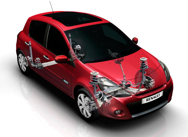
За комфорт, правда, приходится платить ресурсом компонентов подвески.
Первыми сдаются опорные подшипники передних стоек, сайлент-блоки передних рычагов и стойки стабилизатора. Ступичные подшипники также не слишком долговечны. Замена деталей не доставляет особых проблем, но задние подшипники меняются в сборе.
Итого
К достоинствам модели относят просторный кузов с хорошей коррозийной стойкостью, хорошую плавность хода, безопасность. К минусам — недостаточную динамику и проблемы с электрооборудованием. Многие называют стоимость хэтчбека завышенной.
Надежность модели средняя, но по сравнению со вторым Клио, третий стал комфортней и практичнее.
Чтобы не ошибиться в выборе двигателя в Renault Clio III, лучше остановиться на бензиновом 1,4 — или 1,6-литровом агрегате. На свой риск, можно выбрать турбированный 1,2-литровый инжектор. С турбодизелями стоит быть осторожнее, если нет предыдущей истории обслуживания.

В случае замены щитка приборов, его
конфигурирование осуществляется автоматически
при вк лючении зажигания. Центральный
электронный коммутационный блок салона
(ЦЭКБС) пересылает в щиток приборов
конфигурацию прежнего щитка приборов.
В случае, если программирование щитка приборов
не было произведено по какой-либо причине, то в
память ЦЭКБ будет занесена неисправность
«Щиток прибор не сконфигурирован».
Для изменения конфигурации щитка приборов
выполните процедуру с помощью диагностического
прибора:
Проверьте состояние мультиплексной сети, а
затем выйдите из режима диагностики,
Отсоедините аккумуляторную батарею (не менее
чем на одну минуту), затем подключите ее вновь,
НЕ ВКЛЮЧАЯ ЗАЖИГАНИЯ, повторите проверку
мультиплексной сети (не обращайте внимания
на неисправные сегменты вызванные
выключением зажигания
Войдите в режим диалога с ЦЭКБС,
В меню «Команды», «Специальные команды»,
подтвердите строку «CF 719 Тип щитка
приборов»
означает выход из режима,
На дисплее прибора высвечивается:
Выключите зажигание, затем подтвердите это,
Часы «с или без»,
Информация о скорости движения «АБС или
датчик КП»
Тип двигателя «бензиновый или дизельный»,
Система питания сжиженным газом «с или без»
Система стабилизации траектории «с или без»
После этого на дисплее прибора отображается:
«Правильно ли выполнено
конфигурирование?»
При ошибочном вводе подтвердите «НЕТ», чтобы
повторить процедуру.
Если ответ «ДА», дважды выключите и включите
зажигание, чтобы подтвердить произведенное
конфигурирование щитка приборов.
На дисплее прибора высвечивается:
«Конфигурирование закончено».


Примечание:
— При нормальной эксплуатации уровень масла замеряется после выключения зажигания более, чем на одну минуту. В остальных случаях указывается старый уровень масла.
— В норме регистрируемый уровень масла не остается постоянным даже при коротких плечах пробега (например, парковка на уклоне, задержка слива масла после останова двигателя, особенно холодного и т.п.)
2. Одометр.
Общий пробег автомобиля выводится на дисплей после указания уровня масла. Время вывода составляет 30 секунд. Нажатие на кнопки ADAC или RESET уменьшает время индикации общего пробега. Частичный пробег вместо общего выводится после краткого нажатия кнопки ADAC установка нупя счетчика частичного пробега проводится нажатием кнопки RESET.
Примечание: Пробег может выводится в километрах или милях, в зависимости от версии.
3. Бортовой компьютер (ADAC)
После вывода информации об общем пробеге автомобиля на дисплей может быть выведена информация об эксплуатационных параметрах автомобиля. Вывод информации осуществляется повторными нажатиями на кнопку ADAC (расположена на торце рычага выключателя очистителя):
— полный расход топлива (в литрах на 100 км или миль на галлон).

— средний расход топлива с момента последнего обнуления (в литрах на 100 км или миль на галлон).

Средний расход выводится только после того, как автомобиль проехал не менее 400 метров. Подсчитывается как частное от деления общего расхода на пройденный путь.
— текущий расход топлива (в литрах на 100 км или миль на галлон).

Текущий расход регистрируется при скорости выше 30 км/час. При отпущенной педали акселератора и скорости выше 30 км/час текущий расход топлива принимается равным нулю.
Примечание: Данная опция не применяется дпя автомобилей, поставляемых в Великобританию.
— пробег до выработки топлива (в километрах или милях) при данном режиме движения автомобиля.

Примечание: Данная опция отключается при горящем индикаторе низкий уровень топлива».
— пробег после последнего обнуления одометра.

— средняя скорость движения с момента последнего обнуления.

Средняя скорость определяется как частное от деления пройденного пули на время движения. Таймер встроен в бортовой компьютер.
Поиск неисправностей в системе бортового компьютера
Для проведения поиска неисправностей включите зажигание (двигатель не запускать) и удерживайте в нажатом положении кнопку ADAC. Должны загореться все индикаторы стрелки четырех указателей передвинуться на один шаг. На дисплее появится тестовая картинка — все сегменты должны гореть.


Если выводится буква t, то имеет место неверный сигнал подачи топлива долее четырех секунд. Если выводится буква J, имеется неисправность в цепи указатепя уровня топлива (обрыв цепи долее 100 секунд). Сопротивление датчика должно лежать в пределах 5 — 350 Ом. Если выводится буква d. то имеет место постоянно неверный сигнал подачи топлива. Если выводится буква h, то имеет место неисправность в цепи датчика уровня масла. Сопротивление датчика должно лежать в пределах 6 — 20 Ом. Если выводятся прочерки, неисправностей не обнаружено. Для прекращения диагностики нажмите кнопку RESET.
Примечание: Диагностика систем автомобиля бортовым компьютером не проводится.
Читайте также:
- Etacs decoder mitsubishi аналоги
- Дтп кто чаще попадает в дтп мужчины или женщины
- Неисправности сцепления газ 3110 двигатель 406 инжектор
- Адаптация робот форд куга
- Потерял ключи от ниссан примера

Jaune
1.53
Tableau de bord : témoins lumineux (B85 — C85 — S85 — Renault)
ЩИТОК ПРИБОРОВ: сигнальные лампы
(продолжение)
Î
Сигнальная лампа системы
поддержания/ограничения
скорости
Работа этой лампы описана в разделе
«Система поддержания/ограничения ско-
рости» в главе 2.
©
Сигнальная лампа необходи-
мости проведения обслуживания
Лампа загорается при включении зажига-
ния и гаснет через несколько секунд.
Может включаться одновременно с дру-
гими сигнальными лампами или сообще-
ниями на щитке приборов.
Если она загорается при движении, обра-
титесь на ближайшую сервисную станцию
компании-производителя.
®
Сигнальная лампа экстренной
остановки
Лампа загорается при включении зажига-
ния и гаснет через несколько секунд.
Включается одновременно с другими сиг-
нальными лампами и/или с появлением
сообщений на щитке приборов и звуко-
вым сигналом.
Необходимо остановиться, как только по-
зволят условия движения. Обратитесь на
сервисную станцию компании-производи-
теля.
2
Сигнальная лампа незакры-
той(-ых) двери(-ей)
Ô
Сигнальная лампа темпера-
туры охлаждающей жидкости
Лампа загорается при включении зажига-
ния и гаснет через несколько секунд.
– Если лампа мигает, это свидетель-
ствует о неисправности в системе
впрыска. Остановитесь и обратитесь
на сервисную станцию компании-про-
изводителя.
– Если лампа горит постоянно, останови-
тесь и дайте двигателю поработать на
холостом ходу одну или две минуты.
Температура должна понизиться, и сиг-
нальная лампа погаснет. Если этого не
произошло, остановите двигатель. Дайте
двигателю остыть и проверьте уровень
охлаждающей жидкости.
Обратитесь на сервисную станцию ком-
пании-производителя.
A
Наличие и функционирование сигнальных ламп ЗАВИСИТ ОТ КОМПЛЕКТАЦИИ АВТОМОБИЛЯ И СТРАНЫ ПОСТАВКИ.

1.54
Tableau de bord : témoins lumineux (B85 — C85 — S85 — Renault)
Jaune
ЩИТОК ПРИБОРОВ: сигнальные лампы
(продолжение)
Æ
Сигнальная лампа серьезной
неисправности системы впры-
ска
Лампа загорается при включении зажига-
ния и гаснет через несколько секунд.
Если лампа загорается во время движения
автомобиля, это свидетельствует о неис-
правности системы впрыска. Немедленно
остановитесь, выключите зажигание и об-
ратитесь на сервисную станцию компа-
нии-производителя.
Ò
Сигнальная лампа неисправ-
ности электронных систем ав-
томобиля или наличия воды в топлив-
ном фильтре дизельного двигателя
Лампа загорается при включении зажига-
ния и гаснет через несколько секунд.
Если лампа горит во время движения, это
может указывать на неисправность ЭБУ
системы впрыска или автоматической ко-
робки передач или на наличие воды в ди-
зельном топливе. Срочно обратитесь на
сервисную станцию компании-производи-
теля.
ù
Сигнальная лампа системы
поддержания курсовой устой-
чивости (ESP) и антипробуксовочной
системы (ASR).
Лампа загорается при включении зажига-
ния и гаснет через несколько секунд.
Загорание сигнальной лампы может
быть вызвано несколькими причи-
нами, см. разделы «Система поддер-
жания курсовой устойчивости (ESP)» и
«Антипробуксовочная система (ASR)» в
главе 2.
À
Сигнальная лампа падения
давления масла в двигателе
Лампа загорается при включении зажига-
ния и гаснет через несколько секунд.
Если эта лампа загорается во время
движения одновременно с сигнальной
лампой
®
и раздается звуковой
сигнал, немедленно остановитесь и вы-
ключите зажигание.
Проверьте уровень масла. Если уровень
в норме, причина загорания лампы иная.
Обратитесь на сервисную станцию ком-
пании-производителя.
U
Сигнальная лампа адаптив-
ного усилителя рулевого
управления
Лампа загорается при включении зажига-
ния и гаснет через несколько секунд.
Если сигнальная лампа загорается во
время движения, это указывает на не-
исправность системы, обратитесь как
можно быстрее на сервисную станцию
компании-производителя.
Наличие и функционирование сигнальных ламп ЗАВИСИТ ОТ КОМПЛЕКТАЦИИ АВТОМОБИЛЯ И СТРАНЫ ПОСТАВКИ.
A

Jaune
1.55
Tableau de bord : témoins lumineux (B85 — C85 — S85 — Renault)
ЩИТОК ПРИБОРОВ: сигнальные лампы
(продолжение)
Наличие и функционирование сигнальных ламп ЗАВИСИТ ОТ КОМПЛЕКТАЦИИ АВТОМОБИЛЯ И СТРАНЫ ПОСТАВКИ.
É
Сигнальная лампа предпуско-
вого подогрева (на автомоби-
лях с дизельным двигателем)
Данная сигнальная лампа загорается при
включении зажигания. Она показывает,
что свечи предпускового подогрева рабо-
тают.
Она гаснет, когда предварительный подо-
грев осуществлен. Двигатель может быть
запущен.
Ü
Сигнальная лампа противоса-
жевого фильтра
См. раздел «Особенности автомобилей с
дизельным двигателем, оснащенных про-
тивосажевым фильтром» в главе 2.
Ú
Сигнальная лампа заряда ак-
кумуляторной батареи
Лампа загорается при включении зажига-
ния и гаснет через несколько секунд.
Если она загорается во время движе-
ния одновременно с сигнальной лампой
®
и раздается звуковой сигнал, это
свидетельствует о повышенном или пони-
женном токе заряда.
Остановитесь и обратитесь на сервисную
станцию компании-производителя.
Ä
Сигнальная лампа системы
снижения токсичности
На автомобилях, оборудованных этой си-
стемой, сигнальная лампа загорается при
запуске двигателя, после чего гаснет.
– Если лампа горит постоянно, срочно
обратитесь на сервисную станцию
компании-производителя.
– Если лампа мигает, снижайте частоту
вращения коленчатого вала двигателя,
пока мигание не прекратится. Срочно
обратитесь на сервисную станцию
компании-производителя.
См. раздел «Рекомендации по уменьше-
нию токсичности отработавших газов, эко-
номии топлива и вождению» в главе 2.
D
Сигнальная лампа включения
стояночного тормоза и сиг-
нальная лампа неисправности тормоз-
ной системы
Загорается при включении зажигания и
гаснет после выключения стояночного
тормоза.
Если лампа загорается при торможе-
нии одновременно с сигнальной лампой
®
и раздается звуковой сигнал, это
указывает на низкий уровень тормозной
жидкости или на неисправность тормоз-
ной системы.
Остановитесь и обратитесь на сервисную
станцию компании-производителя.
è
Сигнальные лампы, связан-
ные с работой автоматиче-
ской коробки передач
См. разделы «Автоматическая
коробка передач» и «Коробка
передач Quickshift» в главе 2.
c
A
ê
A

indicateurs :
1.56
Tableau de bord : afficheurs et indicateurs (B85 — C85 — S85 — Renault)
Jaune
ЩИТОК ПРИБОРОВ: дисплеи и индикаторы
Тахометр 1
(единица деления шкалы —
1000 об/мин)
Указатель температуры охлаждающей
жидкости 2
В обычных условиях эксплуатации
стрелка указателя не должна доходить до
зоны A. В сложных условиях эксплуата-
ции стрелка может переходить в эту зону.
Тревогу должно вызывать только включе-
ние сигнальной лампы
®
одновре-
менно с появлением сообщения на щитке
приборов и звуковым сигналом.
Указатель температуры охлаждающей
жидкости 3
Тревогу должно вызывать только включе-
ние сигнальной лампы
Ö
и
®
од-
новременно с появлением сообщения на
щитке приборов и звуковым сигналом.
Указатель уровня топлива 4
1
1
A
3
4
2
4

Безопасность детей: установка детского сиденья………………………………………………………………………………………….. 2
Регулировка света фар………………………………………………………………………………………………………………………………… 5
Многофункциональный дисплей………………………………………………………………………………………………………………….. 6
Система поддержания курсовой устойчивости (ESP)…………………………………………………………………………………… 11
Антипробуксовочная система (ASR)…………………………………………………………………………………………………………….. 13
Уровень масла в двигателе…………………………………………………………………………………………………………………………. 15
Набор инструментов…………………………………………………………………………………………………………………………………… 16
Средства для ремонта шин в аэрозольной упаковке……………………………………………………………………………………. 17
Замена колеса……………………………………………………………………………………………………………………………………………. 18
Шины………………………………………………………………………………………………………………………………………………………… 19
Задние фонари: замена ламп……………………………………………………………………………………………………………………… 22
Идентификационная табличка……………………………………………………………………………………………………………………. 25
Габаритные размеры …………………………………………………………………………………………………………………………………. 26
Характеристики двигателя…………………………………………………………………………………………………………………………. 27
Массовые характеристики………………………………………………………………………………………………………………………….. 28
Сигнальная лампа необходимости выбора другой передачи
Включение данной сигнальной лампы на щитке приборов, сопровождаемое звуковым сигналом, указывает на необхо
димость перейти на передачу выше.
Информация, содержащаяся в данном документе, отменяет и/или дополняет информацию, представленную в основном руководстве.
- Главная
- Секреты
- Самая полная расшифровка сообщений бортового компьютера Renault
Дата публикации 19 октября 2018. Опубликовано в Секреты Рено
Бортовой компьютер — информационная система, которая оценивает состояние электронных систем автомобиля и выводит результаты диагностики, а также информацию о поездке на экран приборной панели.
Когда в управляющей электронике возникают сбои, владелец видит соответствующее предупреждение на приборной панели.
Поэтому важно понимать, что именно сообщает вам ваш «Рено». Для решения некоторых проблем понадобится компьютерная диагностика с использованием специального ПО. Отдельные ситуации решаются только после технического обслуживания и даже ремонта машины.
В случаях, когда вы поняли причину неисправности и приняли меры, а ошибка не пропадает, полезно обнулить показатели борткомпьютера Renault. Для этого нужно нажать и удерживать клавишу.
Информационные сообщения бортового компьютера «Рено»
На дисплее бортового компьютера Renault обычно отображаются два числовых значения в километрах — это показатели счетчиков пробега, суммарного (А) и суточного (Б).
Также на дисплее БК вашего «Рено» может отображаться:
- CARBURANT — объем израсходованного с момента обнуления показателей топлива
- MOYNNE — средний расход топлива (после обнуления)
- INSTANTANNE — текущий расход топлива, отображается на скорости больше 30 км/ч
- AUTONOMIE — на сколько хватит топлива в баке, рассчитывается с учетом среднего расхода с момента обнуления, выводится после 400 м пути
- DISTANCE — пройденный путь (с момента последнего обнуления)
- MOYENNE — средняя скорость, отображается после первых 400 м пути
- VIDANGE DANS — оставшийся до планового ТО пробег. Сбрасывать этот показатель лучше только после замены масла, проведения ТО.
- REGULATEUR, LIMITEUR — заданное значение скорости системы круиз-контроль.
- PAS DE MESSAGE MEMORISE — бортовой журнал, выводятся информационные сообщения.
Расшифровка сообщений БК Renault с французского
- INSERER LA CARTE — вставьте ключ-карту в считывающее устройство.
- NIVEAU HUILE CORRECT — уровень масла в норме.
- ECLAIRAGE AUTO DES FEUXOFF — автоматическое включение световых приборов выключено.
- ESP/ASR DESACTIVE — отключение системы стабилизации и противобуксовочной системы.
- CAPTEURS PNEUS ABSENT — датчик давления воздуха в шинах отсутствует или неисправен.
- PRESSION PNEUS A REAJUSTER — приведите в норму давление воздуха в шинах.
- FILTRE GAZOLE A PURGER — проверьте состояние фильтра дизельного двигателя.
- BOITE VITESSES A CONTROLER — проверьтекоробку передач.
- CARTE NON DETECTEE — ключ-карта не распознан.
- PILE CARTE A CHANGER — замените батарейку в ключе-карте.
- PANNE DE L INJETION — неисправна система впрыска.
- CREVAISON CHANGER ROUE — прокол колеса, замените колесо.
- SURCHAUFFE DU MOTEUR — перегрев двигателя.
- PANNE DE LA DIRECTION — неисправность рулевого управления.
- DEFAILLANCE ELECTRONIQUE — неисправность электронных систем автомобиля.
Расшифровка сообщений БК Renault с английского + пояснения
- Automatic lighting OFF / out oorder (fault) — система автовключения наружного освещения (датчик света) выключена / неисправна
- Automatic wipers OFF/ out oorder (fault) — режим автовключения стеклоочистителей (датчик дождя) выключена / неисправна
- Adjust oil level — долейте до необходимого уровня моторное масло
- Adjust tyre pressure — отрегулируйте давление воздуха в шинах
- Boot open — открыт багажник
- Breaking fault / break fault — неисправность тормозной системы (упал уровень тормозной жидкости, изношены колодки и т.п.)
- Card not detected — карточка не обнаружена
- Card reader not working / Electronic fault (поочередно) — считывающее карту устройство вышло из строя / электронные системы вышли из строя
- Change card battery / replace card battery — замените батарейку в карте (после замены нажать одновременно все кнопки на карте, чтобы стереть ошибку)
- Change oil soon — напоминание о том, что вскоре нужно заменить моторное масло
- Check ABS — проверьте систему ABS (сопровождается лампой Service, зимой, когда снег набивается в тормозную систему, помогает многократный выжим педали тормоза и перезапуск мотора)
- Check airbag— проверьте подушки безопасности (стоит проверить контакты в разъеме под сиденьем, шлейф в подрулевом переключателе)
- Check diesel filter — проверьте топливный фильтр
- Check door loсks — проверьте блокировку дверей (появляется обычно когда водитель ставит блокировку, а пассажир дергает ручку открывания двери; устраняется включением-выключением блокировки кнопкой на двери водителя)
- Check emissions— проверьте систему выхлопа (нейтрализатор ОГ, лямбда-зонд)
- Check gearbox — проверьте автоматическую коробку передач
- Check injection — проверьте систему впрыска (возможно, грязный дроссель или его разъем, сопровождается плавающими оборотами в РХХ)
- Check steering — проверьте рулевое управление (рейку, электроусилитель, ходовую часть)
- Confirm engine stop / press stop twice (поочередно)- подтвердите остановку мотора / нажмите кнопку «стоп» дважды
- Cruise control — включен регулятор скорости (круиз-контроль)
- Cruise control not working — система круиз-контроля неисправна
- Depress the brake / Declutch + «start» — выжмите педаль тормоза / сцепления и запустите двигатель с кнопки (поочередно)
- Door open — дверь открыта
- Electronic failure / electronic fault — неисправность (ошибка) управляющей электроники (в основном возникает при проблемах с педалью тормоза, когда не горят стоп-сигналы)
- Engine overheating — перегрев двигателя (остановитесь, заглушите мотор, примите меры)
- ESP disconnected / out of order — система стабилизации кузова отключена / вышла из строя
- Faulty engine immobilizer — система электронной противоугонной блокировки запуска мотора неисправна
- Faulty injection — система впрыска неисправна
- Faulty steering — рулевое управление неисправно
- Gearbox overheating — коробка передач перегревается
- Gear shift in P or N / press on brake + «start» — переведите АКП в режим P или N / выжмите педаль тормоза и нажмите кнопку запуска мотора (поочередно)
- Hands-free out of order — система «свободные руки» не функционирует
- Heated seat ON — обогрев сиденья включен
- Low battery — низкий уровень заряда АКБ (сочетается с сигналом Stop и значком АКБ после запуска двигателя; требует замены реле регулятора напряжения в генераторе или генератора)
Luggage compartment open — открыта задняя дверь - Min IooooooL / Min I_ _ _ L — уровень масла максимальный / минимальный
- No message stored/available — в памяти БК нет сообщений о неисправностях (все хорошо)
- Oil level ok / correct — уровень масла в двигателе нормальный
- Please insert/ remove card — вставьте / извлеките карту
- Press cluth + start — выжмите педаль сцепления, запустите двигатель с кнопки (выводится при попытке запуска двигателя с включенной передачей на МКП или нажатой педалью тормоза на АКП)
- Press the brake pedal — нажмите на педаль тормоза
Puncture: change the wheel / tyre puncture — шина проколота, замените колесо - Regenerate particle filter — требуется замена воздушного салонного фильтра
- Restricted card mode — включен резервный режим карты
- Service due soon / now — предупреждение о необходимости ТО скоро / сейчас (Чтобы сбросить пробег, нужно завести двигатель, дождаться появления этой надписи, нажать кнопку БК и ждать, пока цифры пробега не «добегут» до 15000, затем отпустить кнопку)
- Shift into neutral — установите рычаг КП в нейтральное положение
- Speed limiter out of order — неисправен ограничитель скорости
- Steering locked — рулевое управление заблокировано (низкий уровень напряжения в бортвети или двигатель заглушили при вывернутых до упора колесах). Если такое сообщение появляется на экране БК, а следом Breaking Fault — есть проблемы с запуском двигателя (стартер и т.п.).
- Steering not locked — рулевое управление не заблокировано
- Top—Up Oil level — долейте масло по уровню
- Turn steering-wheel + start — покрутите руль одновременно нажав на запуск двигателя с кнопки (выжав педаль сцепления или тормоза), чтобы разблокировать руль.
- Tyre pressure sensor not working / fault — датчик системы контроля давления в шинах неисправен
- Underinflation: slow down — давление в шинах упало, снижайте скорость.
О том, как самостоятельно проверить катушки зажигания своего Рено, мы писали здесь.