
-
Contents
-
Table of Contents
-
Bookmarks
Quick Links
ECODRIVE03/DURADRIVE
Drive for General Automation
with SERCOS and Parallel Interface
Troubleshooting Guide: SGP 03VRS
SYSTEM200
DOK-ECODR3-SGP-03VRS**-WA01-EN-P
Related Manuals for REXROTH ECODRIVE03
Summary of Contents for REXROTH ECODRIVE03
-
Page 1
ECODRIVE03/DURADRIVE Drive for General Automation with SERCOS and Parallel Interface Troubleshooting Guide: SGP 03VRS SYSTEM200 DOK-ECODR3-SGP-03VRS**-WA01-EN-P… -
Page 2
Date DOK-ECODR3-SGP-03VRS**-WA01-EN-P 08.2002 First edition 2002 Rexroth Indramat GmbH Copyright Copying this document, giving it to others and the use or communication of the contents thereof without express authority, are forbidden. Offenders are liable for the payment of damages. All rights are reserved in the event of the grant of a patent or the registration of a utility model or design (DIN 34-1). -
Page 3
ECODR3-SGP-03VRS About this Documentation Summary of Documentation – Overview Functional Description: Description of all implemented Function based on SERCOS-Parameters Order designation: DOK-ECODR3-SGP-03VRS**-FK01-EN-P 2 8 2 8 0 1 Parameter Description: A description of all parameters used in the firmware Order designation: DOK- ECODR3—SGP-03VRS**-PA01-EN-P 2 8 2 8 0 1 Troubleshooting Guide:… -
Page 4
About this Documentation ECODR3-SGP-03VRS Notes DOK-ECODR3-SGP-03VRS**-WA01-EN-P… -
Page 5: Table Of Contents
ECODRIVE03-SGP-03VRS Contents Contents Diagnostic Message Descriptions Overview of the Diagnostic Message Descriptions……………. 1-1 Diagnostic Message Types…………………. 1-1 Construction of a Diagnostic Message ………………1-1 H1-Display……………………..1-2 Important directions for use Appropriate use……………………..2-1 Introduction ……………………..2-1 Areas of use and application………………..2-2 Inappropriate use ………………………
-
Page 6
Contents ECODRIVE03-SGP-03VRS F224 Maximum braking time exceeded………………. 4-6 F226 Undervoltage in power section ………………4-6 F228 Excessive deviation ………………….4-6 F229 Encoder 1 failure: quadrant error………………4-7 F230 Max. signal frequency of encoder 1 exceeded…………… 4-7 F236 Excessive position feedback difference…………….4-8 F237 Excessive position command difference ……………. -
Page 7
ECODRIVE03-SGP-03VRS Contents F878 Velocity loop error………………….4-25 F879 Velocity limit S-0-0091 exceeded …………….. 4-26 Warning Diagnostic Messages E… ………………… 4-27 E217 Cooling fan too slow ………………… 4-28 E221 Warning Motor temp. surveillance defective …………..4-28 E225 Motor overload………………….4-28 E226 Undervoltage in power section ………………4-29 E247 Interpolation velocity = 0……………….. -
Page 8
Contents ECODRIVE03-SGP-03VRS Description of Diagnostic Messages B…; C…, D… and A Command Diagnostic Messages B…, C… and D……………..5-1 B100 Command Release motor holding brake……………. 5-2 B101 Command not enabled ………………..5-2 B200 Brake check command………………..5-2 B201 Brake check only with drive enable …………….5-2 B202 Error during abrasion of the brake……………… -
Page 9
ECODRIVE03-SGP-03VRS Contents C236 Feedback 1 required (P-0-0074) ……………… 5-16 C238 Wrong function of encoder 2 (->S-0-0022) …………..5-16 C241 Binary encoder resolution necessary …………….5-16 C300 Command Set absolute measuring…………….5-16 C302 Absolute measuring system not installed…………..5-16 C400 Switching to parameter mode ………………5-17 C401 Drive active, switching not allowed ……………. -
Page 10
Contents ECODRIVE03-SGP-03VRS D903 Inertia detection failed ………………..5-27 D904 Gain adjustment failed………………..5-27 D905 Travel range invalid, P-0-0166 & P-0-0167…………..5-28 D906 Travel range exceeded………………..5-28 Status diagnostic messages ………………….5-29 A000 Communication phase 0………………..5-29 A001 Communication phase 1………………..5-29 A002 Communication phase 2……………….. -
Page 11
ECODRIVE03-SGP-03VRS Contents A210 Process block mode, encoder 2 ………………. 5-39 A211 Process block mode lagless, encoder 2…………… 5-39 A218 JOG mode negative…………………. 5-40 A400 Automatic drive check and adjustment…………….. 5-40 A401 Drive deceleration to standstill ………………5-40 A800 Unknown operating mode ……………….. 5-40 Diagnostic Messages for Basic Initialization and After Fatal System Errors ……. -
Page 12
VIII Contents ECODRIVE03-SGP-03VRS Index Service & Support Helpdesk ……………………….7-1 Service-Hotline……………………..7-1 Internet ……………………….7-1 Vor der Kontaktaufnahme… — Before contacting us…………… 7-1 Kundenbetreuungsstellen — Sales & Service Facilities …………..7-2 DOK-ECODR3-SGP-03VRS**-WA01-EN-P… -
Page 13: Diagnostic Message Descriptions
ECODRIVE03-SGP-03VRS Diagnostic Message Descriptions Diagnostic Message Descriptions Overview of the Diagnostic Message Descriptions Diagnostic Message Types Each operational state of the drive will be characterized with a diagnostic message. Differentiations will be made between: • Error diagnostic messages • Warning diagnostic messages •…
-
Page 14: H1-Display
Diagnostic Message Descriptions ECODRIVE03-SGP-03VRS H1-Display The H1-Display serves as an optical display of the diagnostic message on the drive. H1-Display FA5047f1.fh7 Fig. 1-2: H1-Display The diagnostic number appears on this two-positional seven-segment display. The image can be seen on the figure «Priority-dependent diagnostic message display»…
-
Page 15
ECODRIVE03-SGP-03VRS Diagnostic Message Descriptions If more than one diagnostic message is waiting, then the message with Diagnostic Message Output the highest priority will be displayed. Priority The following graphic classifies operation status in order of importance. error warning command error… -
Page 16
Diagnostic Message Descriptions ECODRIVE03-SGP-03VRS Clear Coded Diagnostic Message The clear coded diagnostic message contains the diagnostic message number followed by the diagnostic text, as shown in the example «Excessive deviation» (Fig. 1-1). It can be read out with parameter S-0-0095, Diagnostic message and directly displays the operation status on an operator surface. -
Page 17: Important Directions For Use
The user alone carries all responsibility of the risks. Before using Rexroth Indramat products, make sure that all the pre- requisites for appropriate use of the products are satisfied: • Personnel that in any way, shape or form uses our products must first read and understand the relevant safety instructions and be familiar with appropriate use.
-
Page 18: Areas Of Use And Application
The BTV30.2 is a PC-based user and visualization terminal into which one or several NC controls with PLC or one or more stand-alone PLCs can be mounted. The BTV30.2 terminal made by Rexroth Indramat is designed for use in the following cases: •…
-
Page 19: Safety Instructions For Electric Drives And Controls
If you do not have the user documentation for your equipment, contact your local Rexroth Indramat representative to send this documentation immediately to the person or persons responsible for the safe operation of this equipment.
-
Page 20: Hazards By Improper Use
Safety Instructions for Electric Drives and Controls ECODRIVE03-SGP-03VRS Hazards by Improper Use High voltage and high discharge current! Danger to life or severe bodily harm by electric shock! DANGER Dangerous movements! Danger to life, severe bodily harm or material damage by…
-
Page 21: General Information
ECODRIVE03-SGP-03VRS Safety Instructions for Electric Drives and Controls General Information Rexroth Indramat GmbH is not liable for damages resulting from failure to observe the warnings provided in this documentation. Read the operating, maintenance and safety instructions in your language before starting up the machine. If you find that you cannot completely understand the documentation for your product, please ask your supplier to clarify.
-
Page 22
Safety Instructions for Electric Drives and Controls ECODRIVE03-SGP-03VRS Operation is only permitted if the national EMC regulations for the application are met. The instructions for installation in accordance with EMC requirements can be found in the documentation «EMC in Drive and Control Systems». -
Page 23: Protection Against Contact With Electrical Parts
ECODRIVE03-SGP-03VRS Safety Instructions for Electric Drives and Controls Protection Against Contact with Electrical Parts Note: This section refers to equipment and drive components with voltages above 50 Volts. Touching live parts with voltages of 50 Volts and more with bare hands or conductive tools or touching ungrounded housings can be dangerous and cause electric shock.
-
Page 24: Protection Against Electric Shock By Protective Low Voltage (Pelv)
Protection Against Electric Shock by Protective Low Voltage (PELV) All connections and terminals with voltages between 0 and 50 Volts on Rexroth Indramat products are protective low voltages designed in accordance with international standards on electrical safety. High electrical voltage due to wrong…
-
Page 25: Protection Against Dangerous Movements
ECODRIVE03-SGP-03VRS Safety Instructions for Electric Drives and Controls Protection Against Dangerous Movements Dangerous movements can be caused by faulty control of the connected motors. Some common examples are: improper or wrong wiring of cable connections incorrect operation of the equipment components…
-
Page 26
Safety Instructions for Electric Drives and Controls ECODRIVE03-SGP-03VRS Dangerous movements! Danger to life, risk of injury, severe bodily harm or material damage! Ensure personal safety by means of qualified and tested higher-level monitoring devices measures DANGER integrated in the installation. Unintended machine motion is possible if monitoring devices are disabled, bypassed or not activated. -
Page 27: Protection Against Magnetic And Electromagnetic Fields During Operation And Mounting
ECODRIVE03-SGP-03VRS Safety Instructions for Electric Drives and Controls Protection Against Magnetic and Electromagnetic Fields During Operation and Mounting Magnetic and electromagnetic fields generated near current-carrying conductors and permanent magnets in motors represent a serious health hazard to persons with heart pacemakers, metal implants and hearing aids.
-
Page 28: Protection Against Contact With Hot Parts
3-10 Safety Instructions for Electric Drives and Controls ECODRIVE03-SGP-03VRS Protection Against Contact with Hot Parts Housing surfaces could be extremely hot! Danger of injury! Danger of burns! Do not touch housing surfaces near sources of heat! Danger of burns! CAUTION After switching the equipment off, wait at least ten (10) minutes to allow it to cool down before touching it.
-
Page 29: 3.11 Battery Safety
3-11 ECODRIVE03-SGP-03VRS Safety Instructions for Electric Drives and Controls 3.11 Battery Safety Batteries contain reactive chemicals in a solid housing. Inappropriate handling may result in injuries or material damage. Risk of injury by incorrect handling! Do not attempt to reactivate discharged batteries by heating or other methods (danger of explosion and cauterization).
-
Page 30
3-12 Safety Instructions for Electric Drives and Controls ECODRIVE03-SGP-03VRS Notes DOK-ECODR3-SGP-03VRS**-WA01-EN-P… -
Page 31: Description Of Diagnostic Messages F
ECODRIVE03-SGP-03VRS Description of Diagnostic Messages F… and E… Description of Diagnostic Messages F… and E… Error Diagnostic Messages F… Many functions are monitored subject to operating modes and parameter settings. An error message is generated if a condition is discovered which no longer allows proper operation.
-
Page 32: F205 Cam Shaft Invalid
Description of Diagnostic Messages F… and E… ECODRIVE03-SGP-03VRS F205 Cam shaft invalid Cause: If one of the two cam shafts becomes invalid, e.g. error when loading, the acknowledgeable error F205 is generated when switching to phase 4. If you change to an invalid cam shaft during operation, the drive is shut down and the error F205 is generated, too.
-
Page 33: F209 Pl Load Parameter Default Values
ECODRIVE03-SGP-03VRS Description of Diagnostic Messages F… and E… Remedy: Command C700 Basic Load or press the S1 button. See also the functional description: «Automatic execution of the load default feature». F209 PL Load parameter default values After replacing the firmware version, the drive displays “PL”, if the parameters have been changed in regards to the old product.
-
Page 34: F219 Motor Overtemperature Shutdown
Description of Diagnostic Messages F… and E… ECODRIVE03-SGP-03VRS For Remedy: 1. Reduce the ambient temperature, e.g. through cooling of the control cabinet. 2. Remove obstructions or dirt from the heatsink. 3. Install the device vertically and clear a large enough area for proper heatsink ventilation.
-
Page 35: F221 Motor Temp. Surveillance Defective
ECODRIVE03-SGP-03VRS Description of Diagnostic Messages F… and E… Check the drive installation. May require installation of an additional bleeder module. 2. The bleeder resistor is used as a charging resistor to load the DC bus capacitors. Cause: If a power failure has been programmed as a warning, then the softstart of the mains section can be started (controller turned on via the bleeder resistor on the mains).
-
Page 36: F224 Maximum Braking Time Exceeded
Description of Diagnostic Messages F… and E… ECODRIVE03-SGP-03VRS Recovery: 1. bring drive into parametrization mode 2. the switching command phase 3 to 4 must be started 3. and the switching command error must be cleared See also the functional description: «Command Parking Axis»…
-
Page 37: F229 Encoder 1 Failure: Quadrant Error
ECODRIVE03-SGP-03VRS Description of Diagnostic Messages F… and E… Cause: 1. The drive’s acceleration capacity has been exceeded. 2. The axis is blocked. 3. Incorrect parameter values set in the drive parameters. 4. Incorrect parameter values in S-0-0159, Monitoring window. Remedy: Ref.
-
Page 38: F236 Excessive Position Feedback Difference
Description of Diagnostic Messages F… and E… ECODRIVE03-SGP-03VRS F236 Excessive position feedback difference Cause: In the communication phase 4 transition check command, position feedback value 1 and position feedback value 2 are set to the same value, and the cyclic evaluation of both encoders is started. In cyclic operation (phase 4), the position feedback difference of both encoders is compared with S-0-0391, Monitoring window feedback 2.
-
Page 39: F237 Excessive Position Command Difference
ECODRIVE03-SGP-03VRS Description of Diagnostic Messages F… and E… F237 Excessive position command difference Cause: When the drive is operating in position control, incoming position command values are monitored. If the velocity required of the drive by two successive position command values is greater than or equal to the value in S-0-0091, Bipolar velocity limit value, position command value monitoring is initiated.
-
Page 40: F245 Encoder 2 Failure: Quadrant Error
4-10 Description of Diagnostic Messages F… and E… ECODRIVE03-SGP-03VRS Permissible signal amplitudes for sine and cosine signals maximum pointer length > 11.8 V minimum pointer length > 5.0 or 1.0 V nominal pointer length (9.2 V) sine signal amplitude =non-permissible range Dg5004a1.fh7…
-
Page 41: F246 Max Signal Frequency Of Encoder 2 Exceeded
4-11 ECODRIVE03-SGP-03VRS Description of Diagnostic Messages F… and E… Remedy for: Exchange the encoder cable. Keep the encoder cable well away from power cables. Exchange the drive. F246 Max signal frequency of encoder 2 exceeded The signal frequency of the encoder 2 (optional encoder) is checked whether the allowed max.
-
Page 42: F249 Master Drive Encoder Failure: Signal Too Small
4-12 Description of Diagnostic Messages F… and E… ECODRIVE03-SGP-03VRS Removing the Battery • Unscrew torx screws with size 10 screwdriver. • Pull out the resolver feedback (RSF) lid by hand. • Pull off the battery connector. • Loosen battery clamp and remove the battery.
-
Page 43: F252 Master Drive Encoder Failure: Quadrant Error
4-13 ECODRIVE03-SGP-03VRS Description of Diagnostic Messages F… and E… F252 Master drive encoder failure: quadrant error A hardware error was discovered in the high resolution position interface for «DLF» sine signals of the external measurement system. Cause: Defective encoder cable…
-
Page 44: F267 Erroneous Internal Hardware Synchronization
4-14 Description of Diagnostic Messages F… and E… ECODRIVE03-SGP-03VRS • With thermal overload, the error is set and the output(s) shut off. After the driver has cooled off, the outputs are switched back on and so on. The error, however, remains until it is cleared. Thermal overload can occur if several outputs are overloaded in excess of 80 mA.
-
Page 45: F276 Absolute Encoder Out Of Allowed Window
An accident may occur by accidental axis movement. Check absolute position information. The feedback is defective if the absolute position information is wrong. The motor should be exchanged and sent to the Rexroth Indramat Customer Service. WARNING Note:…
-
Page 46: F281 Mains Fault
4-16 Description of Diagnostic Messages F… and E… ECODRIVE03-SGP-03VRS F281 Mains fault Cause: The power supply voltage was not present during operation for at least 3 power periods. As a result, the drive controller was brought to a standstill according to the set error response.
-
Page 47: F403 Invalid Communication Phase Shutdown
4-17 ECODRIVE03-SGP-03VRS Description of Diagnostic Messages F… and E… 3. SERCOS: problem in SERCOS interface (general) 4. Fieldbus: bus connection terminated/blocked longer than watchdog duration 5. The bus master is no longer sending cyclic telegrams to the drive, although they are expected in phase 4.
-
Page 48: F406 Phase Switching Without Ready Signal
4-18 Description of Diagnostic Messages F… and E… ECODRIVE03-SGP-03VRS F406 Phase switching without ready signal The SERCOS master attempted a phase switch without waiting for the drive controller’s ready signal. Cause: Error in the SERCOS master module of the control system.
-
Page 49: F629 Positive Travel Limit Exceeded
4-19 ECODRIVE03-SGP-03VRS Description of Diagnostic Messages F… and E… Cause: The emergency stop switch has been pressed. Remedy: Eliminate the malfunction that has caused the emergency switch to be actuated, and clear the error. See also the functional description: «Emergency stop feature».
-
Page 50: F634 Emergency-Stop
4-20 Description of Diagnostic Messages F… and E… ECODRIVE03-SGP-03VRS Cause: S-0-0050, Negative travel limit value exceeded. Remedy: 1. Check S-0-0050, Negative travel limit value. 2. Check the software limits of the control system. 3. Activate the axis after the error response.
-
Page 51: F644 Negative Travel Limit Switch Detected
4-21 ECODRIVE03-SGP-03VRS Description of Diagnostic Messages F… and E… Note: The drive will not accept command values which lead out of the permissible travel range. Entering these command values in the drive controller will result in this error. See also the functional description: «Travel Range Limits».
-
Page 52: F812 Motion Range Exceeded During Commutation
4-22 Description of Diagnostic Messages F… and E… ECODRIVE03-SGP-03VRS F812 Motion range exceeded during commutation A range of +/- 1 pole pair distance is defined, within which the axis may move during the Automatic Commutation adjustment. If this range is exceeded, this error message appears.
-
Page 53
4-23 ECODRIVE03-SGP-03VRS Description of Diagnostic Messages F… and E… Permissible signal amplitudes for sine and cosine signals maximum pointer length > 11.8 V minimum pointer length > 5.0 or 1.0 V nominal pointer length (9.2 V) sine signal amplitude =non-permissible range Dg5004a1.fh7… -
Page 54: F828 Safe Halt While Drive Activated
4-24 Description of Diagnostic Messages F… and E… ECODRIVE03-SGP-03VRS F828 Safe Halt while drive activated When the digital input is selected while the drive is activated, the «F828 Safe Halt while drive activated» error message is output. The drive is currentless in any case.
-
Page 55: F873 Power Supply Driver Stages Fault
4-25 ECODRIVE03-SGP-03VRS Description of Diagnostic Messages F… and E… Remedy: Ref. 1. Check and, if necessary, replace the cable and connections of the control voltages. Ref. 2. Check the 24V power at the power supply unit. Ref. 3. Check the power supply unit.
-
Page 56: F879 Velocity Limit S-0-0091 Exceeded
4-26 Description of Diagnostic Messages F… and E… ECODRIVE03-SGP-03VRS F879 Velocity limit S-0-0091 exceeded In torque control, the actual velocity is monitored. This error is generated if the programmed velocity in the S-0-0091, Bipolar velocity limit value parameter is exceeded by the 1.125-fold value or a minimum of 100 rpm (rotary motor) or by 100 mm/min (linear motor).
-
Page 57: Warning Diagnostic Messages E
4-27 ECODRIVE03-SGP-03VRS Description of Diagnostic Messages F… and E… Warning Diagnostic Messages E… Many areas are monitored in connection with operating modes and Warnings do not lead to an parameter settings. As a result, if a state is discovered which is still automatic shutdown.
-
Page 58: E217 Cooling Fan Too Slow
4-28 Description of Diagnostic Messages F… and E… ECODRIVE03-SGP-03VRS E217 Cooling fan too slow Owing to dirt particles accumulated at the cooling fan, the minimum speed of the cooling fan cannot be reached. Cause: — Cooling fan is dirty Remedy: — Clean or replace cooling fan E221 Warning Motor temp.
-
Page 59: E226 Undervoltage In Power Section
4-29 ECODRIVE03-SGP-03VRS Description of Diagnostic Messages F… and E… E226 Undervoltage in power section If bit 5 of the P-0-0118, Power off on error parameter has been set, an undervoltage condition will be handled as a nonfatal warning. The drive issues this warning if the drive enabling signal is present and the DC bus voltage message disappears.
-
Page 60: E249 Positioning Velocity >= S-0-0091
4-30 Description of Diagnostic Messages F… and E… ECODRIVE03-SGP-03VRS Note: Input parameter values are converted into a drive internal format, so an input acceleration word > 0 can, when converted, result in an acceleration = 0. The parameter values which, internaly, result in an acceleration > 0,…
-
Page 61: E250 Drive Overtemp. Prewarning
4-31 ECODRIVE03-SGP-03VRS Description of Diagnostic Messages F… and E… E250 Drive overtemp. prewarning The temperature of the heatsink in the drive controller has reached the maximum permissible temperature. The drive controller follows the command value input for a period of 30 seconds. This makes it possible…
-
Page 62: E253 Target Position Out Of Travel Range
4-32 Description of Diagnostic Messages F… and E… ECODRIVE03-SGP-03VRS E253 Target position out of travel range In operation modes with drive controlled interpolation, the drive checks before the move whether the specified S-0-0258, Target position, is within the possible travel range of the drive. This range is defined by the parameters S-0-0049, Positive position limit value and S-0-0050, Negative position limit value.
-
Page 63: E255 Feedrate-Override S-0-0108 = 0
4-33 ECODRIVE03-SGP-03VRS Description of Diagnostic Messages F… and E… E255 Feedrate-override S-0-0108 = 0 With the parameter S-0-0108, Feedrate override, the travel velocity of all drive-controlled travel commands can be changed proportionally (in %). If the value of this parameter is 0, the travel velocity is also 0. With velocity = 0, the motor remains stationary despite having a commanded value.
-
Page 64: E258 Selected Process Block Is Not Programmed
4-34 Description of Diagnostic Messages F… and E… ECODRIVE03-SGP-03VRS Cause: The drive controller has been overloaded. Remedy: 1. Check the amplifier dimensioning. 2. Reduce the acceleration. 3. Check the sense of rotation of the motor encoder. In the case of installations that have been operated for a long time, check whether the drive conditions have changed with regard to: •…
-
Page 65: E261 Continuous Current Limit Pre-Warning
4-35 ECODRIVE03-SGP-03VRS Description of Diagnostic Messages F… and E… Remedy: • In position control, reduce parametrized accel value or speed value so that the drive can follow the position command value. • Increase torque limit value, if necessary. Note: The warning can be deactivated via parameter P-0-0538, Motor function parameter 1 (bit 11 = 0).
-
Page 66: E264 Target Position Out Of Num. Range
4-36 Description of Diagnostic Messages F… and E… ECODRIVE03-SGP-03VRS E264 Target position out of num. range Cause: In modes • drive-internal interpolation, • relative interpolation and • positioning block mode the previous target position in the internal position format cannot be reached.
-
Page 67: E386 No Ready Signal From Supply Module
4-37 ECODRIVE03-SGP-03VRS Description of Diagnostic Messages F… and E… Remedy: Check the mains connections to ensure that they are as illustrated in the project planning manual. See also the functional description: «Current Limit». E386 No ready signal from supply module Cause: The input BbN «mains section «ready»…
-
Page 68: E408 Invalid Addressing Of Mdt-Data Container A
4-38 Description of Diagnostic Messages F… and E… ECODRIVE03-SGP-03VRS E408 Invalid addressing of MDT-data container A This warning indicates an error during the index check in the multiplex channel. During the cyclical data exchange, the index for the access to the parameter S-0-0370, Configuration list for MDT data container is monitored as to whether it points to a non- initialized field in the list.
-
Page 69: E826 Undervoltage In Power Section
4-39 ECODRIVE03-SGP-03VRS Description of Diagnostic Messages F… and E… Result: In case of overvoltage, the motor is switched to torque-free operation. As soon as the DC Bus voltage falls again below the maximum allowable value, the controller will be turned on again.
-
Page 70: E830 Negative Position Limit Exceeded
4-40 Description of Diagnostic Messages F… and E… ECODRIVE03-SGP-03VRS E830 Negative position limit exceeded The drive has received a command value which resulted in an axis position outside the negative travel range. The axis has been brought to a standstill by setting the velocity command to zero. A class 1 diagnostic error is not generated.
-
Page 71: E835 Quick Stop With Probe Detection Is Active
4-41 ECODRIVE03-SGP-03VRS Description of Diagnostic Messages F… and E… E835 Quick stop with probe detection is active Probe 1 was parameterized with quick stop. The quick stop was activated by a positive edge at the probe input 1, i.e. the drive was immediately decelerated to velocity 0.
-
Page 72: E881 Mains Fault
4-42 Description of Diagnostic Messages F… and E… ECODRIVE03-SGP-03VRS E881 Mains fault Cause: The mains voltage has failed for at least three mains cycles during operation. Mains errors and undervoltage errors were set as fatal warnings in parameter P-0-0118, Power off on error.
-
Page 73: Description Of Diagnostic Messages B
ECODRIVE03-SGP-03VRS Description of Diagnostic Messages B…; C…, D… and A Description of Diagnostic Messages B…; C…, D… and A Command Diagnostic Messages B…, C… and D… The commands are used for control of complex features in the drive. For example, features «drive…
-
Page 74: B100 Command Release Motor Holding Brake
Description of Diagnostic Messages B…; C…, D… and A ECODRIVE03-SGP-03VRS B100 Command Release motor holding brake wurde das Kommando P-0-0542, Kommando Öffnen Motorhaltebremse aktiviert. siehe auch Funktionsbeschreibung: «Motorhaltebremse» B101 Command not enabled The command P-0-0542, Command Release motor holding brake has been activated without prior enabling via the parameter P-0-0538, Bit 9.
-
Page 75: B203 Brake Torque Too Low
ECODRIVE03-SGP-03VRS Description of Diagnostic Messages B…; C…, D… and A B203 Brake torque too low The motor moved when checking the brake torque during the command monitor brake. The motor holding brake thus does not supply the nominal torque. Possible causes for the low holding torque: 1.
-
Page 76: C104 Config. Idn For Mdt Not Configurable
Description of Diagnostic Messages B…; C…, D… and A ECODRIVE03-SGP-03VRS Remedy: A list of the invalid parameters can be seen in parameter S-0-0021, List of invalid op. data for comm. ph. 2. The invalid parameters must be rewritten with values between the respective min. and the max. value to be correct.
-
Page 77: C107 Configurated Length > Max. Length For At
ECODRIVE03-SGP-03VRS Description of Diagnostic Messages B…; C…, D… and A Remedy: • set preferred telegram (telegram type = 0..6 ) • S-0-0016, Configuration list of drive telegrams must have parameters that are also in S-0-0187, List of configurable data in the AT.
-
Page 78: C110 Length Of Mdt (S-0-0010) Odd
Description of Diagnostic Messages B…; C…, D… and A ECODRIVE03-SGP-03VRS Remedy: Parameter S-0-0009, Beginning address in master data telegram must be set to an odd value. These parameters are determined by the manufacturer of the control system, and are specified by the SERCOS interface.
-
Page 79: C113 Relation Tncyc (S-0-0001) To Tscyc (S-0-0002) Error
ECODRIVE03-SGP-03VRS Description of Diagnostic Messages B…; C…, D… and A C113 Relation TNcyc (S-0-0001) to TScyc (S-0-0002) error Cause: The value of S-0-0001, NC Cycle time (TNcyc) can only be equal to or be a multiple of S-0-0002, SERCOS Cycle time (Tscyc). Here this is not the case.
-
Page 80: C200 Communication Phase 4 Transition Check
Description of Diagnostic Messages B…; C…, D… and A ECODRIVE03-SGP-03VRS The chronological order of processing the cyclical MDT data in the drive is the same order in which the configurated ident numbers (IDN) are placed in the parameter S-0-0024, Config. list of the master-data-telegram.
-
Page 81: C203 Parameter Calculation Error (->S-0-0022)
ECODRIVE03-SGP-03VRS Description of Diagnostic Messages B…; C…, D… and A C203 Parameter calculation error (->S-0-0022) Cause: Parameters that are required for phase-4 operation (operating mode) cannot be processed in that way. The incorrect parameters are listed in S- 0-0022, IDN List of Invalid Op. Data for Comm. Ph. 3.
-
Page 82: C211 Invalid Feedback Data (->S-0-0022)
5-10 Description of Diagnostic Messages B…; C…, D… and A ECODRIVE03-SGP-03VRS C211 Invalid feedback data (->S-0-0022) Invalid data has been encountered when the parameters stored in the motor feedback were read, or an error has occurred when the data was read.
-
Page 83: C214 Velocity Data Scaling Error
5-11 ECODRIVE03-SGP-03VRS Description of Diagnostic Messages B…; C…, D… and A • S-0-0078, Linear position data scaling exponent • S-0-0079, Rotational position resolution • S-0-0116, Resolution of motor feedback • S-0-0121, Input revolutions of load gear • S-0-0122, Output revolutions of load gear •…
-
Page 84: C216 Torque/Force Data Scaling Error
5-12 Description of Diagnostic Messages B…; C…, D… and A ECODRIVE03-SGP-03VRS Remedy: Check and set the relevant parameters correctly as follows: • S-0-0160, Acceleration data scaling type • S-0-0161, Acceleration data scaling factor • S-0-0162, Acceleration data scaling exponent • S-0-0116, Resolution of motor feedback •…
-
Page 85: C218 Feedback 2 Data Reading Error
5-13 ECODRIVE03-SGP-03VRS Description of Diagnostic Messages B…; C…, D… and A C218 Feedback 2 data reading error The initialization of the measuring systems is done in the command S-0-0128, C200 Communication phase 4 transition check. If the measuring system to initialize has an intrinsic data memory, this memory is read.
-
Page 86: C221 Feedback 2 Initializing Error
5-14 Description of Diagnostic Messages B…; C…, D… and A ECODRIVE03-SGP-03VRS C221 Feedback 2 initializing error Several checks are performed during the initialization of an optional encoder. An error has been detected during this process. This error may • Error while reading the angle rectification data •…
-
Page 87: C228 Controller Type S-0-0140 Wrong
5-15 ECODRIVE03-SGP-03VRS Description of Diagnostic Messages B…; C…, D… and A C228 Controller type S-0-0140 wrong During the S-0-0128, C200 Communication phase 4 transition check command the data for the heat sink temperature model stored in the non- volatile memory of the amplifier are checked for validity. If an error is detected during this check the drive reacts with the C228 Controller type S-0-0140 wrong error message.
-
Page 88: Ecodrive03-Sgp-03Vrs Contents
5-16 Description of Diagnostic Messages B…; C…, D… and A ECODRIVE03-SGP-03VRS C236 Feedback 1 required (P-0-0074) Cause: A motor encoder is not required (P-0-0074 = 0) if a load-sided motor encoder has been selected via the P-0-0185, Function of opt. encoder parameter.
-
Page 89: C400 Switching To Parameter Mode
5-17 ECODRIVE03-SGP-03VRS Description of Diagnostic Messages B…; C…, D… and A Cause: 1. The command should not have been activated. 2. The contacted motor or the external measurement system was not executed as an absolute encoder. Remedy for: 1. Stop execution of the command.
-
Page 90: C600 Drive Controlled Homing Procedure Command
5-18 Description of Diagnostic Messages B…; C…, D… and A ECODRIVE03-SGP-03VRS C600 Drive controlled homing procedure command Command S-0-0148, C600 Drive controlled homing procedure command has been activated by the control system in use. see also the functional description: «Drive-controlled homing»…
-
Page 91: C606 Reference Mark Not Detected
5-19 ECODRIVE03-SGP-03VRS Description of Diagnostic Messages B…; C…, D… and A C606 Reference mark not detected Cause: • a distance-coded or • an incremental measuring system with zero switch are referenced, then the maximum travel distance during the referencing procedure is known. If no reference mark is detected over the course of this path, then error message C606, Reference mark not detected is generated and referencing is aborted with the generation of an error.
-
Page 92: C703 Default Parameters Invalid
The default parameters in use are not compatible with this software version. Remedy: Please contact Rexroth Indramat. Explain, which software version, which device and which motor type you have. See also the functional description: «Error Conditions of the Load Default Settings Procedure»…
-
Page 93: C801 Parameter Default Value Erroneous (-> S-0-0021)
5-21 ECODRIVE03-SGP-03VRS Description of Diagnostic Messages B…; C…, D… and A C801 Parameter default value erroneous (-> S-0-0021) Cause: During the execution of P-0-4094, C800 Command Base-parameter load, a default value that has been stored in the drive was recognized as incorrect.
-
Page 94: D303 Drive In Control At Start Of Command
5-22 Description of Diagnostic Messages B…; C…, D… and A ECODRIVE03-SGP-03VRS Remedy: 1. Increase the S-0-0092, Torque/Force limit bipolar so that the motor overcomes the mechanical resistances and can turn. Check also P-0-0109, Torque/Force peak limit; this parameter value should be at least as great as S-0-0092.
-
Page 95: D309 Proceed To Phase 4
5-23 ECODRIVE03-SGP-03VRS Description of Diagnostic Messages B…; C…, D… and A D309 Proceed to phase 4 If the drive controller is not in phase 4 (bb), then it is not possible to executed command P-0-0524, D300 Commutation adjustment command. D310 Input master password No master password was input.
-
Page 96: D400 Positive Stop Drive Procedure Command
5-24 Description of Diagnostic Messages B…; C…, D… and A ECODRIVE03-SGP-03VRS Remedy: 1. Wait until the axis stands still and set the drive enable once again. 2. Inhibit the influence of the mechanical force. 3. Reduce the parameter values for P-0-0560 Commutation adjustment current and P-0-0562 Commutation adjustment cycle time.
-
Page 97: D501 Incremental Encoder Required
5-25 ECODRIVE03-SGP-03VRS Description of Diagnostic Messages B…; C…, D… and A D501 Incremental encoder required Cause: The command has been started for a measuring system that does not possess real reference markers. These include measuring systems such as DSF, EnDat, SSI or resolver measuring systems.
-
Page 98: D801 Measuring Wheel Operation Not Possible
5-26 Description of Diagnostic Messages B…; C…, D… and A ECODRIVE03-SGP-03VRS Control loop monitoring is de-activated. Cause: The P-0-0220, D800 Command measuring wheel operation mode command has been activated. D801 Measuring wheel operation not possible Definition: The measuring wheel mode command cannot be conducted.
-
Page 99: D902 Motor Feedback Data Not Valid
5-27 ECODRIVE03-SGP-03VRS Description of Diagnostic Messages B…; C…, D… and A D902 Motor feedback data not valid Description: At the start of the automatic control loop setting (P-0-0162), the motor parameters • torque constant • rated current of unit are read out of the feedback.
-
Page 100: D905 Travel Range Invalid, P-0-0166 & P-0-0167
5-28 Description of Diagnostic Messages B…; C…, D… and A ECODRIVE03-SGP-03VRS Remedy: Satisfactory results can sometimes be achieved by starting the command P-0-0162, D9 automatic control loop setting with a large P-0-0163, damping factor for automatic control loop setting, i.e., low dynamics.
-
Page 101: Status Diagnostic Messages
5-29 ECODRIVE03-SGP-03VRS Description of Diagnostic Messages B…; C…, D… and A Status diagnostic messages A000 Communication phase 0 The communication process is divided into four communication phases: Phases 0 and 1 are used to recognize the participants. Phase 2 is used to prepare the time and data protocols for communication phases 3 and 4.
-
Page 102: A003 Communication Phase 3
5-30 Description of Diagnostic Messages B…; C…, D… and A ECODRIVE03-SGP-03VRS In this phase, usually • for field bus and SERCOS devices, the communication parameters are transferred from the control to the drive and • the functions Load and Save parameters («file services“) are performed when needed.
-
Page 103: A012 Control And Power Sections Ready For Operation
5-31 ECODRIVE03-SGP-03VRS Description of Diagnostic Messages B…; C…, D… and A A012 Control and power sections ready for operation The drive is supplied with control voltage, and the power is switched on. The drive is ready to deliver power. A013 Ready for power on The drive is supplied with a control voltage, and there are no errors in the drive controller.
-
Page 104: A103 Position Mode With Encoder 2
5-32 Description of Diagnostic Messages B…; C…, D… and A ECODRIVE03-SGP-03VRS A103 Position mode with encoder 2 The drive is in position control mode. The position loop is closed in the drive by a position encoder. The control system only sets the position command value sequence;…
-
Page 105: A108 Drive Controlled Interpolation, Lagless, Encoder 1
5-33 ECODRIVE03-SGP-03VRS Description of Diagnostic Messages B…; C…, D… and A velocity and acceleration sequences. The drive moves with a systematical lag (following error) to the target position. Encoder 2 indicates that the position encoder is installed on the machine axis (direct axis position measurement).
-
Page 106: A112 Phase Synchronization, Encoder 1, Virtual Master Drive
5-34 Description of Diagnostic Messages B…; C…, D… and A ECODRIVE03-SGP-03VRS A112 Phase synchronization, encoder 1, virtual master drive The drive is in position control. The position control loop is closed in the drive via a position encoder. The position command value is fixed in the drive taking ratio and master axis position into account.
-
Page 107: A117 Phase Synchr. Lagless, Encoder 2, Virtual Master Drive
5-35 ECODRIVE03-SGP-03VRS Description of Diagnostic Messages B…; C…, D… and A A117 Phase synchr. lagless, encoder 2, virtual master drive The drive is in position control. The position control loop is closed in the drive via a position encoder. The position command value is fixed in the drive taking ratio and master axis position into account.
-
Page 108: A132 Cam Shaft, Lagless, Encoder 1, Virt. Master Drive
5-36 Description of Diagnostic Messages B…; C…, D… and A ECODRIVE03-SGP-03VRS command value with lag distance. Encoder 1 means that the position encoder is mounted to the motor shaft (indirect measurement of axis position). Real master axis means that the master axis position is derived from incremental encoder signals.
-
Page 109: A150 Drive Controlled Positioning, Encoder 1
5-37 ECODRIVE03-SGP-03VRS Description of Diagnostic Messages B…; C…, D… and A A150 Drive controlled positioning, encoder 1 In the S-0-0282, Positioning command parameter, the drive receives a distance specification from the controller. When bit 0 of the S-0-0346, Positioning command latch parameter is toggled, this distance is summed up to the value in S-0-0258, Target position.
-
Page 110: A153 Drive Controlled Positioning, Encoder 2, Lagless
5-38 Description of Diagnostic Messages B…; C…, D… and A ECODRIVE03-SGP-03VRS This is done taking the limit values of velocity, acceleration, and jerk in the parameters • S-0-0259, Positioning Velocity • S-0-0260, Positioning Acceleration • S-0-0193, Positioning Jerk into account.
-
Page 111: A206 Process Block Mode, Encoder 1
5-39 ECODRIVE03-SGP-03VRS Description of Diagnostic Messages B…; C…, D… and A A206 Process block mode, encoder 1 The drive performs a closed loop position control with systematical lag. The actual value comes from the encoder 1 (motor encoder). The command value profile is generated in the drive. Target position, velocity, acceleration and jerk are determined by a pre-programmed process block.
-
Page 112: A218 Jog Mode Negative
5-40 Description of Diagnostic Messages B…; C…, D… and A ECODRIVE03-SGP-03VRS A218 JOG mode negative The drive moves with a jogging velocity (P-0-4030) in the negative direction. The motor is turning counter clockwise, when viewing the motor shaft. see also the functional description: «Operating Mode: Jogging»…
-
Page 113: Diagnostic Messages For Basic Initialization And After Fatal System Errors
5-41 ECODRIVE03-SGP-03VRS Description of Diagnostic Messages B…; C…, D… and A Diagnostic Messages for Basic Initialization and After Fatal System Errors Diagnostic Message Display: -0 The writable data storage of the drive controller is tested for its functional capability. If an error is detected, this display will remain.
-
Page 114: Diagnostic Message Display: E1
5-42 Description of Diagnostic Messages B…; C…, D… and A ECODRIVE03-SGP-03VRS Diagnostic Message Display: E1 Cause: Processor fault, caused by static discharge, program error or hardware fault. More information is available via a terminal connected to the RS-232 interface. Remedy: Switch the amplifier off and on again;…
-
Page 115: Operation Status
5-43 ECODRIVE03-SGP-03VRS Description of Diagnostic Messages B…; C…, D… and A Operation Status Hereafter, the possible states of operation are listed alphabetically. These are shown with the display H1 on the device. «Ready for Operation» Refer to description A013 Ready for power on.
-
Page 116
5-44 Description of Diagnostic Messages B…; C…, D… and A ECODRIVE03-SGP-03VRS «Jog Forward» Refer to description A208 Jog positive. «Phase 0» (only with SERCOS communication) Refer to description A000 Communication phase 0. «Phase 1» (only with SERCOS communication) Refer to description A001 Communication phase 1. -
Page 117: Index
ECODRIVE03-SGP-03VRS Index Index +24Volt DC error 4-24 Ab 5-43 Absolute encoder out of allowed window 4-15 Absolute measuring system not installed 5-16 AC 5-43 Acceleration data scaling error 5-11 AE 5-43 AF 5-43 AH 5-43 Amplifier overtemperature shutdown 4-3 Appropriate use…
-
Page 118
Index ECODRIVE03-SGP-03VRS Configurated length > max. length for AT 5-5 Configurated length > max. length for MDT 5-4 construction of a diagnostic message 1-1 Continuous current limit active 4-33 Continuous current limit pre-warning 4-35 Control and power sections ready for operation 5-31… -
Page 119
ECODRIVE03-SGP-03VRS Index Error during abrasion of the brake 5-2 Error during initialisation of the parking axis 4-5 Error during initialization of master communication 4-18 Error during phase progression 4-17 Error during phase regression 4-17 Error during release of the motor holding brake 4-14… -
Page 120
Index ECODRIVE03-SGP-03VRS Low battery voltage 4-11 Mains fault 4-16, 4-36, 4-42 Master drive encoder failure quadrant error 4-13 signal too small 4-12 Max signal frequency of encoder 2 exceeded 4-11 Max. signal frequency of encoder 1 exceeded 4-7 Maximum braking time exceeded 4-6… -
Page 121
ECODRIVE03-SGP-03VRS Index Positioning velocity >= S-0-0091 4-30 Positive limit switch activated 4-41 Positive position limit exceeded 4-39 Positive stop drive procedure command 5-24 Positive travel limit exceeded 4-19 Positive travel limit switch detected 4-20 Power is off 5-22 Power supply driver stages fault 4-25… -
Page 122
Index ECODRIVE03-SGP-03VRS warning classes 4-27 warning diagnostic messages 4-27 Warning Motor temp. surveillance defective 4-28 Wrong function of encoder 2 (->S-0-0022) 5-16 ZKL1-Error at command start 5-24 DOK-ECODR3-SGP-03VRS**-WA01-EN-P… -
Page 123: Service & Support
ECODRIVE03-SGP-03VRS Service & Support Service & Support Helpdesk Unser Kundendienst-Helpdesk im Hauptwerk Lohr Our service helpdesk at our headquarters in Lohr am am Main steht Ihnen mit Rat und Tat zur Seite. Main, Germany can assist you in all kinds of inquiries.
-
Page 124: Kundenbetreuungsstellen — Sales & Service Facilities
S E R V I C E C A L L E N T R Y C E N T E R H O T L I N E ERSATZTEILE / SPARES Rexroth Indramat GmbH MO – FR MO – FR verlängerte Ansprechzeit Bgm.-Dr.-Nebel-Str.
-
Page 125
Italy — Italien Italy — Italien Netherlands – Niederlande/Holland Netherlands — Niederlande/Holland Bosch Rexroth S.p.A. Bosch Rexroth S.p.A. Bosch Rexroth B.V. Bosch Rexroth Services B.V. Via Mascia, 1 Viale Oriani, 38/A Kruisbroeksestraat 1 Kruisbroeksestraat 1 (P.O. Box 32) (P.O. Box 32) -
Page 126
(0) after country code Czech Republic — Tschechien Czech Republic — Tschechien Hungary — Ungarn Poland – Polen DEL a.s. Bosch -Rexroth, spol.s.r.o. Bosch Rexroth Kft. Bosch Rexroth Sp.zo.o. Strojírenská 38 Hviezdoslavova 5 Angol utca 34 ul. Staszica 1 591 01 Zdar nad Sázavou… -
Page 127
Africa, Asia, Australia – incl. Pacific Rim Australia — Australien Australia — Australien China China AIMS — Australian Industrial Bosch Rexroth Pty. Ltd. Shanghai Bosch Rexroth Bosch Rexroth (China) Ltd. Machinery Services Pty. Ltd. No. 7, Endeavour Way Hydraulics & Automation Ltd. -
Page 128
Canada East — Kanada Ost Canada West — Kanada West Mexico Mexico Bosch Rexroth Canada Corporation Bosch Rexroth Canada Corporation Bosch Rexroth Mexico S.A. de C.V. Bosch Rexroth S.A. de C.V. Burlington Division 5345 Goring St. Calle Neptuno 72 Calle Argentina No 3913… -
Page 130
295675…
- Page 1
ECODRIVE03/DURADRIVE Drive for General Automation with SERCOS and Parallel Interface Troubleshooting Guide: SGP 03VRS SYSTEM200 DOK-ECODR3-SGP-03VRS**-WA01-EN-P… - Page 2
Date DOK-ECODR3-SGP-03VRS**-WA01-EN-P 08.2002 First edition 2002 Rexroth Indramat GmbH Copyright Copying this document, giving it to others and the use or communication of the contents thereof without express authority, are forbidden. Offenders are liable for the payment of damages. All rights are reserved in the event of the grant of a patent or the registration of a utility model or design (DIN 34-1). - Page 3
ECODR3-SGP-03VRS About this Documentation Summary of Documentation – Overview Functional Description: Description of all implemented Function based on SERCOS-Parameters Order designation: DOK-ECODR3-SGP-03VRS**-FK01-EN-P 2 8 2 8 0 1 Parameter Description: A description of all parameters used in the firmware Order designation: DOK- ECODR3—SGP-03VRS**-PA01-EN-P 2 8 2 8 0 1 Troubleshooting Guide:… - Page 4
About this Documentation ECODR3-SGP-03VRS Notes DOK-ECODR3-SGP-03VRS**-WA01-EN-P… -
Page 5: Table Of Contents
ECODRIVE03-SGP-03VRS Contents Contents Diagnostic Message Descriptions Overview of the Diagnostic Message Descriptions……………. 1-1 Diagnostic Message Types…………………. 1-1 Construction of a Diagnostic Message ………………1-1 H1-Display……………………..1-2 Important directions for use Appropriate use……………………..2-1 Introduction ……………………..2-1 Areas of use and application………………..2-2 Inappropriate use ………………………
- Page 6
Contents ECODRIVE03-SGP-03VRS F224 Maximum braking time exceeded………………. 4-6 F226 Undervoltage in power section ………………4-6 F228 Excessive deviation ………………….4-6 F229 Encoder 1 failure: quadrant error………………4-7 F230 Max. signal frequency of encoder 1 exceeded…………… 4-7 F236 Excessive position feedback difference…………….4-8 F237 Excessive position command difference ……………. - Page 7
ECODRIVE03-SGP-03VRS Contents F878 Velocity loop error………………….4-25 F879 Velocity limit S-0-0091 exceeded …………….. 4-26 Warning Diagnostic Messages E… ………………… 4-27 E217 Cooling fan too slow ………………… 4-28 E221 Warning Motor temp. surveillance defective …………..4-28 E225 Motor overload………………….4-28 E226 Undervoltage in power section ………………4-29 E247 Interpolation velocity = 0……………….. - Page 8
Contents ECODRIVE03-SGP-03VRS Description of Diagnostic Messages B…; C…, D… and A Command Diagnostic Messages B…, C… and D……………..5-1 B100 Command Release motor holding brake……………. 5-2 B101 Command not enabled ………………..5-2 B200 Brake check command………………..5-2 B201 Brake check only with drive enable …………….5-2 B202 Error during abrasion of the brake……………… - Page 9
ECODRIVE03-SGP-03VRS Contents C236 Feedback 1 required (P-0-0074) ……………… 5-16 C238 Wrong function of encoder 2 (->S-0-0022) …………..5-16 C241 Binary encoder resolution necessary …………….5-16 C300 Command Set absolute measuring…………….5-16 C302 Absolute measuring system not installed…………..5-16 C400 Switching to parameter mode ………………5-17 C401 Drive active, switching not allowed ……………. - Page 10
Contents ECODRIVE03-SGP-03VRS D903 Inertia detection failed ………………..5-27 D904 Gain adjustment failed………………..5-27 D905 Travel range invalid, P-0-0166 & P-0-0167…………..5-28 D906 Travel range exceeded………………..5-28 Status diagnostic messages ………………….5-29 A000 Communication phase 0………………..5-29 A001 Communication phase 1………………..5-29 A002 Communication phase 2……………….. - Page 11
ECODRIVE03-SGP-03VRS Contents A210 Process block mode, encoder 2 ………………. 5-39 A211 Process block mode lagless, encoder 2…………… 5-39 A218 JOG mode negative…………………. 5-40 A400 Automatic drive check and adjustment…………….. 5-40 A401 Drive deceleration to standstill ………………5-40 A800 Unknown operating mode ……………….. 5-40 Diagnostic Messages for Basic Initialization and After Fatal System Errors ……. - Page 12
VIII Contents ECODRIVE03-SGP-03VRS Index Service & Support Helpdesk ……………………….7-1 Service-Hotline……………………..7-1 Internet ……………………….7-1 Vor der Kontaktaufnahme… — Before contacting us…………… 7-1 Kundenbetreuungsstellen — Sales & Service Facilities …………..7-2 DOK-ECODR3-SGP-03VRS**-WA01-EN-P… -
Page 13: Diagnostic Message Descriptions
ECODRIVE03-SGP-03VRS Diagnostic Message Descriptions Diagnostic Message Descriptions Overview of the Diagnostic Message Descriptions Diagnostic Message Types Each operational state of the drive will be characterized with a diagnostic message. Differentiations will be made between: • Error diagnostic messages • Warning diagnostic messages •…
-
Page 14: H1-Display
Diagnostic Message Descriptions ECODRIVE03-SGP-03VRS H1-Display The H1-Display serves as an optical display of the diagnostic message on the drive. H1-Display FA5047f1.fh7 Fig. 1-2: H1-Display The diagnostic number appears on this two-positional seven-segment display. The image can be seen on the figure «Priority-dependent diagnostic message display»…
- Page 15
ECODRIVE03-SGP-03VRS Diagnostic Message Descriptions If more than one diagnostic message is waiting, then the message with Diagnostic Message Output the highest priority will be displayed. Priority The following graphic classifies operation status in order of importance. error warning command error… - Page 16
Diagnostic Message Descriptions ECODRIVE03-SGP-03VRS Clear Coded Diagnostic Message The clear coded diagnostic message contains the diagnostic message number followed by the diagnostic text, as shown in the example «Excessive deviation» (Fig. 1-1). It can be read out with parameter S-0-0095, Diagnostic message and directly displays the operation status on an operator surface. -
Page 17: Important Directions For Use
The user alone carries all responsibility of the risks. Before using Rexroth Indramat products, make sure that all the pre- requisites for appropriate use of the products are satisfied: • Personnel that in any way, shape or form uses our products must first read and understand the relevant safety instructions and be familiar with appropriate use.
-
Page 18: Areas Of Use And Application
The BTV30.2 is a PC-based user and visualization terminal into which one or several NC controls with PLC or one or more stand-alone PLCs can be mounted. The BTV30.2 terminal made by Rexroth Indramat is designed for use in the following cases: •…
-
Page 19: Safety Instructions For Electric Drives And Controls
If you do not have the user documentation for your equipment, contact your local Rexroth Indramat representative to send this documentation immediately to the person or persons responsible for the safe operation of this equipment.
-
Page 20: Hazards By Improper Use
Safety Instructions for Electric Drives and Controls ECODRIVE03-SGP-03VRS Hazards by Improper Use High voltage and high discharge current! Danger to life or severe bodily harm by electric shock! DANGER Dangerous movements! Danger to life, severe bodily harm or material damage by…
-
Page 21: General Information
ECODRIVE03-SGP-03VRS Safety Instructions for Electric Drives and Controls General Information Rexroth Indramat GmbH is not liable for damages resulting from failure to observe the warnings provided in this documentation. Read the operating, maintenance and safety instructions in your language before starting up the machine. If you find that you cannot completely understand the documentation for your product, please ask your supplier to clarify.
- Page 22
Safety Instructions for Electric Drives and Controls ECODRIVE03-SGP-03VRS Operation is only permitted if the national EMC regulations for the application are met. The instructions for installation in accordance with EMC requirements can be found in the documentation «EMC in Drive and Control Systems». -
Page 23: Protection Against Contact With Electrical Parts
ECODRIVE03-SGP-03VRS Safety Instructions for Electric Drives and Controls Protection Against Contact with Electrical Parts Note: This section refers to equipment and drive components with voltages above 50 Volts. Touching live parts with voltages of 50 Volts and more with bare hands or conductive tools or touching ungrounded housings can be dangerous and cause electric shock.
-
Page 24: Protection Against Electric Shock By Protective Low Voltage (Pelv)
Protection Against Electric Shock by Protective Low Voltage (PELV) All connections and terminals with voltages between 0 and 50 Volts on Rexroth Indramat products are protective low voltages designed in accordance with international standards on electrical safety. High electrical voltage due to wrong…
-
Page 25: Protection Against Dangerous Movements
ECODRIVE03-SGP-03VRS Safety Instructions for Electric Drives and Controls Protection Against Dangerous Movements Dangerous movements can be caused by faulty control of the connected motors. Some common examples are: improper or wrong wiring of cable connections incorrect operation of the equipment components…
- Page 26
Safety Instructions for Electric Drives and Controls ECODRIVE03-SGP-03VRS Dangerous movements! Danger to life, risk of injury, severe bodily harm or material damage! Ensure personal safety by means of qualified and tested higher-level monitoring devices measures DANGER integrated in the installation. Unintended machine motion is possible if monitoring devices are disabled, bypassed or not activated. -
Page 27: Protection Against Magnetic And Electromagnetic Fields During Operation And Mounting
ECODRIVE03-SGP-03VRS Safety Instructions for Electric Drives and Controls Protection Against Magnetic and Electromagnetic Fields During Operation and Mounting Magnetic and electromagnetic fields generated near current-carrying conductors and permanent magnets in motors represent a serious health hazard to persons with heart pacemakers, metal implants and hearing aids.
-
Page 28: Protection Against Contact With Hot Parts
3-10 Safety Instructions for Electric Drives and Controls ECODRIVE03-SGP-03VRS Protection Against Contact with Hot Parts Housing surfaces could be extremely hot! Danger of injury! Danger of burns! Do not touch housing surfaces near sources of heat! Danger of burns! CAUTION After switching the equipment off, wait at least ten (10) minutes to allow it to cool down before touching it.
-
Page 29: 3.11 Battery Safety
3-11 ECODRIVE03-SGP-03VRS Safety Instructions for Electric Drives and Controls 3.11 Battery Safety Batteries contain reactive chemicals in a solid housing. Inappropriate handling may result in injuries or material damage. Risk of injury by incorrect handling! Do not attempt to reactivate discharged batteries by heating or other methods (danger of explosion and cauterization).
- Page 30
3-12 Safety Instructions for Electric Drives and Controls ECODRIVE03-SGP-03VRS Notes DOK-ECODR3-SGP-03VRS**-WA01-EN-P… -
Page 31: Description Of Diagnostic Messages F
ECODRIVE03-SGP-03VRS Description of Diagnostic Messages F… and E… Description of Diagnostic Messages F… and E… Error Diagnostic Messages F… Many functions are monitored subject to operating modes and parameter settings. An error message is generated if a condition is discovered which no longer allows proper operation.
-
Page 32: F205 Cam Shaft Invalid
Description of Diagnostic Messages F… and E… ECODRIVE03-SGP-03VRS F205 Cam shaft invalid Cause: If one of the two cam shafts becomes invalid, e.g. error when loading, the acknowledgeable error F205 is generated when switching to phase 4. If you change to an invalid cam shaft during operation, the drive is shut down and the error F205 is generated, too.
-
Page 33: F209 Pl Load Parameter Default Values
ECODRIVE03-SGP-03VRS Description of Diagnostic Messages F… and E… Remedy: Command C700 Basic Load or press the S1 button. See also the functional description: «Automatic execution of the load default feature». F209 PL Load parameter default values After replacing the firmware version, the drive displays “PL”, if the parameters have been changed in regards to the old product.
-
Page 34: F219 Motor Overtemperature Shutdown
Description of Diagnostic Messages F… and E… ECODRIVE03-SGP-03VRS For Remedy: 1. Reduce the ambient temperature, e.g. through cooling of the control cabinet. 2. Remove obstructions or dirt from the heatsink. 3. Install the device vertically and clear a large enough area for proper heatsink ventilation.
-
Page 35: F221 Motor Temp. Surveillance Defective
ECODRIVE03-SGP-03VRS Description of Diagnostic Messages F… and E… Check the drive installation. May require installation of an additional bleeder module. 2. The bleeder resistor is used as a charging resistor to load the DC bus capacitors. Cause: If a power failure has been programmed as a warning, then the softstart of the mains section can be started (controller turned on via the bleeder resistor on the mains).
-
Page 36: F224 Maximum Braking Time Exceeded
Description of Diagnostic Messages F… and E… ECODRIVE03-SGP-03VRS Recovery: 1. bring drive into parametrization mode 2. the switching command phase 3 to 4 must be started 3. and the switching command error must be cleared See also the functional description: «Command Parking Axis»…
-
Page 37: F229 Encoder 1 Failure: Quadrant Error
ECODRIVE03-SGP-03VRS Description of Diagnostic Messages F… and E… Cause: 1. The drive’s acceleration capacity has been exceeded. 2. The axis is blocked. 3. Incorrect parameter values set in the drive parameters. 4. Incorrect parameter values in S-0-0159, Monitoring window. Remedy: Ref.
-
Page 38: F236 Excessive Position Feedback Difference
Description of Diagnostic Messages F… and E… ECODRIVE03-SGP-03VRS F236 Excessive position feedback difference Cause: In the communication phase 4 transition check command, position feedback value 1 and position feedback value 2 are set to the same value, and the cyclic evaluation of both encoders is started. In cyclic operation (phase 4), the position feedback difference of both encoders is compared with S-0-0391, Monitoring window feedback 2.
-
Page 39: F237 Excessive Position Command Difference
ECODRIVE03-SGP-03VRS Description of Diagnostic Messages F… and E… F237 Excessive position command difference Cause: When the drive is operating in position control, incoming position command values are monitored. If the velocity required of the drive by two successive position command values is greater than or equal to the value in S-0-0091, Bipolar velocity limit value, position command value monitoring is initiated.
-
Page 40: F245 Encoder 2 Failure: Quadrant Error
4-10 Description of Diagnostic Messages F… and E… ECODRIVE03-SGP-03VRS Permissible signal amplitudes for sine and cosine signals maximum pointer length > 11.8 V minimum pointer length > 5.0 or 1.0 V nominal pointer length (9.2 V) sine signal amplitude =non-permissible range Dg5004a1.fh7…
-
Page 41: F246 Max Signal Frequency Of Encoder 2 Exceeded
4-11 ECODRIVE03-SGP-03VRS Description of Diagnostic Messages F… and E… Remedy for: Exchange the encoder cable. Keep the encoder cable well away from power cables. Exchange the drive. F246 Max signal frequency of encoder 2 exceeded The signal frequency of the encoder 2 (optional encoder) is checked whether the allowed max.
-
Page 42: F249 Master Drive Encoder Failure: Signal Too Small
4-12 Description of Diagnostic Messages F… and E… ECODRIVE03-SGP-03VRS Removing the Battery • Unscrew torx screws with size 10 screwdriver. • Pull out the resolver feedback (RSF) lid by hand. • Pull off the battery connector. • Loosen battery clamp and remove the battery.
-
Page 43: F252 Master Drive Encoder Failure: Quadrant Error
4-13 ECODRIVE03-SGP-03VRS Description of Diagnostic Messages F… and E… F252 Master drive encoder failure: quadrant error A hardware error was discovered in the high resolution position interface for «DLF» sine signals of the external measurement system. Cause: Defective encoder cable…
-
Page 44: F267 Erroneous Internal Hardware Synchronization
4-14 Description of Diagnostic Messages F… and E… ECODRIVE03-SGP-03VRS • With thermal overload, the error is set and the output(s) shut off. After the driver has cooled off, the outputs are switched back on and so on. The error, however, remains until it is cleared. Thermal overload can occur if several outputs are overloaded in excess of 80 mA.
-
Page 45: F276 Absolute Encoder Out Of Allowed Window
An accident may occur by accidental axis movement. Check absolute position information. The feedback is defective if the absolute position information is wrong. The motor should be exchanged and sent to the Rexroth Indramat Customer Service. WARNING Note:…
-
Page 46: F281 Mains Fault
4-16 Description of Diagnostic Messages F… and E… ECODRIVE03-SGP-03VRS F281 Mains fault Cause: The power supply voltage was not present during operation for at least 3 power periods. As a result, the drive controller was brought to a standstill according to the set error response.
-
Page 47: F403 Invalid Communication Phase Shutdown
4-17 ECODRIVE03-SGP-03VRS Description of Diagnostic Messages F… and E… 3. SERCOS: problem in SERCOS interface (general) 4. Fieldbus: bus connection terminated/blocked longer than watchdog duration 5. The bus master is no longer sending cyclic telegrams to the drive, although they are expected in phase 4.
-
Page 48: F406 Phase Switching Without Ready Signal
4-18 Description of Diagnostic Messages F… and E… ECODRIVE03-SGP-03VRS F406 Phase switching without ready signal The SERCOS master attempted a phase switch without waiting for the drive controller’s ready signal. Cause: Error in the SERCOS master module of the control system.
-
Page 49: F629 Positive Travel Limit Exceeded
4-19 ECODRIVE03-SGP-03VRS Description of Diagnostic Messages F… and E… Cause: The emergency stop switch has been pressed. Remedy: Eliminate the malfunction that has caused the emergency switch to be actuated, and clear the error. See also the functional description: «Emergency stop feature».
-
Page 50: F634 Emergency-Stop
4-20 Description of Diagnostic Messages F… and E… ECODRIVE03-SGP-03VRS Cause: S-0-0050, Negative travel limit value exceeded. Remedy: 1. Check S-0-0050, Negative travel limit value. 2. Check the software limits of the control system. 3. Activate the axis after the error response.
-
Page 51: F644 Negative Travel Limit Switch Detected
4-21 ECODRIVE03-SGP-03VRS Description of Diagnostic Messages F… and E… Note: The drive will not accept command values which lead out of the permissible travel range. Entering these command values in the drive controller will result in this error. See also the functional description: «Travel Range Limits».
-
Page 52: F812 Motion Range Exceeded During Commutation
4-22 Description of Diagnostic Messages F… and E… ECODRIVE03-SGP-03VRS F812 Motion range exceeded during commutation A range of +/- 1 pole pair distance is defined, within which the axis may move during the Automatic Commutation adjustment. If this range is exceeded, this error message appears.
- Page 53
4-23 ECODRIVE03-SGP-03VRS Description of Diagnostic Messages F… and E… Permissible signal amplitudes for sine and cosine signals maximum pointer length > 11.8 V minimum pointer length > 5.0 or 1.0 V nominal pointer length (9.2 V) sine signal amplitude =non-permissible range Dg5004a1.fh7… -
Page 54: F828 Safe Halt While Drive Activated
4-24 Description of Diagnostic Messages F… and E… ECODRIVE03-SGP-03VRS F828 Safe Halt while drive activated When the digital input is selected while the drive is activated, the «F828 Safe Halt while drive activated» error message is output. The drive is currentless in any case.
-
Page 55: F873 Power Supply Driver Stages Fault
4-25 ECODRIVE03-SGP-03VRS Description of Diagnostic Messages F… and E… Remedy: Ref. 1. Check and, if necessary, replace the cable and connections of the control voltages. Ref. 2. Check the 24V power at the power supply unit. Ref. 3. Check the power supply unit.
-
Page 56: F879 Velocity Limit S-0-0091 Exceeded
4-26 Description of Diagnostic Messages F… and E… ECODRIVE03-SGP-03VRS F879 Velocity limit S-0-0091 exceeded In torque control, the actual velocity is monitored. This error is generated if the programmed velocity in the S-0-0091, Bipolar velocity limit value parameter is exceeded by the 1.125-fold value or a minimum of 100 rpm (rotary motor) or by 100 mm/min (linear motor).
-
Page 57: Warning Diagnostic Messages E
4-27 ECODRIVE03-SGP-03VRS Description of Diagnostic Messages F… and E… Warning Diagnostic Messages E… Many areas are monitored in connection with operating modes and Warnings do not lead to an parameter settings. As a result, if a state is discovered which is still automatic shutdown.
-
Page 58: E217 Cooling Fan Too Slow
4-28 Description of Diagnostic Messages F… and E… ECODRIVE03-SGP-03VRS E217 Cooling fan too slow Owing to dirt particles accumulated at the cooling fan, the minimum speed of the cooling fan cannot be reached. Cause: — Cooling fan is dirty Remedy: — Clean or replace cooling fan E221 Warning Motor temp.
-
Page 59: E226 Undervoltage In Power Section
4-29 ECODRIVE03-SGP-03VRS Description of Diagnostic Messages F… and E… E226 Undervoltage in power section If bit 5 of the P-0-0118, Power off on error parameter has been set, an undervoltage condition will be handled as a nonfatal warning. The drive issues this warning if the drive enabling signal is present and the DC bus voltage message disappears.
-
Page 60: E249 Positioning Velocity >= S-0-0091
4-30 Description of Diagnostic Messages F… and E… ECODRIVE03-SGP-03VRS Note: Input parameter values are converted into a drive internal format, so an input acceleration word > 0 can, when converted, result in an acceleration = 0. The parameter values which, internaly, result in an acceleration > 0,…
-
Page 61: E250 Drive Overtemp. Prewarning
4-31 ECODRIVE03-SGP-03VRS Description of Diagnostic Messages F… and E… E250 Drive overtemp. prewarning The temperature of the heatsink in the drive controller has reached the maximum permissible temperature. The drive controller follows the command value input for a period of 30 seconds. This makes it possible…
-
Page 62: E253 Target Position Out Of Travel Range
4-32 Description of Diagnostic Messages F… and E… ECODRIVE03-SGP-03VRS E253 Target position out of travel range In operation modes with drive controlled interpolation, the drive checks before the move whether the specified S-0-0258, Target position, is within the possible travel range of the drive. This range is defined by the parameters S-0-0049, Positive position limit value and S-0-0050, Negative position limit value.
-
Page 63: E255 Feedrate-Override S-0-0108 = 0
4-33 ECODRIVE03-SGP-03VRS Description of Diagnostic Messages F… and E… E255 Feedrate-override S-0-0108 = 0 With the parameter S-0-0108, Feedrate override, the travel velocity of all drive-controlled travel commands can be changed proportionally (in %). If the value of this parameter is 0, the travel velocity is also 0. With velocity = 0, the motor remains stationary despite having a commanded value.
-
Page 64: E258 Selected Process Block Is Not Programmed
4-34 Description of Diagnostic Messages F… and E… ECODRIVE03-SGP-03VRS Cause: The drive controller has been overloaded. Remedy: 1. Check the amplifier dimensioning. 2. Reduce the acceleration. 3. Check the sense of rotation of the motor encoder. In the case of installations that have been operated for a long time, check whether the drive conditions have changed with regard to: •…
-
Page 65: E261 Continuous Current Limit Pre-Warning
4-35 ECODRIVE03-SGP-03VRS Description of Diagnostic Messages F… and E… Remedy: • In position control, reduce parametrized accel value or speed value so that the drive can follow the position command value. • Increase torque limit value, if necessary. Note: The warning can be deactivated via parameter P-0-0538, Motor function parameter 1 (bit 11 = 0).
-
Page 66: E264 Target Position Out Of Num. Range
4-36 Description of Diagnostic Messages F… and E… ECODRIVE03-SGP-03VRS E264 Target position out of num. range Cause: In modes • drive-internal interpolation, • relative interpolation and • positioning block mode the previous target position in the internal position format cannot be reached.
-
Page 67: E386 No Ready Signal From Supply Module
4-37 ECODRIVE03-SGP-03VRS Description of Diagnostic Messages F… and E… Remedy: Check the mains connections to ensure that they are as illustrated in the project planning manual. See also the functional description: «Current Limit». E386 No ready signal from supply module Cause: The input BbN «mains section «ready»…
-
Page 68: E408 Invalid Addressing Of Mdt-Data Container A
4-38 Description of Diagnostic Messages F… and E… ECODRIVE03-SGP-03VRS E408 Invalid addressing of MDT-data container A This warning indicates an error during the index check in the multiplex channel. During the cyclical data exchange, the index for the access to the parameter S-0-0370, Configuration list for MDT data container is monitored as to whether it points to a non- initialized field in the list.
-
Page 69: E826 Undervoltage In Power Section
4-39 ECODRIVE03-SGP-03VRS Description of Diagnostic Messages F… and E… Result: In case of overvoltage, the motor is switched to torque-free operation. As soon as the DC Bus voltage falls again below the maximum allowable value, the controller will be turned on again.
-
Page 70: E830 Negative Position Limit Exceeded
4-40 Description of Diagnostic Messages F… and E… ECODRIVE03-SGP-03VRS E830 Negative position limit exceeded The drive has received a command value which resulted in an axis position outside the negative travel range. The axis has been brought to a standstill by setting the velocity command to zero. A class 1 diagnostic error is not generated.
-
Page 71: E835 Quick Stop With Probe Detection Is Active
4-41 ECODRIVE03-SGP-03VRS Description of Diagnostic Messages F… and E… E835 Quick stop with probe detection is active Probe 1 was parameterized with quick stop. The quick stop was activated by a positive edge at the probe input 1, i.e. the drive was immediately decelerated to velocity 0.
-
Page 72: E881 Mains Fault
4-42 Description of Diagnostic Messages F… and E… ECODRIVE03-SGP-03VRS E881 Mains fault Cause: The mains voltage has failed for at least three mains cycles during operation. Mains errors and undervoltage errors were set as fatal warnings in parameter P-0-0118, Power off on error.
-
Page 73: Description Of Diagnostic Messages B
ECODRIVE03-SGP-03VRS Description of Diagnostic Messages B…; C…, D… and A Description of Diagnostic Messages B…; C…, D… and A Command Diagnostic Messages B…, C… and D… The commands are used for control of complex features in the drive. For example, features «drive…
-
Page 74: B100 Command Release Motor Holding Brake
Description of Diagnostic Messages B…; C…, D… and A ECODRIVE03-SGP-03VRS B100 Command Release motor holding brake wurde das Kommando P-0-0542, Kommando Öffnen Motorhaltebremse aktiviert. siehe auch Funktionsbeschreibung: «Motorhaltebremse» B101 Command not enabled The command P-0-0542, Command Release motor holding brake has been activated without prior enabling via the parameter P-0-0538, Bit 9.
-
Page 75: B203 Brake Torque Too Low
ECODRIVE03-SGP-03VRS Description of Diagnostic Messages B…; C…, D… and A B203 Brake torque too low The motor moved when checking the brake torque during the command monitor brake. The motor holding brake thus does not supply the nominal torque. Possible causes for the low holding torque: 1.
-
Page 76: C104 Config. Idn For Mdt Not Configurable
Description of Diagnostic Messages B…; C…, D… and A ECODRIVE03-SGP-03VRS Remedy: A list of the invalid parameters can be seen in parameter S-0-0021, List of invalid op. data for comm. ph. 2. The invalid parameters must be rewritten with values between the respective min. and the max. value to be correct.
-
Page 77: C107 Configurated Length > Max. Length For At
ECODRIVE03-SGP-03VRS Description of Diagnostic Messages B…; C…, D… and A Remedy: • set preferred telegram (telegram type = 0..6 ) • S-0-0016, Configuration list of drive telegrams must have parameters that are also in S-0-0187, List of configurable data in the AT.
-
Page 78: C110 Length Of Mdt (S-0-0010) Odd
Description of Diagnostic Messages B…; C…, D… and A ECODRIVE03-SGP-03VRS Remedy: Parameter S-0-0009, Beginning address in master data telegram must be set to an odd value. These parameters are determined by the manufacturer of the control system, and are specified by the SERCOS interface.
-
Page 79: C113 Relation Tncyc (S-0-0001) To Tscyc (S-0-0002) Error
ECODRIVE03-SGP-03VRS Description of Diagnostic Messages B…; C…, D… and A C113 Relation TNcyc (S-0-0001) to TScyc (S-0-0002) error Cause: The value of S-0-0001, NC Cycle time (TNcyc) can only be equal to or be a multiple of S-0-0002, SERCOS Cycle time (Tscyc). Here this is not the case.
-
Page 80: C200 Communication Phase 4 Transition Check
Description of Diagnostic Messages B…; C…, D… and A ECODRIVE03-SGP-03VRS The chronological order of processing the cyclical MDT data in the drive is the same order in which the configurated ident numbers (IDN) are placed in the parameter S-0-0024, Config. list of the master-data-telegram.
-
Page 81: C203 Parameter Calculation Error (->S-0-0022)
ECODRIVE03-SGP-03VRS Description of Diagnostic Messages B…; C…, D… and A C203 Parameter calculation error (->S-0-0022) Cause: Parameters that are required for phase-4 operation (operating mode) cannot be processed in that way. The incorrect parameters are listed in S- 0-0022, IDN List of Invalid Op. Data for Comm. Ph. 3.
-
Page 82: C211 Invalid Feedback Data (->S-0-0022)
5-10 Description of Diagnostic Messages B…; C…, D… and A ECODRIVE03-SGP-03VRS C211 Invalid feedback data (->S-0-0022) Invalid data has been encountered when the parameters stored in the motor feedback were read, or an error has occurred when the data was read.
-
Page 83: C214 Velocity Data Scaling Error
5-11 ECODRIVE03-SGP-03VRS Description of Diagnostic Messages B…; C…, D… and A • S-0-0078, Linear position data scaling exponent • S-0-0079, Rotational position resolution • S-0-0116, Resolution of motor feedback • S-0-0121, Input revolutions of load gear • S-0-0122, Output revolutions of load gear •…
-
Page 84: C216 Torque/Force Data Scaling Error
5-12 Description of Diagnostic Messages B…; C…, D… and A ECODRIVE03-SGP-03VRS Remedy: Check and set the relevant parameters correctly as follows: • S-0-0160, Acceleration data scaling type • S-0-0161, Acceleration data scaling factor • S-0-0162, Acceleration data scaling exponent • S-0-0116, Resolution of motor feedback •…
-
Page 85: C218 Feedback 2 Data Reading Error
5-13 ECODRIVE03-SGP-03VRS Description of Diagnostic Messages B…; C…, D… and A C218 Feedback 2 data reading error The initialization of the measuring systems is done in the command S-0-0128, C200 Communication phase 4 transition check. If the measuring system to initialize has an intrinsic data memory, this memory is read.
-
Page 86: C221 Feedback 2 Initializing Error
5-14 Description of Diagnostic Messages B…; C…, D… and A ECODRIVE03-SGP-03VRS C221 Feedback 2 initializing error Several checks are performed during the initialization of an optional encoder. An error has been detected during this process. This error may • Error while reading the angle rectification data •…
-
Page 87: C228 Controller Type S-0-0140 Wrong
5-15 ECODRIVE03-SGP-03VRS Description of Diagnostic Messages B…; C…, D… and A C228 Controller type S-0-0140 wrong During the S-0-0128, C200 Communication phase 4 transition check command the data for the heat sink temperature model stored in the non- volatile memory of the amplifier are checked for validity. If an error is detected during this check the drive reacts with the C228 Controller type S-0-0140 wrong error message.
-
Page 88: Ecodrive03-Sgp-03Vrs Contents
5-16 Description of Diagnostic Messages B…; C…, D… and A ECODRIVE03-SGP-03VRS C236 Feedback 1 required (P-0-0074) Cause: A motor encoder is not required (P-0-0074 = 0) if a load-sided motor encoder has been selected via the P-0-0185, Function of opt. encoder parameter.
-
Page 89: C400 Switching To Parameter Mode
5-17 ECODRIVE03-SGP-03VRS Description of Diagnostic Messages B…; C…, D… and A Cause: 1. The command should not have been activated. 2. The contacted motor or the external measurement system was not executed as an absolute encoder. Remedy for: 1. Stop execution of the command.
-
Page 90: C600 Drive Controlled Homing Procedure Command
5-18 Description of Diagnostic Messages B…; C…, D… and A ECODRIVE03-SGP-03VRS C600 Drive controlled homing procedure command Command S-0-0148, C600 Drive controlled homing procedure command has been activated by the control system in use. see also the functional description: «Drive-controlled homing»…
-
Page 91: C606 Reference Mark Not Detected
5-19 ECODRIVE03-SGP-03VRS Description of Diagnostic Messages B…; C…, D… and A C606 Reference mark not detected Cause: • a distance-coded or • an incremental measuring system with zero switch are referenced, then the maximum travel distance during the referencing procedure is known. If no reference mark is detected over the course of this path, then error message C606, Reference mark not detected is generated and referencing is aborted with the generation of an error.
-
Page 92: C703 Default Parameters Invalid
The default parameters in use are not compatible with this software version. Remedy: Please contact Rexroth Indramat. Explain, which software version, which device and which motor type you have. See also the functional description: «Error Conditions of the Load Default Settings Procedure»…
-
Page 93: C801 Parameter Default Value Erroneous (-> S-0-0021)
5-21 ECODRIVE03-SGP-03VRS Description of Diagnostic Messages B…; C…, D… and A C801 Parameter default value erroneous (-> S-0-0021) Cause: During the execution of P-0-4094, C800 Command Base-parameter load, a default value that has been stored in the drive was recognized as incorrect.
-
Page 94: D303 Drive In Control At Start Of Command
5-22 Description of Diagnostic Messages B…; C…, D… and A ECODRIVE03-SGP-03VRS Remedy: 1. Increase the S-0-0092, Torque/Force limit bipolar so that the motor overcomes the mechanical resistances and can turn. Check also P-0-0109, Torque/Force peak limit; this parameter value should be at least as great as S-0-0092.
-
Page 95: D309 Proceed To Phase 4
5-23 ECODRIVE03-SGP-03VRS Description of Diagnostic Messages B…; C…, D… and A D309 Proceed to phase 4 If the drive controller is not in phase 4 (bb), then it is not possible to executed command P-0-0524, D300 Commutation adjustment command. D310 Input master password No master password was input.
-
Page 96: D400 Positive Stop Drive Procedure Command
5-24 Description of Diagnostic Messages B…; C…, D… and A ECODRIVE03-SGP-03VRS Remedy: 1. Wait until the axis stands still and set the drive enable once again. 2. Inhibit the influence of the mechanical force. 3. Reduce the parameter values for P-0-0560 Commutation adjustment current and P-0-0562 Commutation adjustment cycle time.
-
Page 97: D501 Incremental Encoder Required
5-25 ECODRIVE03-SGP-03VRS Description of Diagnostic Messages B…; C…, D… and A D501 Incremental encoder required Cause: The command has been started for a measuring system that does not possess real reference markers. These include measuring systems such as DSF, EnDat, SSI or resolver measuring systems.
-
Page 98: D801 Measuring Wheel Operation Not Possible
5-26 Description of Diagnostic Messages B…; C…, D… and A ECODRIVE03-SGP-03VRS Control loop monitoring is de-activated. Cause: The P-0-0220, D800 Command measuring wheel operation mode command has been activated. D801 Measuring wheel operation not possible Definition: The measuring wheel mode command cannot be conducted.
-
Page 99: D902 Motor Feedback Data Not Valid
5-27 ECODRIVE03-SGP-03VRS Description of Diagnostic Messages B…; C…, D… and A D902 Motor feedback data not valid Description: At the start of the automatic control loop setting (P-0-0162), the motor parameters • torque constant • rated current of unit are read out of the feedback.
-
Page 100: D905 Travel Range Invalid, P-0-0166 & P-0-0167
5-28 Description of Diagnostic Messages B…; C…, D… and A ECODRIVE03-SGP-03VRS Remedy: Satisfactory results can sometimes be achieved by starting the command P-0-0162, D9 automatic control loop setting with a large P-0-0163, damping factor for automatic control loop setting, i.e., low dynamics.
-
Page 101: Status Diagnostic Messages
5-29 ECODRIVE03-SGP-03VRS Description of Diagnostic Messages B…; C…, D… and A Status diagnostic messages A000 Communication phase 0 The communication process is divided into four communication phases: Phases 0 and 1 are used to recognize the participants. Phase 2 is used to prepare the time and data protocols for communication phases 3 and 4.
-
Page 102: A003 Communication Phase 3
5-30 Description of Diagnostic Messages B…; C…, D… and A ECODRIVE03-SGP-03VRS In this phase, usually • for field bus and SERCOS devices, the communication parameters are transferred from the control to the drive and • the functions Load and Save parameters («file services“) are performed when needed.
-
Page 103: A012 Control And Power Sections Ready For Operation
5-31 ECODRIVE03-SGP-03VRS Description of Diagnostic Messages B…; C…, D… and A A012 Control and power sections ready for operation The drive is supplied with control voltage, and the power is switched on. The drive is ready to deliver power. A013 Ready for power on The drive is supplied with a control voltage, and there are no errors in the drive controller.
-
Page 104: A103 Position Mode With Encoder 2
5-32 Description of Diagnostic Messages B…; C…, D… and A ECODRIVE03-SGP-03VRS A103 Position mode with encoder 2 The drive is in position control mode. The position loop is closed in the drive by a position encoder. The control system only sets the position command value sequence;…
-
Page 105: A108 Drive Controlled Interpolation, Lagless, Encoder 1
5-33 ECODRIVE03-SGP-03VRS Description of Diagnostic Messages B…; C…, D… and A velocity and acceleration sequences. The drive moves with a systematical lag (following error) to the target position. Encoder 2 indicates that the position encoder is installed on the machine axis (direct axis position measurement).
-
Page 106: A112 Phase Synchronization, Encoder 1, Virtual Master Drive
5-34 Description of Diagnostic Messages B…; C…, D… and A ECODRIVE03-SGP-03VRS A112 Phase synchronization, encoder 1, virtual master drive The drive is in position control. The position control loop is closed in the drive via a position encoder. The position command value is fixed in the drive taking ratio and master axis position into account.
-
Page 107: A117 Phase Synchr. Lagless, Encoder 2, Virtual Master Drive
5-35 ECODRIVE03-SGP-03VRS Description of Diagnostic Messages B…; C…, D… and A A117 Phase synchr. lagless, encoder 2, virtual master drive The drive is in position control. The position control loop is closed in the drive via a position encoder. The position command value is fixed in the drive taking ratio and master axis position into account.
-
Page 108: A132 Cam Shaft, Lagless, Encoder 1, Virt. Master Drive
5-36 Description of Diagnostic Messages B…; C…, D… and A ECODRIVE03-SGP-03VRS command value with lag distance. Encoder 1 means that the position encoder is mounted to the motor shaft (indirect measurement of axis position). Real master axis means that the master axis position is derived from incremental encoder signals.
-
Page 109: A150 Drive Controlled Positioning, Encoder 1
5-37 ECODRIVE03-SGP-03VRS Description of Diagnostic Messages B…; C…, D… and A A150 Drive controlled positioning, encoder 1 In the S-0-0282, Positioning command parameter, the drive receives a distance specification from the controller. When bit 0 of the S-0-0346, Positioning command latch parameter is toggled, this distance is summed up to the value in S-0-0258, Target position.
-
Page 110: A153 Drive Controlled Positioning, Encoder 2, Lagless
5-38 Description of Diagnostic Messages B…; C…, D… and A ECODRIVE03-SGP-03VRS This is done taking the limit values of velocity, acceleration, and jerk in the parameters • S-0-0259, Positioning Velocity • S-0-0260, Positioning Acceleration • S-0-0193, Positioning Jerk into account.
-
Page 111: A206 Process Block Mode, Encoder 1
5-39 ECODRIVE03-SGP-03VRS Description of Diagnostic Messages B…; C…, D… and A A206 Process block mode, encoder 1 The drive performs a closed loop position control with systematical lag. The actual value comes from the encoder 1 (motor encoder). The command value profile is generated in the drive. Target position, velocity, acceleration and jerk are determined by a pre-programmed process block.
-
Page 112: A218 Jog Mode Negative
5-40 Description of Diagnostic Messages B…; C…, D… and A ECODRIVE03-SGP-03VRS A218 JOG mode negative The drive moves with a jogging velocity (P-0-4030) in the negative direction. The motor is turning counter clockwise, when viewing the motor shaft. see also the functional description: «Operating Mode: Jogging»…
-
Page 113: Diagnostic Messages For Basic Initialization And After Fatal System Errors
5-41 ECODRIVE03-SGP-03VRS Description of Diagnostic Messages B…; C…, D… and A Diagnostic Messages for Basic Initialization and After Fatal System Errors Diagnostic Message Display: -0 The writable data storage of the drive controller is tested for its functional capability. If an error is detected, this display will remain.
-
Page 114: Diagnostic Message Display: E1
5-42 Description of Diagnostic Messages B…; C…, D… and A ECODRIVE03-SGP-03VRS Diagnostic Message Display: E1 Cause: Processor fault, caused by static discharge, program error or hardware fault. More information is available via a terminal connected to the RS-232 interface. Remedy: Switch the amplifier off and on again;…
-
Page 115: Operation Status
5-43 ECODRIVE03-SGP-03VRS Description of Diagnostic Messages B…; C…, D… and A Operation Status Hereafter, the possible states of operation are listed alphabetically. These are shown with the display H1 on the device. «Ready for Operation» Refer to description A013 Ready for power on.
- Page 116
5-44 Description of Diagnostic Messages B…; C…, D… and A ECODRIVE03-SGP-03VRS «Jog Forward» Refer to description A208 Jog positive. «Phase 0» (only with SERCOS communication) Refer to description A000 Communication phase 0. «Phase 1» (only with SERCOS communication) Refer to description A001 Communication phase 1. -
Page 117: Index
ECODRIVE03-SGP-03VRS Index Index +24Volt DC error 4-24 Ab 5-43 Absolute encoder out of allowed window 4-15 Absolute measuring system not installed 5-16 AC 5-43 Acceleration data scaling error 5-11 AE 5-43 AF 5-43 AH 5-43 Amplifier overtemperature shutdown 4-3 Appropriate use…
- Page 118
Index ECODRIVE03-SGP-03VRS Configurated length > max. length for AT 5-5 Configurated length > max. length for MDT 5-4 construction of a diagnostic message 1-1 Continuous current limit active 4-33 Continuous current limit pre-warning 4-35 Control and power sections ready for operation 5-31… - Page 119
ECODRIVE03-SGP-03VRS Index Error during abrasion of the brake 5-2 Error during initialisation of the parking axis 4-5 Error during initialization of master communication 4-18 Error during phase progression 4-17 Error during phase regression 4-17 Error during release of the motor holding brake 4-14… - Page 120
Index ECODRIVE03-SGP-03VRS Low battery voltage 4-11 Mains fault 4-16, 4-36, 4-42 Master drive encoder failure quadrant error 4-13 signal too small 4-12 Max signal frequency of encoder 2 exceeded 4-11 Max. signal frequency of encoder 1 exceeded 4-7 Maximum braking time exceeded 4-6… - Page 121
ECODRIVE03-SGP-03VRS Index Positioning velocity >= S-0-0091 4-30 Positive limit switch activated 4-41 Positive position limit exceeded 4-39 Positive stop drive procedure command 5-24 Positive travel limit exceeded 4-19 Positive travel limit switch detected 4-20 Power is off 5-22 Power supply driver stages fault 4-25… - Page 122
Index ECODRIVE03-SGP-03VRS warning classes 4-27 warning diagnostic messages 4-27 Warning Motor temp. surveillance defective 4-28 Wrong function of encoder 2 (->S-0-0022) 5-16 ZKL1-Error at command start 5-24 DOK-ECODR3-SGP-03VRS**-WA01-EN-P… -
Page 123: Service & Support
ECODRIVE03-SGP-03VRS Service & Support Service & Support Helpdesk Unser Kundendienst-Helpdesk im Hauptwerk Lohr Our service helpdesk at our headquarters in Lohr am am Main steht Ihnen mit Rat und Tat zur Seite. Main, Germany can assist you in all kinds of inquiries.
-
Page 124: Kundenbetreuungsstellen — Sales & Service Facilities
S E R V I C E C A L L E N T R Y C E N T E R H O T L I N E ERSATZTEILE / SPARES Rexroth Indramat GmbH MO – FR MO – FR verlängerte Ansprechzeit Bgm.-Dr.-Nebel-Str.
- Page 125
Italy — Italien Italy — Italien Netherlands – Niederlande/Holland Netherlands — Niederlande/Holland Bosch Rexroth S.p.A. Bosch Rexroth S.p.A. Bosch Rexroth B.V. Bosch Rexroth Services B.V. Via Mascia, 1 Viale Oriani, 38/A Kruisbroeksestraat 1 Kruisbroeksestraat 1 (P.O. Box 32) (P.O. Box 32) - Page 126
(0) after country code Czech Republic — Tschechien Czech Republic — Tschechien Hungary — Ungarn Poland – Polen DEL a.s. Bosch -Rexroth, spol.s.r.o. Bosch Rexroth Kft. Bosch Rexroth Sp.zo.o. Strojírenská 38 Hviezdoslavova 5 Angol utca 34 ul. Staszica 1 591 01 Zdar nad Sázavou… - Page 127
Africa, Asia, Australia – incl. Pacific Rim Australia — Australien Australia — Australien China China AIMS — Australian Industrial Bosch Rexroth Pty. Ltd. Shanghai Bosch Rexroth Bosch Rexroth (China) Ltd. Machinery Services Pty. Ltd. No. 7, Endeavour Way Hydraulics & Automation Ltd. - Page 128
Canada East — Kanada Ost Canada West — Kanada West Mexico Mexico Bosch Rexroth Canada Corporation Bosch Rexroth Canada Corporation Bosch Rexroth Mexico S.A. de C.V. Bosch Rexroth S.A. de C.V. Burlington Division 5345 Goring St. Calle Neptuno 72 Calle Argentina No 3913… - Page 130
295675…

When our Eco Drive drive controllers are trying to communicate with us, we usually think in terms of fault codes or error codes. But it’s actually more complicated than that. For the ECODRIVE Drive Controller DKC02.1, for example, there are quite a few different diagnostic messages:
- Error diagnostic messages
- Warning diagnostic messages
- Command diagnostic messages
- Status diagnostic messages
- Operation status messages
Each of these messages consists of a number and a string of text explaining the number, such as “F207 Switching to uninitialized operation mode”. These will show on the H1 display.
Order of priority
If there is more than one message being sent at a time, they’ll show up in order of priority, which is shown in the list above. So an error code will show first, then a warning, then a command message, then a status diagnostic. The operation status doesn’t show; you’ll see limited messages such as AF.
Error messages include UL and PL, which mean that your parameters are off, and then a long list of fault codes, which have numbers beginning with F. Some of the most common:
- F218 Heatsink Overtemperature Shutdown
- F219 Motor Overtemperature Shutdown
- F228 Excessive Deviation
- F234 Emergency Stop
- F248 Low Battery Voltage
- F401 Double MST Error Shutdown
Warning messages begin with E, as in “E250 Drive Overtemperature Warning.” It may seem confusing that error messages begin with F and warning messages begin with E. We’re not responsible for this. We’re just letting you know.
Some of the more common warning messages:
- E251 Motor Overtemperature Warning
- E259 Command velocity limitation active
- E829 Positive Position Limit Value Exceeded
- E830 Negative Position Limit Value Exceeded
Command diagnostic messages begin with C, as in “C101 Invalid Communication Parameter.” These messages generally have to do with the parameters for the system.
Status diagnostic messages begin with A. “A012 Control and Power Sections Ready for Operation” is one example. These messages don’t always indicate a problem.
Manuals
The manual for your Ecodrive module will clarify the meaning of any messages you receive, so your first step if you see an unfamiliar message may be to request a manual. The manual lists all the error codes, explains what they mean, and gives options for fixing the problem, clearing the error code, and moving on. Sometimes you’re dealing with ambient temperatures that are too high, or a defective fan, or you need to press the S1 button.
Sometimes it’s more complicated than that. Then your next step should be to call us. We specialize in Rexroth electric industrial motion control, both current and legacy.
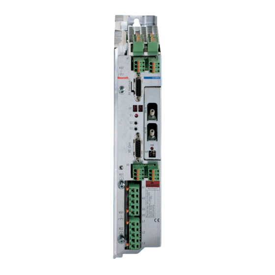
- Manuals
- Brands
- Bosch Manuals
- Controller
- Rexroth EcoDrive 03
- Instruction manual
-
Contents
-
Table of Contents
-
Bookmarks
Quick Links
Electric Drives
and Controls
Hydraulics
Rexroth EcoDrive 03
Drive Controllers
DKC**.3-016
Instruction Manual
Linear Motion and
Assembly Technologies
Pneumatics
Service
R911320340
Edition 01
Related Manuals for Bosch Rexroth EcoDrive 03
Summary of Contents for Bosch Rexroth EcoDrive 03
-
Page 1
Electric Drives Linear Motion and and Controls Hydraulics Assembly Technologies Pneumatics Service Rexroth EcoDrive 03 R911320340 Edition 01 Drive Controllers DKC**.3-016 Instruction Manual… -
Page 2
About this Documentation Rexroth EcoDrive 03 Rexroth EcoDrive 03 Title Drive Controllers DKC**.3-016 Instruction Manual Type of Documentation DOK-ECODR3-DKC16*UL***-IB01-EN-P Document Typecode 120-1000-B363-01/EN Internal File Reference This documentation provides information on the installation and operation Purpose of Documentation of the described products, by persons trained and qualified to work with electrical installations. -
Page 3: Table Of Contents
Rexroth EcoDrive 03 DKC**.3-016 Contents Contents Important Notes Safety Instructions ……………………1-1 General Information……………………. 1-1 Contact with Electrical Parts………………..1-2 Handling and Assembly………………….1-2 Dangerous Movements ………………….1-2 Magnetic and Electromagnetic Fields ………………1-4 Hot Parts……………………..1-4 Appropriate Use……………………..1-4 Identification Type Code ……………………….
-
Page 4
Contents Rexroth EcoDrive 03 DKC**.3-016 DOK-ECODR3-DKC16*UL***-IB01-EN-P… -
Page 5: Important Notes
• If these documentations contain some information you do not understand, it is absolutely necessary that you ask Bosch Rexroth for explanation before you start working on or with the devices.
-
Page 6: Contact With Electrical Parts
Important Notes Rexroth EcoDrive 03 DKC**.3-016 Contact with Electrical Parts High electrical voltage! Danger to life, electric shock and severe bodily injury! • Follow general construction and safety regulations when working on power installations. • Before switching on the device, the equipment grounding conductor must have been…
-
Page 7
Rexroth EcoDrive 03 DKC**.3-016 Important Notes Dangerous movements can occur immediately after equipment is switched on or even after an unspecified time of trouble-free operation. The monitoring in the drive components will normally be sufficient to avoid faulty operation in the connected drives. Regarding personal safety, especially the danger of bodily harm and material damage, this alone cannot be relied upon to ensure complete safety. -
Page 8: Magnetic And Electromagnetic Fields
Important Notes Rexroth EcoDrive 03 DKC**.3-016 Magnetic and Electromagnetic Fields Health hazard for persons with heart pacemakers, metal implants and hearing aids in proximity to electrical equipment! • Persons with heart pacemakers and metal implants are not permitted to enter following…
-
Page 9: Identification
Rexroth EcoDrive 03 DKC**.3-016 Identification Identification Type Code Note: The following figure illustrates the basic structure of the type code. Our sales representative will help you with the current status of available versions. DKC 03.3 — 040 — 7 — FW…
-
Page 10: Scope Of Supply
Identification Rexroth EcoDrive 03 DKC**.3-016 Scope of Supply Type Connectors — type independent X.. Connectors — type dependent X.. DKC01.3-***-7 DKC02.3-***-7 DKC03.3-***-7 DKC04.3-***-7 DKC05.3-***-7 DKC06.3-***-7 DKC21.3-***-7 DKC22.3-***-7 Fig. 2-4: Connectors for DKC**.3-016-7-FW included in the scope of supply DOK-ECODR3-DKC16*UL***-IB01-EN-P…
-
Page 11: Ratings And Dimensions
Rexroth EcoDrive 03 DKC**.3-016 Ratings and Dimensions Ratings and Dimensions Description Symbol Unit DKC**.3-016 listing according UL-standard (UL) UL 508 C Canadian National Standard(s) C22.2 listing according CSA-standard (UL) No. 14-05 UL files (UL) E134201 Use in a pollution degree 2…
-
Page 12
Ratings and Dimensions Rexroth EcoDrive 03 DKC**.3-016 Description Symbol Unit DKC**.3-016 power dissipation at continuous current I out_cont Diss_cont continuous DC bus power P respectively (UL) DC_cont 1) 2) 3) housing dimension; see related dimension sheet also 4) 5) see fig. «Air inlet and outlet of drive controller»… -
Page 13: Reference Documentations
Rexroth EcoDrive 03 DKC**.3-016 Reference Documentations Reference Documentations Overview Title Type Document Typecode Servo Applications with 1,5 s Acceleration Selection lists DOK-ECODR3-SERV-GEN***-AUxx-MS-P Time Servo Applications with 400 ms Acceleration Selection lists DOK-ECODR3-SERV-WZM***-AUxx-MS-P Time Main drives with 2AD-, ADF and 1MB-motors…
-
Page 14
Reference Documentations Rexroth EcoDrive 03 DKC**.3-016 Title Type Document Typecode ECODRIVE03 Drive for Machine Tool Troubleshooting Guide DOK-ECODR3-SMT-02VRS**-WAR*-EN-P Applications With SERCOS-, Analog and Parallelinterface ECODRIVE03 Drive for General Automation Troubleshooting Guide DOK-ECODR3-SGP-01VRS**-WAxx-EN-P With SERCOS-, Analog and Parallel interface ECODRIVE03 Drive for General Automation… -
Page 15: Instructions For Use
Rexroth EcoDrive 03 DKC**.3-016 Instructions for Use Instructions for Use Overcurrent Protection Branch circuit protection has to be provided externally according to the maximum values (voltage and current or voltage and percent of FLA of the fuses [FLA: Full Load Ampacity]).
-
Page 16: Connection Diagram
Instructions for Use Rexroth EcoDrive 03 DKC**.3-016 Connection Diagram Rexroth EcoDrive 03 (DKC**.016) Fig. 5-2: Total connection diagram for DKC**.3-016 DOK-ECODR3-DKC16*UL***-IB01-EN-P…
-
Page 17: X1, Connections For Control Voltage
Rexroth EcoDrive 03 DKC**.3-016 Instructions for Use X1, Connections for control voltage Technical description of connector Illustration: Ap5382f1.FH7 Fig. 5-3: Connector X1 Design: Type No. of pins Design Spring contact 2 x 3 Bushing on connector Fig. 5-4: Design Connection cross section:…
-
Page 18
Instructions for Use Rexroth EcoDrive 03 DKC**.3-016 Note: • Exceeding allowed control voltage generates error message «+24 volt error». (=> See also functional firmware description.) • Control voltage failure causes the running motor to coast torque-free (without brake). Dangerous movements due to unbraked coasting of motor with control voltage failure! ⇒… -
Page 19
Rexroth EcoDrive 03 DKC**.3-016 Instructions for Use Inputs Input voltage: min. max. AH and RF: High 16 V 30 V -0.5 V Input resistance 13.3 kOhm ±5% Reaction time See functional firmware description Fig. 5-9: Inputs The drive halt function is used to bring an axis to standstill with defined acceleration and jerk (see functional firmware description). -
Page 20: Connection Of Control Interfaces And Terminals
Instructions for Use Rexroth EcoDrive 03 DKC**.3-016 Connection of Control Interfaces and Terminals See Project Planning Manual for more details. X5, Motor and Mains Connections Lethal electric shock caused by live parts with more than 50 V! ⇒ Before working on the drive controller, switch off the power supply via the main switch or the fuse.
-
Page 21
Rexroth EcoDrive 03 DKC**.3-016 Instructions for Use Motor connection Connection Motor: device-external device-internal motor connection AP5398f1.FH7 Fig. 5-14: Motor connections Use Rexroth motor power cables to connect motor and controller. Cable Motor: Note: For technical data on connections and cross sections, see the motor Project Planning Manual. -
Page 22: X6, Motor Temperature Monitoring And Holding Brakes
Instructions for Use Rexroth EcoDrive 03 DKC**.3-016 Mains connections The mains connector serves as the connection of the drive controller with the power supply. Single-phase mains connection: device-external device-internal n.c. AP5399f1.FH7 Fig. 5-16: Single-phase mains connection Three-phase mains connection: device-external device-internal AP5400f1.FH7…
-
Page 23
Rexroth EcoDrive 03 DKC**.3-016 Instructions for Use Damages by exchanging the connectors X6.1-3 and X6.4-6! Do not exchange connectors X6.1-3 and X6.4-6. ⇒ Only use lines with sufficient cross section. ⇒ CAUTION Strong mechanical influence on the test tap of the ⇒… -
Page 24
5-10 Instructions for Use Rexroth EcoDrive 03 DKC**.3-016 Holding brake (BR+, BR-) Dangerous movements! Danger to personnel from falling or dropping axes! The standard equipment motor brake or an external ⇒ brake controlled directly by the servo drive are not… -
Page 25
5-11 Rexroth EcoDrive 03 DKC**.3-016 Instructions for Use to the central ground Ap5385f1.fh7 Fig. 5-24: Shared voltage source for brakes and control voltage supply Note: Looping through the voltages to other drive controllers is impossible. Other drive controllers have to be connected in radial arrangement around the voltage source. -
Page 26: X10, Ecox Expansion Interface
5-12 Instructions for Use Rexroth EcoDrive 03 DKC**.3-016 Basic connection of motor power, holding brake and motor temperature monitoring X5_M A1 A2 A3 AC-Motor Temperature Holding dependent resistance brake AP5387F1.FH7 Fig. 5-25: Connection of motor cable, holding brake and temperature monitor…
-
Page 27: Xe1, Xe2 Protective Conductor Connections For Motor And Mains
5-13 Rexroth EcoDrive 03 DKC**.3-016 Instructions for Use Expansion interface Connection device external device internal Expansion interface: IAN+ IAN+ IAN- IAN- IAN+ IAN- AP5376F1.FH7 Fig. 5-29: Expansion interface EcoX-Bus: drive or drive or E/A- E/A- drive module module IAN+ 120 R…
-
Page 28: Xs1, Xs2, Xs3 Shield Connections
5-14 Instructions for Use Rexroth EcoDrive 03 DKC**.3-016 Tightening torque: min. tightening torque max. tightening torque [Nm] [Nm] Fig. 5-32: Tightening torque Connection cross section: Cross section Max. connectable Max. wire size single wire cross section in AWG [mm²] in mm²…
-
Page 29: Installation
5-15 Rexroth EcoDrive 03 DKC**.3-016 Instructions for Use • Key for resetting diagnostic displays of errors • Key for updating firmware S2, S3 Switch for setting the drive address. Two decade switches are used to set the drive address. It can be set to Address switch S2, S3;…
-
Page 30: Sizing Of Enclosure And Control Cabinet
5-16 Instructions for Use Rexroth EcoDrive 03 DKC**.3-016 • Lay signal lines separately from the load resistance lines because of the occurrence of interference. • Transmit analog signals (e.g. command values, actual values) via shielded lines. • Do not connect mains, DC bus or power leads to low voltages or allow them to come into contact with these.
-
Page 31
5-17 Rexroth EcoDrive 03 DKC**.3-016 Instructions for Use Fig. 5-35: Example of arrangement for multiple-line structure with components Arrangement of Cooling Units Possible damage to the drive controller Operational safety of the machine endangered! Note the following instructions! CAUTION Due to the operating principle, condensation water is formed when cooling… -
Page 32
5-18 Instructions for Use Rexroth EcoDrive 03 DKC**.3-016 incorrect correct control cabinet control cabinet air inflow air inflow air outflow duct cooling cooling unit unit electronic electronic equip. equip. Eb0002f1.fh7 Fig. 5-37: Arranging the cooling unit at the front of the control cabinet… -
Page 33
Rexroth EcoDrive 03 DKC**.3-016 Index Index 24V control voltage supply (DKC**.3-016) 5-3 Address switch (DKC**.3-016) 5-14 Appropriate Use 1-4 Bb 5-5 DKC**.3-016 5-5 Connection cross section X1 5-3 X10 5-12 Connection Diagram 5-2 Connection length X10 5-13 Connections 5-1 control cabinet… -
Page 34
Index Rexroth EcoDrive 03 DKC**.3-016 Motor holding brake (DKC**.3-016) 5-11 Motor power cables (DKC**.3-016) 5-7 Motor temperature monitoring (DKC**.3-016) 5-8 Motor temperature monitoring (TM+, TM) (DKC**.3-016) 5-9 Overcurrent protection 5-1 Protective conductor connections XE1, XE2 5-13 Ratings 3-1 Ready to operate contact DKC**.3-016 5-5… -
Page 36
Bosch Rexroth AG Electric Drives and Controls P.O. Box 13 57 97803 Lohr, Germany Bgm.-Dr.-Nebel-Str. 2 97816 Lohr, Germany Phone +49 (0)93 52-40-50 60 +49 (0)93 52-40-49 41 service.svc@boschrexroth.de www.boschrexroth.com Printed in Germany…
Specifications:1325/1325356-ecodrive03.pdf file (07 Feb 2023) |
Accompanying Data:
REXROTH ECODRIVE03 Controller PDF Troubleshooting Manual (Updated: Tuesday 7th of February 2023 04:37:54 PM)
Rating: 4.1 (rated by 36 users)
Compatible devices: IndraDrive Fc FCS01, IndraDrive M, IndraControl L25 Series, CS 550i, IndraDrive Mi, EcoDrive 03, CS 520, VT-HACD-3-2 Series.
Recommended Documentation:
Text of Troubleshooting Manual
(Ocr-Read Version Summary of Contents, UPD: 07 February 2023)
-
84, 5-12 Description of Diagnostic Messages B…; C…, D… and A ECODRIVE03-SGP-03VRS DOK-ECODR3-SGP-03VRS**-WA01-EN-P Remedy: Check and set the relevant parameters correctly as follows: • S-0-0160, Acceleration data scaling type • S-0-0161, Acceleration data scaling factor • S-0-0162, Acceleration data scaling exponent • S-0-0116, Resolution of motor feedback �…
-
39, ECODRIVE03-SGP-03VRS Description of Diagnostic Messages F… and E… 4-9 DOK-ECODR3-SGP-03VRS**-WA01-EN-P F237 Excessive position command difference Cause: When the drive is operating in position control, incoming position command values are monitored. If the velocity required of the drive by two successive position command values is greater than or equal to the value in S-0…
-
7, ECODRIVE03-SGP-03VRS Contents III DOK-ECODR3-SGP-03VRS**-WA01-EN-P F878 Velocity loop error…………………………………………………………………………………………… 4-25 F879 Velocity limit S-0-0091 exceeded ……………………………………………………………………… 4-26 4.2 Warning Diagnostic Messages E…
-
73, REXROTH ECODRIVE03 ECODRIVE03-SGP-03VRS Description of Diagnostic Messages B…; C…, D… and A 5-1 DOK-ECODR3-SGP-03VRS**-WA01-EN-P 5 Description of Diagnostic Messages B…; C…, D… and A 5.1 Command Diagnostic Messages B…, C… and D… The commands are used for control of complex features in the drive. For example, the features «drive controlled homin…
-
47, REXROTH ECODRIVE03 ECODRIVE03-SGP-03VRS Description of Diagnostic Messages F… and E… 4-17 DOK-ECODR3-SGP-03VRS**-WA01-EN-P 3. SERCOS: problem in SERCOS interface (general) 4. Fieldbus: bus connection terminated/blocked longer than watchdog duration 5. The bus master is no longer sending cyclic telegrams to the drive, although they are expected in phase 4. Remedy for: 1. All fib…
-
57, ECODRIVE03-SGP-03VRS Description of Diagnostic Messages F… and E… 4-27 DOK-ECODR3-SGP-03VRS**-WA01-EN-P 4.2 Warning Diagnostic Messages E… Many areas are monitored in connection with operating modes and parameter settings. As a result, if a state is discovered which is still allowed by the order of operation, but in continuous operation generates an error and…
-
17, ECODRIVE03-SGP-03VRS Important directions for use 2-1 DOK-ECODR3-SGP-03VRS**-WA01-EN-P 2 Important directions for use 2.1 Appropriate use Introduction Rexroth Indramat products represent state-of-the-art developments and manufacturing. They are tested prior to delivery to ensure operating safety and reliability. The products may only be used in the manner that is defined as appro…
-
89, ECODRIVE03-SGP-03VRS Description of Diagnostic Messages B…; C…, D… and A 5-17 DOK-ECODR3-SGP-03VRS**-WA01-EN-P Cause: 1. The command should not have been activated. 2. The contacted motor or the external measurement system was not executed as an absolute encoder. Remedy for: 1. Stop execution of the command. 2. Equip the motor or external measurement system with an absolute …
-
26, REXROTH ECODRIVE03 3-8 Safety Instructions for Electric Drives and Controls ECODRIVE03-SGP-03VRS DOK-ECODR3-SGP-03VRS**-WA01-EN-P DANGER Dangerous movements! Danger to life, risk of injury, severe bodily harm or material damage! Ensure personal safety by means of qualified and tested higher-level monitoring devices or measures integrated in the installation. Unintended machine mot…
-
13, ECODRIVE03-SGP-03VRS Diagnostic Message Descriptions 1-1 DOK-ECODR3-SGP-03VRS**-WA01-EN-P 1 Diagnostic Message Descriptions 1.1 Overview of the Diagnostic Message Descriptions Diagnostic Message Types Each operational state of the drive will be characterized with a diagnostic message. Differentiations will be made between: • Error diagnostic messages • W…
-
72, REXROTH ECODRIVE03 4-42 Description of Diagnostic Messages F… and E… ECODRIVE03-SGP-03VRS DOK-ECODR3-SGP-03VRS**-WA01-EN-P E881 Mains fault Cause: The mains voltage has failed for at least three mains cycles during operation. Mains errors and undervoltage errors were set as fatal warnings in parameter P-0-0118, Power off on error. The drive switches the motor off. Remedy: C…
REXROTH ECODRIVE03 Recommended Instructions:
AX2120T, OS187, PS555 series, KMM-361SD, Kenlift, Conexis L1


-
Epever
LandStar LPLI Series
BEIJING EPSOLAR TECHNOLOGY CO., LTD. Tel:+86-10-82894112 / 82894962 Website:www.epsolarpv.com/www.epever.com 1 2 LandStar LPLI Series Solar Charge Controller …
LandStar LPLI Series 2
-
Corelis
NetUSB-1149.1
Artisan Technology Group is your source for quality new and certied-used/pre-owned equipment• FAST SHIPPING AND DELIVERY• TENS OF THOUSANDS OF IN-STOCK ITEMS• EQUIPMENT DEMOS• HUNDREDS OF MANUFACTURERS SUPPORTED• LEASING/MONTHLY RENTALS• ITAR CERTIFIED SECURE ASSET SOLUTIONSSERVICE CENTER REPAIRSExperienced engineers and technicians on staff at our full-s …
NetUSB-1149.1 57
-
NuAire
DRI-ECO-4S
113. 10. 20. Document Number 671791Nuaire | Western Industrial Estate | Caerphilly | CF83 1NA | nuaire.co.ukDRI-ECO-4S4 Way Switch For DRI-ECO Units With RF Control Installation ManualEMC Directive 2014/30/EULVD Directive 2014/35/EU1.0 SAFETY INFORMATION• This appliance should not be used by children or persons with reduced physical, sensory or mental capabilities o …
DRI-ECO-4S 3
-
oventrop
Hydromat DTR
Valves, controls + systemsDifferential pressure regulator “Hydromat DTR”Installation and operating instructions for the specialised installerRead installation and operating instructions in their entirety before installing the differential pressure regulator!Installation, initial operation, service and maintenance must only be carried out by qualied tradesmen!The installation and …
Hydromat DTR 16
-
Altronix
MAXIMAL FIT MaxFit7F8AP
MaxFit7F8AP8 Door Kit with Fused Outputs Fully assembled kit includes: — One (1) eFlow104NB — Power Supply/Charger — One (1) ACM8 — Fuse Protected Access Power Controller — One (1) PD8UL — Fuse Protected Power Distribution Module — BC750 enclosureMaxFit7F16AP16 Door Kit with Fused Outputs Fully assembled kit includes: — One (1) eFlow104NB — Power Supply/Charger — Two (2) ACM8 — Fuse P …
MAXIMAL FIT MaxFit7F8AP 8
-
WAREMA
LONMSE 2M230I
User and installation guideLONMSE 2M230I / 4M230I 0,25APlease save these instructions for future use!Valid as from May 1, 2005930426S0•816857•7995k0•18.04.2005930426S0•816857•7995k0•18.04.2005We reserve the right to carry out improvements1General remarksFig. 1: LONMSE 2M230I / 4M230IThe LONMSE 2M230I is a LON® actuator for central and local operation of up to two su …
LONMSE 2M230I 4
-
Baldor
VS1SP
STATUSSTOPLOCALDIAG 0r MAIN0.0V0RPM0.0A0.0HZBASICSTATUS F1601T1 BACKCONTROL TYPEV/F ControlMOTOR CONTROLLEVEL 1 BLOCKSLEVEL 2 BLOCKSLEVEL 3 BLOCKSMODIFIED PARAMSLINEAR LISTEV. LOGECARTSUTATS LOW INITIAL BUS0 4-Jul-06 09:35:00LOCALSTOPEV. LOG0.00r MAINOPTION B OARDSOPTION 1 EthernetOPTION 2 NoneFEEDBACKNoneDIAGSTOPLOCALPROGKEYPAD SETUPDIAG F1313T1 BACKKEYPAD CONTRAST50%StatusBasicPa …
VS1SP 2
-
Flycolor
Raptor390 Tower-20A
ATTENTION01 Main features02 Specification 03 Part list / Install DimensionsRaptor390 Tower Raptor390 4in1 ESCFlight controllerNylon Nut M3Nylon spacer M3*5+6Nylon screw M3*12123451148412345Frame(For referen ce)04 Wiring diagram of ESC and FC receiving mode 15.130.530.541.53636Install Dimensions(mm)The flight controller additional provide:One 10p …
Raptor390 Tower-20A 2
-
HomeMatic
HM-LC-Sw1-FM
Installations- und BedienungsanleitungSchalt-/Jalousieaktoren Unterputzmontage:HM-LC-Sw1-FM, HM-LC-Sw2-FMHM-LC-Bl1-FM Seite 4 — 25Installation and Operating ManualSwitch-/blind actuatorsflush-mount:HM-LC-Sw1-FM, HM-LC-Sw2-FM HM-LC-Bl1-FM Page 26 — 47DGB …
HM-LC-Sw1-FM 48
Additional Information:
Popular Right Now:
Operating Impressions, Questions and Answers:
|
|
Ремонт сервоприводов REXROTH INDRAMAT indradrive в Тольятти
 Ремонт сервоприводов REXROTH INDRAMAT indradrive в Тольятти, одна из многих услуг предлагаемых сервисным центром «РемПромЭл». Сервопривод относится к сложной промышленной электронике и состоит из двух взаимосвязанных составляющих- это электронная и силовая часть. Подобное конструктивное исполнение значительно усложняет ремонт сервоприводов REXROTH.
Сервопривода достаточно распространенное промышленное оборудование, и как все подвержены износу. В зависимости от интенсивности использования, нагрузки, среды в которой работает оборудования сервопривода выходят из строя останавливая рабочий процесс.
В целях сомнительной «экономии» некоторые пытаются провести ремонт сервоусилителя BOSCH REXROTH INDRAMAT indradrive самостоятельно на территории производства. Зачастую данные действия приводят к значительному удорожанию ремонта а при самом неблагоприятном исходе могут привести к не ремонтопригодности сервопривода.
В виду вышесказанного, настоятельно рекомендуем, не пытайтесь проводить ремонт сервоприводов BOSCH REXROTH своими силами, обратитесь за помощью к специалистам. Современный специализированный сервисный центр имеет в наличии весь необходимый инструмент, включая специальное диагностическое оборудование, а компетентный персонал проведет качественный ремонт сервоприводов BOSCH REXROTH INDRAMAT indradrive в Тольятти, дополнительно сервисные центры дают гарантию на проведенные ремонтные работы.
Ремонт сервоприводов BOSCH REXROTH в СЦ «РемПромЭл»
 Ремонт сервоприводов BOSCH REXROTH в сервисном центре самое разумное и экономически выгодное решение. Грамотные специалисты со знанием дела проведут глубокую диагностику неисправного блока и последующий ремонт сервопривода BOSCH REXROTH в кратчайшие сроки. К написанному можно добавить то, что каждый без исключения ремонт сервопривода INDRAMAT indradrive в СЦ «РемПромЭл» проводится с применением оригинальных запасных частей.
В 2013-ом году специалистами компании был проведен первый ремонт сервопривода BOSCH REXROTH положивший начало дальнейшему развитию в данном направлении. За прошедшее время были отремонтированы сотни единиц промышленного оборудования и накоплен колоссальный, бесценный опыт в ремонте сервоприводов различных производителей.
Сервисный центр «РемПромЭл» оснащен самым современным диагностическим и ремонтным оборудованием, имеются в наличии расходные материалы, а так же на складе компании богатый выбор оригинальных запасных частей, что дает возможность провести качественный ремонт сервоприводов BOSCH REXROTH INDRAMAT indradrive.
Обратившись в СЦ за ремонтом сервоприводов вы получите:
- Глубокую диагностику с выявлением неисправного компонента;
- Чистку неисправного блока;
- Ремонт сервопривода BOSCH REXROTH в кратчайшие сроки;
- Настройка сервоусилителя;
- Проверку отремонтированного блока на специальном стенде в условиях максимально приближенных к реальным;
- Видео проверки отремонтированного сервопривода.
Отдельное внимание мы уделяем качеству проведения ремонта и даем гарантию на ремонт сервоприводов BOSCH REXROTH INDRAMAT indradrive, а так же на замененные в процессе ремонта запасные части и расходные материалы 6 месяцев.
Настройка сервоусилителей BOSCH REXROTH INDRAMAT indradrive в Тольятти
 Настройка сервоприводов (сервоусилителей) — это заключительный этап ремонта и в тоже время очень важный. Для правильной работы восстановленного блока просто необходимо провести грамотное программирование сервоусилителя. Ремонт и дальнейшую настройку сервоприводов выполняют разные специалисты, так как подобная работа довольно сложная и имеет свою специфику.
Настройка сервоусилителей или как еще называют программирование сервоприводов, неотъемлемая часть процесса реанимирования, ввиду того, что ремонт силовой части это только половина мероприятий направленных на восстановление работоспособности сервоприводов.
В некоторых случаях возникает необходимость провести программирование сервоусилителя без его ремонта. Причин по которым может возникнуть подобная необходимость масса.
Настройка сервоуслилтелей в Тольятти может быть и отдельной услугой предоставляемой сервисным центром «РемПромЭл». Инженеры компании проведут необходимую настройку сервоприводов как на территории сервисного центра так и с выездом на территорию заказчика (по предварительной договоренности).
От качественной настройки сервоусилителя зависит правильная и безаварийная работа связки сервопривода и серводвигателя, а для этого требуется не много, просто программирование сервопривода должен проводить компетентный персонал с богатым опытом по настройке сервоуслилтелей.
Подключение сервопривода BOSCH REXROTH
 Подключение сервопривода BOSCH REXROTH к оборудованию заказчика это еще одна услуга предоставляемая нашей компанией.
При необходимости специалист центра выполнит подключение сервоприводаBOSCH REXROTH INDRAMAT indradrive с выездом на территорию заказчика.
В некоторых случаях на производстве может быть дефицит квалифицированны кадров которые могли бы произвести качественное подключение сервопривода, именно по этому мы предлагаем услуги нашего сервисного центра.
Свяжитесь с нашими менеджерами, закажите выезд специалиста, и подключением сервопривода BOSCH REXROTH займется инженер сервисного центра. В случае заказа на подключение сервопривода BOSCH REXROTH INDRAMAT indradrive силами наших специалистов вы получаете гарантию качества и работоспособности вашего оборудования.
Доверяя работу по подключению сервопривода BOSCH REXROTH профессионалам, вы избавляетесь от головной боли и гарантированно получаете работающее оборудование в кратчайшие сроки и за разумную цену.
Ошибки сервопривода Bosch Rexroth
 Каждый сервопривод, за редким исключением оснащен информационной панелью с помощью которой проходит процесс программирования сервоприводов, а так же на ней в случае нештатной ситуации отображается код ошибки которая привела к остановке оборудования.
У каждого производителя разные коды ошибок у кого то это могут быть цифровые обозначения у кого то буквенные, но вся прелесть заключается в том, что открыв документацию и расшифровав код ошибки сервопривода мы с большой долей вероятности можем исправить эту ошибку на месте, сбросить ее на сервоприводе и запустить оборудование заново.
К сожалению не все ошибки сервоприводов можно исправить и сбросить самостоятельно, в некоторых случаях придется обращаться к специалистам сервисного центра.
Самые распространенные ошибки сервоприводов:
- Превышение тока;
- Перенапряжение или недостаточное напряжение;
- Перегрузка;
- Ошибка сигнала энкодера;
- Превышение температуры IGBT-модуля ;
- Ошибка связи;
- Обрыв фазы питания;
- Короткое замыкание.
Это не полный список распространенных ошибок сервоприводов которые можно сбросить самостоятельно без обращения к специалистам.
Коды ошибок сервопривода Bosch Rexroth IndraDrive MPx-02 to MPx-08
Дисплеи F8030 и F8135
|
Дисплей |
E-код канал 1 (P3219 [0]) |
E-код канал 2 (P3219 [1]) |
Описание ошибки |
|---|---|---|---|
| F8030 | 113 | Разрешение привода установлено в состоянии внутренней ошибки. Ошибка «Безопасный останов 1». | |
| 114 | 637, 642 | Разрешение привода настраивается в функции техники безопасности «Безопасный останов 1». | |
| 115 | 638, 641 | Разрешение привода задается в функции техники безопасности «Безопасный останов 1 (Аварийный останов)». | |
| 303 | 639 | Разрешение движения устанавливается с помощью «парковочной оси». | |
| 669 | Разрешение привода все еще установлено при переходе к «Безопасный останов 1 (SS1)». | ||
| 670 | Разрешение привода все еще установлено при переходе к «Безопасный останов 1 (Аварийный останов) (SS1ES)». | ||
| F8134 | 273 | При переходе к ошибке «Безопасная остановка 1» рампа замедления упала ниже установленного значения в P-0-3282. |
|
| 405 | Безопасная система торможения и удержания: отсутствие обратной связи или тормоз управляемый приводом, включить отсутствующий. | ||
| 406 | Безопасная система торможения и удержания: Отсутствует управление резервным удерживающим тормозом без разрешения привода в состоянии покоя. | ||
| 408 | Безопасная система торможения и удержания: Отсутствует управление стояночным тормозом двигателя («P-0-3307, Техника безопасности — время задержки выключения «работает). | ||
| 235, 542 | Тормоз двигателя или резервный стояночный тормоз отпущен, хотя выходной каскад не активен. Устранение: Проверить управление тормозом. |
||
| F8135 | 205 | В функции техники безопасности «Безопасный останов 1» рампа замедления упала ниже установленного значения, для надежно контролируемого замедления (P-0-3282). |
|
| 207 | В функции техники безопасности «Безопасный останов 1 (Аварийный останов)» замедление рампа упала ниже значения, установленного для надежно контролируемого замедления (P-0-3282). |
||
| 272 | 566, 567, 586 |
При переходе к ошибке «Безопасная остановка 1» рампа замедления упала ниже установленного значения в P-0-3282. |
|
| 273 | Реакция на ошибку F7: При переходе к ошибке «Безопасный останов 1» рампа замедления упало ниже значения, установленного в P-0-3282. |
||
| 407 | Безопасная система торможения и удержания: Отсутствует управление резервным удерживающим тормозом. Причина: задержки из-за стояночного тормоза двигателя. |
||
| 410 | Превышено время безопасного останова, в результате реакции на ошибку, не удалось удалить привод, включить в течение времени P-0-3220 / P-0-3225 Устранение: Проверить параметрирование в P ‑ 0‑3220 / P ‑ 0‑3225 и S ‑ 0‑0207. |
||
| 412, 413 | 546, 623 | Безопасная система торможения и удержания: при замедлении с «значением команды скорости. сброс », темп замедления упал ниже значения, установленного в P-0-3282. |
|
| 619, 620 | В случае ошибки привод не может во время остановки, управляемой приводом, остановится в параметризованных пределах контроля. Ошибка генерируется до P-0-3226 закончился. |
Диагностический дисплей от MPB-07V12 / MPx-08VRS
|
Светодиод |
Значение | Устранение |
|---|---|---|
|
Off
|
|
|
|
Мигает зеленый
|
|
|
|
Горит зеленый
|
|
|
|
Мигает зеленый-желтый
|
|
|
|
Мигает желтый
|
|
|
|
Горит желтый
|
|
|
|
Мигает красный-желтый
|
|
|
|
Мигает красный-зеленый
|
|
|
|
Мигает красный
|
Ошибка (F2xxx, F3xxx, F6xxx, F7xxx, F8xxx). | Прочтите точный статус через «S ‑ 0‑0095», (диагностическое сообщение). Обратитесь в сервисный центр. |
|
Горит красный
|
|
|
Все возможные ошибки сервопривода Bosch Rexroth IndraDrive MPx-02 to MPx-08 — Скачать в формате DDF
Типы сервоприводов Bosch Rexroth
| Сервопривод | Тип сервопривода |
|---|---|
|
BOSCH REXROTH INDRAMAT indradrive |
HCS02.1E-W0070-A-03-NNNN; HMD01.1N-W0036; HCS01.1E-W0008-A-03; DKC02.3-018-3-MGP-01VRS; DKCXX.3-100-7; HCS01.1E-W0028-A-03; HMS01.1N-W0020; HMD01.1N-W0020 |
Указанные в таблице типы сервоприводов BOSCH REXROTH INDRAMAT это далеко не все, мы предлагаем качественный ремонт сервоприводов в Тольятти абсолютно любых производителей и года выпуска.
Оставить заявку на ремонт сервопривода BOSCH REXROTH INDRAMAT indradrive
У вас есть проблемы с сервоприводом? Вам нужен срочный ремонт сервопривода BOSCH REXROTH INDRAMAT indradrive или его настройка? Оставьте заявку на ремонт сервопривода BOSCH REXROTH в Тольятти воспользовавшись одноименной кнопкой на сайте либо обратитесь к нашим менеджерам. Связаться с ними можно несколькими способами:

- Заказав обратный звонок (кнопка в правом верхнем углу сайта)
- Посредством чата (кнопка расположена с левой стороны сайта)
- Позвонив по номеру телефона: +7(927)610-78-70; +7(848)255-80-30
- Написав на электронную почту: Адрес электронной почты защищен от спам-ботов. Для просмотра адреса в вашем браузере должен быть включен Javascript.
- Перейти в начало статьи