
|
|
Ремонт сервопривода Delta
 Сервисный центр «Кернел» предлагает выполнить качественный ремонт сервопривода Delta в на компонентном уровне в максимально сжатые сроки. Сервопривод относятся к сложной промышленной электронике именно поэтому ремонтом сервоприводов Delta, впрочем, как и других производителей должны заниматься специалисты, имеющие не только высшее техническое образование, но и солидный опыт в ремонте подобной промышленной электроники.
Также для восстановления подобного промышленного оборудования понадобится хорошая материально-техническая база. При выполнении всех выше перечисленных условий, шансы на успешный ремонт сервопривода Delta возрастают в геометрической прогрессии.
Именно поэтому за ремонтом сервоприводов, независимо от производителя лучше всего обращаться в специализированный сервисный центр, который отвечает всем техническим требованиям, такой как Кернел. Наш цент имеет отличную материально-техническую базу, а за время существования с 2002 года специалисты компании накопили бесценный опыт в том числе опыт в ремонте сервоприводов Delta.
Особенности ремонта сервопривода Delta
Ремонт сервоприводов Delta имеет ряд индивидуальных особенностей, это связано с конструктивными особенностями данного промышленного оборудования. По аналогии с частотными преобразователями они состоят из двух взаимосвязанных частей, это:
- Аппаратная часть;
- Программная часть.
В первую очередь ремонтируется аппаратная часть промышленного сервопривода. После глубокой диагностики неисправного блока выявляются все неисправные компоненты, которые в последствии заменяются на оригинальные запасные части (по возможности), в случае если сервопривод уже давно снят с производства и найти оригинальные запчасти просто невозможно они заменяются на аналоги.
Данный вид ремонта называется компонентным. От других видов его отличает две немаловажные детали.
- Значительное удешевление ремонта;
- Существенное сокращение времени ремонта.
По завершении ремонта аппаратной части сервопривода наступает очередь программной. В зависимости от серии выбирается программный продукт и зашивается в блок.
Заключительный этап ремонта сервопривода Delta это проверка на специализированном стенде. Все блоки проверяются без нагрузки и с нагрузкой не менее двух часов.
Коды предупреждений и ошибок сервопривода Delta
При обнаружении неисправности при работе сервопривода будет активирована соответствующая защита и выведено предупреждающее сообщение на индикатор сервоусилителя или цифрового пульта. Коды неисправностей приведены в файле PDF который доступен по ссылке ниже.
Дополнительно в файле указаны способы устранения неисправностей сервопривода Delta и их сброс.
Посмотреть все коды ошибок сервопривода Delta
Схемы
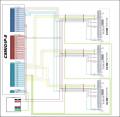
В некоторых случает может понадобится схема подключения сервоприводов, ниже мы показаны схемы сервопривода Delta.
Схемы типовых подключений сервоприводов Delta
|
Сервопривод Delta Режим управления положением |
Сервопривод Delta Режим управления скоростью |
|
|

|
|
Сервопривод Delta Режим управления моментом |
|

|

Базовые схемы соединений сервоприводов Delta
|
Базовая схема соединений для моделей мощностью 400Вт и ниже (без встроенного тормозного резистора и без вентилятора) |
Базовая схема соединений для моделей мощностью 750Вт (со встроенным тормозным резистором но без вентилятора) |
|
|
")
|
|
Базовая схема соединений для моделей мощностью 1 – 2кВт (со встроенным тормозным резистором и вентилятором) |
|
")
|
")
Конфигурация и подключение сервоприводов Delta
|
Соединение с внешними устройствами сервоприводов Delta, конфигурация |
|

|
|
|
Подключение сервопривода Delta к однофазному источнику питания (модели 1.5кВт и ниже) |
Подключение сервопривода Delta к трехфазному источнику питания (модели 2кВт и выше) |
|
|

|

Преимущество ремонта сервоприводов Delta в нашем сервисном центре
Во время эксплуатации электроприводов Delta может возникнуть проблема, далеко не всегда возникшую проблему можно исправить на месте своими силами, наш сервисный центр готов вам в этом помочь, выполнив качественный ремонт сервоприводов Delta в сжатые сроки с полугодовой гарантией.
Мы не только восстановим неисправный блок, но и подскажем как действовать в той или иной ситуации для максимально долгой и безаварийной работы сервопривода.
Работы, проводимые при ремонте сервопривода Delta:
![]()
- Предварительный осмотр на возможность восстановления бесплатный;
- Мы производим ремонт сервопривода Delta на компонентном уровне (экономия бюджета и времени);
- При ремонте сервоприводов ни каких конструктивных изменений не вносим;
- Ремонт блоков с применением оригинальных запасных частей (по возможности);
- Вы платите исключительно за результат — работающий сервопривод;
- Гарантия на ремонт сервопривода Delta и на запасные части замененные в процессе ремонта 6 месяцев;
- Сроки ремонта варьируются от 5 до 15 рабочих дней.
За два десятилетия существования сервисного центра нашими специалистами были успешно проведены тысячи подобных ремонтов с каждым разом поднимая квалификацию наших инженеров. Ниже представлен далеко не полный список сервоприводов Delta серии ASDA-B2 и ASDA-AB ремонтируемые в нашем сервисном центре.
|
Серия ASDA-B2 |
|
|
ASD-B2-0121-B |
Ремонт сервопривода Delta мощностью 0.1кВт. |
|
ASD-B2-0221-B |
Ремонт сервопривода Delta мощностью 0.2кВт. |
|
ASD-B2-0421-B |
Ремонт сервопривода Delta мощностью 0.4кВт. |
|
ASD-B2-0721-B |
Ремонт сервопривода Delta мощностью 0.75кВт. |
|
ASD-82-1021-B |
Ремонт сервопривода Delta мощностью 1кВт. |
|
ASD-B2-1521-B |
Ремонт сервопривода Delta мощностью 1.5кВт. |
|
ASD-B2-2023-B |
Ремонт сервопривода Delta мощностью 2кВт. |
|
ASD-B2-3023-B |
Ремонт сервопривода Delta мощностью 3кВт. |
|
Серия ASDA-AB |
|
|
ASD-A2R-0121-F |
Ремонт сервопривода Delta мощностью 0.1кВт. |
|
ASD-A2R-0221-F |
Ремонт сервопривода Delta мощностью 0.2кВт. |
|
ASD-A2R-0421-F |
Ремонт сервопривода Delta мощностью 0.4кВт. |
|
ASD-A2R-0721-F |
Ремонт сервопривода Delta мощностью 0.75кВт. |
|
ASD-A2R-1021-F |
Ремонт сервопривода Delta мощностью 1кВт. |
|
ASD-A2R-1521-L |
Ремонт сервопривода Delta мощностью 1.5кВт. |
|
ASD-A2-2043-M |
Ремонт сервопривода Delta мощностью 2кВт. |
|
ASD-A2-3043-M |
Ремонт сервопривода Delta мощностью 3кВт. |
|
ASD-A2-4543-M |
Ремонт сервопривода Delta мощностью 4.5кВт. |
|
ASD-A2-5543-U |
Ремонт сервопривода Delta мощностью 5.5кВт. |
В таблице представлен далеко не полный список сервоприводов Delta серии ASDA-B2 и ASDA-AB ремонт которых мы вам предлагаем, также специалисты нашей компании ремонтируют сервопривода не зависимо от серии и под каким брендом они были выпущены.
Оставить заявку на ремонт сервопривода Delta
У вас остались вопросы, связанные с ремонтом или сбросом ошибок, а также программированием и настройкой сервоприводов Delta? Оставьте заявку на ремонт сервопривода Delta в менеджерам. Связаться с ними можно несколькими способами:

- Заказав обратный звонок (кнопка в правом нижнем углу сайта)
- Посредством чата (кнопка расположена с левой стороны сайта)
- Позвонив по номеру телефона:
- +7(8482) 79-78-54;
- +7(8482) 55-96-39;
- +7(917) 121-53-01
- Написав на электронную почту: 89171215301@mail.ru
За время существования сервисного центра нашими специалистами были отремонтированы тысячи единиц промышленной электроники. Вот далеко не полный список производителей промышленной электроники и оборудования, ремонтируемой в нашей компании.
<= See All alarms of Delta servo
| Name | Description | ALM | WRN | SRV ON | Clear Way |
|---|---|---|---|---|---|
|
AL.009 |
Position error exceeds P2-35 | ⊗ | NO | DI.ARST |
| Causes | Checking Method | Actions |
|---|---|---|
| Parameter P2-35 is set too small | Check the setting value of parameter P2-35 (The warning condition of excessive position deviation) | Increase the setting value of P2-35 (The warning condition of excessive position deviation) |
| The setting of the gain value is too small | Check if the setting value is appropriate | Correctly adjust the gain value |
| The torque limit is too low | Check the torque limit value | Correctly adjust the torque limit value |
| Excessive external load | Check the external load | Reduce the external load or evaluate the motor capacity again |
| Improper setting of E-gear ratio | Make sure if the proportion of P1-44 and P1-45 is appropriate | Correctly setup E-gear ratio |
(The above information is referenced from Delta Electronics IMSBU)
↓ The following content is contributed by users ↓
| Other reasons | Checking Method | Actions |
|---|---|---|
| Speed limit P1-55 too small(Archer) | Check if position cmd frequency exceeds P1-55 with Scope of ASDA-Soft | increase P1-55 |
| power line U, V, W is disconnected(Archer) | Check if the power line U, V, W is disconnected or is in poor contact? | |
| inproper cmd from the host controller(yujan) | position cmd from communication is too far from the current position | check the program of the host controller |
— Sharing is a virtue. Please add the inadequacies of this article to benefit the public —
ASDA-A2
AL008:Abnormal Pulse Command
Causes
The pulse command
frequency is higher than
the rated input
frequency.
AL009:Excessive Deviation of Position Command
Causes
Parameter P2-35 is set
too small
The setting of the gain
value is too small.
The torque limit is too
low.
Excessive external load
Improper setting of E-
gear ratio
AL011:Encoder Error
Causes
Wrong wiring of the
encoder
The encoder is loose
Bad connection of the
encoder
The encoder is damaged Check if the motor is damaged
AL012:Adjustment Error
Causes
The analog input contact
is incorrectly set back to
zero
The detection device is
damaged
AL013:Emergency Stop
Causes
Press the emergency
stop button
10-12
Checking Method
Use the scope to check if the input
frequency is over the rated input
frequency.
Checking Method
Check the setting value of
parameter P2-35 (The warning
condition of excessive position
deviation)
Check if the setting value is
appropriate
Check the torque limit value
Check the external load
Make sure if the proportion of P1-44
and P1-45 is appropriate.
Checking Method
Check if the wiring follows the
suggested wiring of the user
manual.
Check the drive connector of CN2
and encoder
Check if the connection between
CN2 of the drive and the encoder of
the servo motor is loose
Checking Method
Measure if the voltage of the analog
input contact is the same as the
ground voltage
Reset the power supply
Checking Method
Check if the emergency stop button
is enabled.
Chapter 10 Troubleshooting
Corrective Actions
Correctly set the input pulse
frequency.
Corrective Actions
Increase the setting value of P2-35
(The warning condition of
excessive position deviation)
Correctly adjust the gain value
Correctly adjust the torque limit
value
Reduce the external load or
evaluate the motor capacity again
Correctly setup E-gear ratio
Corrective Actions
Correct wiring
Install the encoder again
Reconnect the wiring
Change the motor
Corrective Actions
Correctly ground the analog input
contact
If the error still occurs after reset,
send the drive back to the
distributors or contact with Delta.
Corrective Actions
Activate emergency stop
Revision February, 2017
|
|
Ремонт сервопривода Delta
Сервисный центр «Кернел» предлагает выполнить качественный ремонт сервопривода Delta в на компонентном уровне в максимально сжатые сроки. Сервопривод относятся к сложной промышленной электронике именно поэтому ремонтом сервоприводов Delta, впрочем, как и других производителей должны заниматься специалисты, имеющие не только высшее техническое образование, но и солидный опыт в ремонте подобной промышленной электроники.
Также для восстановления подобного промышленного оборудования понадобится хорошая материально-техническая база. При выполнении всех выше перечисленных условий, шансы на успешный ремонт сервопривода Delta возрастают в геометрической прогрессии.
Именно поэтому за ремонтом сервоприводов, независимо от производителя лучше всего обращаться в специализированный сервисный центр, который отвечает всем техническим требованиям, такой как Кернел. Наш цент имеет отличную материально-техническую базу, а за время существования с 2002 года специалисты компании накопили бесценный опыт в том числе опыт в ремонте сервоприводов Delta.
Особенности ремонта сервопривода Delta
Ремонт сервоприводов Delta имеет ряд индивидуальных особенностей, это связано с конструктивными особенностями данного промышленного оборудования. По аналогии с частотными преобразователями они состоят из двух взаимосвязанных частей, это:
- Аппаратная часть;
- Программная часть.
В первую очередь ремонтируется аппаратная часть промышленного сервопривода. После глубокой диагностики неисправного блока выявляются все неисправные компоненты, которые в последствии заменяются на оригинальные запасные части (по возможности), в случае если сервопривод уже давно снят с производства и найти оригинальные запчасти просто невозможно они заменяются на аналоги.
Данный вид ремонта называется компонентным. От других видов его отличает две немаловажные детали.
- Значительное удешевление ремонта;
- Существенное сокращение времени ремонта.
По завершении ремонта аппаратной части сервопривода наступает очередь программной. В зависимости от серии выбирается программный продукт и зашивается в блок.
Заключительный этап ремонта сервопривода Delta это проверка на специализированном стенде. Все блоки проверяются без нагрузки и с нагрузкой не менее двух часов.
Коды предупреждений и ошибок сервопривода Delta
При обнаружении неисправности при работе сервопривода будет активирована соответствующая защита и выведено предупреждающее сообщение на индикатор сервоусилителя или цифрового пульта. Коды неисправностей приведены в файле PDF который доступен по ссылке ниже.
Дополнительно в файле указаны способы устранения неисправностей сервопривода Delta и их сброс.
Посмотреть все коды ошибок сервопривода Delta
Схемы
В некоторых случает может понадобится схема подключения сервоприводов, ниже мы показаны схемы сервопривода Delta.
Схемы типовых подключений сервоприводов Delta
|
Сервопривод Delta Режим управления положением |
Сервопривод Delta Режим управления скоростью |
|
|
|
|
Сервопривод Delta Режим управления моментом |
|
|
|
Базовые схемы соединений сервоприводов Delta
|
Базовая схема соединений для моделей мощностью 400Вт и ниже (без встроенного тормозного резистора и без вентилятора) |
Базовая схема соединений для моделей мощностью 750Вт (со встроенным тормозным резистором но без вентилятора) |
|
|
|
|
Базовая схема соединений для моделей мощностью 1 – 2кВт (со встроенным тормозным резистором и вентилятором) |
|
|
|
Конфигурация и подключение сервоприводов Delta
|
Соединение с внешними устройствами сервоприводов Delta, конфигурация |
|
|
|
|
|
Подключение сервопривода Delta к однофазному источнику питания (модели 1.5кВт и ниже) |
Подключение сервопривода Delta к трехфазному источнику питания (модели 2кВт и выше) |
|
|
|
Преимущество ремонта сервоприводов Delta в нашем сервисном центре
Во время эксплуатации электроприводов Delta может возникнуть проблема, далеко не всегда возникшую проблему можно исправить на месте своими силами, наш сервисный центр готов вам в этом помочь, выполнив качественный ремонт сервоприводов Delta в сжатые сроки с полугодовой гарантией.
Мы не только восстановим неисправный блок, но и подскажем как действовать в той или иной ситуации для максимально долгой и безаварийной работы сервопривода.
Работы, проводимые при ремонте сервопривода Delta:
![]()
- Предварительный осмотр на возможность восстановления бесплатный;
- Мы производим ремонт сервопривода Delta на компонентном уровне (экономия бюджета и времени);
- При ремонте сервоприводов ни каких конструктивных изменений не вносим;
- Ремонт блоков с применением оригинальных запасных частей (по возможности);
- Вы платите исключительно за результат — работающий сервопривод;
- Гарантия на ремонт сервопривода Delta и на запасные части замененные в процессе ремонта 6 месяцев;
- Сроки ремонта варьируются от 5 до 15 рабочих дней.
За два десятилетия существования сервисного центра нашими специалистами были успешно проведены тысячи подобных ремонтов с каждым разом поднимая квалификацию наших инженеров. Ниже представлен далеко не полный список сервоприводов Delta серии ASDA-B2 и ASDA-AB ремонтируемые в нашем сервисном центре.
|
Серия ASDA-B2 |
|
|
ASD-B2-0121-B |
Ремонт сервопривода Delta мощностью 0.1кВт. |
|
ASD-B2-0221-B |
Ремонт сервопривода Delta мощностью 0.2кВт. |
|
ASD-B2-0421-B |
Ремонт сервопривода Delta мощностью 0.4кВт. |
|
ASD-B2-0721-B |
Ремонт сервопривода Delta мощностью 0.75кВт. |
|
ASD-82-1021-B |
Ремонт сервопривода Delta мощностью 1кВт. |
|
ASD-B2-1521-B |
Ремонт сервопривода Delta мощностью 1.5кВт. |
|
ASD-B2-2023-B |
Ремонт сервопривода Delta мощностью 2кВт. |
|
ASD-B2-3023-B |
Ремонт сервопривода Delta мощностью 3кВт. |
|
Серия ASDA-AB |
|
|
ASD-A2R-0121-F |
Ремонт сервопривода Delta мощностью 0.1кВт. |
|
ASD-A2R-0221-F |
Ремонт сервопривода Delta мощностью 0.2кВт. |
|
ASD-A2R-0421-F |
Ремонт сервопривода Delta мощностью 0.4кВт. |
|
ASD-A2R-0721-F |
Ремонт сервопривода Delta мощностью 0.75кВт. |
|
ASD-A2R-1021-F |
Ремонт сервопривода Delta мощностью 1кВт. |
|
ASD-A2R-1521-L |
Ремонт сервопривода Delta мощностью 1.5кВт. |
|
ASD-A2-2043-M |
Ремонт сервопривода Delta мощностью 2кВт. |
|
ASD-A2-3043-M |
Ремонт сервопривода Delta мощностью 3кВт. |
|
ASD-A2-4543-M |
Ремонт сервопривода Delta мощностью 4.5кВт. |
|
ASD-A2-5543-U |
Ремонт сервопривода Delta мощностью 5.5кВт. |
В таблице представлен далеко не полный список сервоприводов Delta серии ASDA-B2 и ASDA-AB ремонт которых мы вам предлагаем, также специалисты нашей компании ремонтируют сервопривода не зависимо от серии и под каким брендом они были выпущены.
Оставить заявку на ремонт сервопривода Delta
У вас остались вопросы, связанные с ремонтом или сбросом ошибок, а также программированием и настройкой сервоприводов Delta? Оставьте заявку на ремонт сервопривода Delta в менеджерам. Связаться с ними можно несколькими способами:
- Заказав обратный звонок (кнопка в правом нижнем углу сайта)
- Посредством чата (кнопка расположена с левой стороны сайта)
- Позвонив по номеру телефона: +7(8482) 79-78-54; +7(917) 121-53-01
- Написав на электронную почту: 89171215301@mail.ru
За время существования сервисного центра нашими специалистами были отремонтированы тысячи единиц промышленной электроники. Вот далеко не полный список производителей промышленной электроники и оборудования, ремонтируемой в нашей компании.
#1
![]()
OFFLINE
Elnurko
- Пол:Мужчина
- Город:Баку
- Интересы:Чпу , IT, Архитектура, Астрофизика.
- Из:Азербайджанская Республика
Отправлено 08 Декабрь 2016 — 02:47
доброго времени суток, давненько меня не было)))
ребят, такая проблема, есть станок с серваками DELTA ASD-B2
есть плата НЦСтудио Лямбда 5с
и так,
подключил как положено контакты от нцшки к серваку, снял сервоон задал значение для Электронного редуктора,
и все казалось бы заработало, но не тут то было, гадина вращяется в одном направлении сигнал поступает на драйвер, но вот как будто стоит запрет на реверс вращения, 3 дня уже копаю мануал по серваку без толку,
Серво привод рабочий так как в режиме джог работает как положено!
если надо могу дать русский мануал.
ребят кто имел дело с этими серваками, помогите плизз уже мозг плавиться)))
http://www.rts.ua/ca…_manual_rus.pdf
я думаю дело в настройках, но где именно не пойму((((
Прикрепленные изображения
-
0
Все сложное -просто!!!

- Наверх
#2
![]()
niksooon
- Пол:Мужчина
- Из:Кашира
Отправлено 08 Декабрь 2016 — 14:04
По памяти в заводских настройках для какого-то из дискретных входов стоит запрет на обратное вращение .
чтоб сильно голову не забивать -для входов которые не используются сбрось соответствующие параметры в ноль…..

у меня первый вход используется для включения драйва,а пятый это alarm reset…….. ,остальные входа не задействованы……
Сообщение отредактировал niksooon: 08 Декабрь 2016 — 15:16
-
0
Сделанное правильно — красиво. Если сделанное тебе не нравится — то и работать оно будет хреново. Перевари, пересверли, выпили заново — ну, или хотя бы покрась.
- Наверх
#3
![]()
Elnurko
- Пол:Мужчина
- Город:Баку
- Интересы:Чпу , IT, Архитектура, Астрофизика.
- Из:Азербайджанская Республика
Отправлено 08 Декабрь 2016 — 15:39
Спасибо)))
сегодня попробую , потом отпишусь
-
0
Все сложное -просто!!!
- Наверх
#4
![]()
Elnurko
- Пол:Мужчина
- Город:Баку
- Интересы:Чпу , IT, Архитектура, Астрофизика.
- Из:Азербайджанская Республика
Отправлено 08 Декабрь 2016 — 19:29
все ровно не работает(((
можно по подробнее что куда подключили и что где настроили???
-
0
Все сложное -просто!!!
- Наверх
#5
![]()
niksooon
- Пол:Мужчина
- Из:Кашира
Отправлено 08 Декабрь 2016 — 21:17
что и куда подключал вряд-ли поможет, тем более в мануале типовые схемы есть, все по ним делал . Выше уже написал и с картинкой как исключить из работы не используемые входы,дабы исключить их влияние.
проверьте еще параметр Р1-00 какой тип входного сигнала установлен,вдруг случаем CW( CCW) режим включен или еще что……
В принципе могу для пробы свой профиль настроек дать, но пользовать надо на свой страх и риск………..

delta_Niksooon.rar 2,02К
488 скачиваний
-
0
Сделанное правильно — красиво. Если сделанное тебе не нравится — то и работать оно будет хреново. Перевари, пересверли, выпили заново — ну, или хотя бы покрась.
- Наверх
#6
![]()
Elnurko
- Пол:Мужчина
- Город:Баку
- Интересы:Чпу , IT, Архитектура, Астрофизика.
- Из:Азербайджанская Республика
Отправлено 08 Декабрь 2016 — 22:16
Все победил, проблема была в Нцшке точнее распиновке
))))
Спасибо огромное))))
-
0
Все сложное -просто!!!
- Наверх
#7
![]()
niksooon
- Пол:Мужчина
- Из:Кашира
Отправлено 08 Декабрь 2016 — 22:23
Dir до драйва не доходил что-ли? даже предположить не мог что вы этот момент самостоятельно ранее не проверили………
-
0
Сделанное правильно — красиво. Если сделанное тебе не нравится — то и работать оно будет хреново. Перевари, пересверли, выпили заново — ну, или хотя бы покрась.
- Наверх
#8
![]()
Elnurko
- Пол:Мужчина
- Город:Баку
- Интересы:Чпу , IT, Архитектура, Астрофизика.
- Из:Азербайджанская Республика
Отправлено 09 Декабрь 2016 — 19:11
Будете смеяться)))
но оказывается не победил еще((((
подключил остальные оси таким же макаром, к примеру ось зед, сервак издает шум и через некоторе время выдает ошибку о перегрузке, прочитал я об этом и выходит что встроенный тормоз его не отпускает сервак, команду сервоон пустил на пин 9 перемычкой от пин11
все ровно нет команды о включении сервака,
и еще 24 в команду подал от отдельного от нцшки источника,
перемычка пошла плюсовая на пин9 с 11го
что не так???
не хочет работать гадина, и еще в одном направлении крутиться быстро а в другом в 2 раза медленнее !!!
блин уже мозг расплавился читать инструкцию, нет конкретики что возьми это включи туда и все будет работать)))
и еще есть распиновка контактов которые активны у вас, тоесть с НЦшки на серву какие пины идут?
Сообщение отредактировал Elnurko: 09 Декабрь 2016 — 19:12
-
0
Все сложное -просто!!!
- Наверх
#9
![]()
niksooon
- Пол:Мужчина
- Из:Кашира
Отправлено 09 Декабрь 2016 — 20:15
к сожалению схемы у меня нет,ленюсь чой-то я их рисовать……..тем паче что у меня mycnc а не нц-студия……
.
тормоз надеюсь включаете от внешнего источника 24В? Встроенный в драйвер расчитан примерно на 50мА по памяти…..
команду сервоон пустил на пин 9 перемычкой от пин11 все ровно нет команды о включении сервака,
мануал смотрите внимательно. если желаете включить драйв (servo on) с подачей питания на него(без использования внешнего сигнала) то перемычки надо поставить между 17-11 ,а вторую 14-9
Если включать планируется от нц-шки -то лучше рисуйте полностью схему подключений и выкладывайте сюда, так проще друг друга будет понять……..
вот схема включения одного, кажется польского контроллера у меня затесалась ,может чем поможет….
CSMIO-IP-S VS DELTA.rar 750,98К
444 скачиваний
Сообщение отредактировал niksooon: 09 Декабрь 2016 — 20:17
-
0
Сделанное правильно — красиво. Если сделанное тебе не нравится — то и работать оно будет хреново. Перевари, пересверли, выпили заново — ну, или хотя бы покрась.
- Наверх
#10
![]()
Elnurko
- Пол:Мужчина
- Город:Баку
- Интересы:Чпу , IT, Архитектура, Астрофизика.
- Из:Азербайджанская Республика
Отправлено 09 Декабрь 2016 — 20:51
еще один вариант попробовал))) все ровно не работает(((
вот мануал на лямбду тоесть НЦшку и выше есть на Дельту!
на стрн 48 есть распиновка лямбды!
https://drive.google…RDJKVUFiZkN6aTQ
подключил так;
НЦ студио пин9(СОН)
пин 15,6
пин14,13,12,11
и того 7 выходов с НЦ
на Дельте так
пины
37,39,41,43
14+9
17+11
как то так!
настройки сделал
Р2-010=101
Р1-00= 002
Р2-015-17= 000
-
0
Все сложное -просто!!!
- Наверх
#11
![]()
niksooon
- Пол:Мужчина
- Из:Кашира
Отправлено 09 Декабрь 2016 — 21:10
Электронный редуктор ,вернее его параметры согласуйте с Нц-шкой………….
-
0
Сделанное правильно — красиво. Если сделанное тебе не нравится — то и работать оно будет хреново. Перевари, пересверли, выпили заново — ну, или хотя бы покрась.
- Наверх
#12
![]()
Elnurko
- Пол:Мужчина
- Город:Баку
- Интересы:Чпу , IT, Архитектура, Астрофизика.
- Из:Азербайджанская Республика
Отправлено 09 Декабрь 2016 — 21:14
там все согласованно, он тупо не хочет серву крутить теперь!
странно что ось А и Ось У работают нормально,а ось Х пока включать даже боюсь)))
честно уже весь мозг за эти дно расплавил((((
Сообщение отредактировал Elnurko: 09 Декабрь 2016 — 21:15
-
0
Все сложное -просто!!!
- Наверх
#13
![]()
niksooon
- Пол:Мужчина
- Из:Кашира
Отправлено 09 Декабрь 2016 — 21:33
в таком случае что мешает взять импульсный выход оси У и подключить к драйву Z . по результату будет ясно (если не крутиться) с настройками драйва что-то не то или схема подключения неправильная. (можно «списать» (сравнить) с работающим……
Если крутиться, то настройки НЦ-шки и сигнальный кабель проверять…..
-
0
Сделанное правильно — красиво. Если сделанное тебе не нравится — то и работать оно будет хреново. Перевари, пересверли, выпили заново — ну, или хотя бы покрась.
- Наверх
#14
![]()
Elnurko
- Пол:Мужчина
- Город:Баку
- Интересы:Чпу , IT, Архитектура, Астрофизика.
- Из:Азербайджанская Республика
Отправлено 09 Декабрь 2016 — 22:19
Сравнил, подключил, теперь работает но не отпускает внутренний тормоз, не тот что на попе сервака а внутренний, изза этого сервак работает под нагрузкой потом выкидывает в аларм 006.
уже почти, вот научится бы оключать этот тормоз внутрений и все будет хорошо)))
-
0
Все сложное -просто!!!
- Наверх
#15
![]()
niksooon
- Пол:Мужчина
- Из:Кашира
Отправлено 09 Декабрь 2016 — 23:15
что за внутренний тормоз? о чем речь?
на тот что в Попе питание подать,и на выключеном драйве вал мотора проворачивается легко?
Если серво уже на станке смонтировано то нет ли подозрений что механика клина дает и
(или)банально момента движка не хватает «железом» шевелить ? Оттого и вырубается от перегрузки по моменту…… к тому-же ПИД-ы настраивать надо………
Сообщение отредактировал niksooon: 09 Декабрь 2016 — 23:47
-
0
Сделанное правильно — красиво. Если сделанное тебе не нравится — то и работать оно будет хреново. Перевари, пересверли, выпили заново — ну, или хотя бы покрась.
- Наверх
#16
![]()
Elnurko
- Пол:Мужчина
- Город:Баку
- Интересы:Чпу , IT, Архитектура, Астрофизика.
- Из:Азербайджанская Республика
Отправлено 10 Декабрь 2016 — 00:16
нет у него на попе тормоза, это внутренний тормоз, железом раньше хватало силы шевелить, даже пневморазгрузка стоит,
какие пиды?
где их брать и с чем кушать, голова уже не варит честно туплю уже))))
раньше стояла плата мач3 но она каким то образом накрылась медным тазом)))
поэтому достал из загажника плату НЦ лямбда С5 и хочу настроить ее, на шаговиках лямбда летает как угорелый, тоесть шаговики как положенно крутяться,
но вот серваки эти впервые с ними столкнулся, не хотят работать, кстати мач управлял станком аналоговыми сигналами, а я степ дир командой!
-
0
Все сложное -просто!!!
- Наверх
#17
![]()
harton
-

- Пользователи
-
- 6 сообщений
Абитуриент


- Пол:Мужчина
- Из:Москва
Отправлено 19 Июль 2018 — 23:37
Кто подскажет как настроить на этом сервоприводе «зону удержания»? При включенном станке происходит слишком большой люфт вала сервопривода(следовательно и портала) перед тем как вал начинает «схватываться»
-
0
- Наверх
#18
![]()
niksooon
- Пол:Мужчина
- Из:Кашира
Отправлено 21 Июль 2018 — 01:00
-
1
Сделанное правильно — красиво. Если сделанное тебе не нравится — то и работать оно будет хреново. Перевари, пересверли, выпили заново — ну, или хотя бы покрась.
- Наверх
#19
![]()
harton
-
- Пользователи
-
- 6 сообщений
Абитуриент
- Пол:Мужчина
- Из:Москва
Отправлено 21 Июль 2018 — 14:15
Да в инструкции для данного сервопривода по моему больше конкретики чем в данном мануале, да и написан более понятным языком) Просто не знаю с чего конкретно и начать для решения именно этой проблемы
https://drive.google…ew?usp=drivesdk
Сообщение отредактировал harton: 21 Июль 2018 — 14:17
-
0
- Наверх
#20
![]()
niksooon
- Пол:Мужчина
- Из:Кашира
Отправлено 21 Июль 2018 — 14:23
с настройки ПИД-регулятора (жесткости привода)……………
-
0
Сделанное правильно — красиво. Если сделанное тебе не нравится — то и работать оно будет хреново. Перевари, пересверли, выпили заново — ну, или хотя бы покрась.
- Наверх
-
pkl
- Сообщения: 1333
- Зарегистрирован: 23 ноя 2010, 10:08
Re: ASD-B2: старт -> 1 оборот вала -> стоп
В чем проблема с p-n-p выходами ПЛК ? В инструкции это одна из стандартных схем подключения. Или я чего то не понял?
- Безымянный.png (137.64 КБ) 5747 просмотров
-
tbadera
- Сообщения: 21
- Зарегистрирован: 05 янв 2014, 12:35
Re: ASD-B2: старт -> 1 оборот вала -> стоп
Сообщение
tbadera » 09 янв 2014, 23:40
pkl писал(а):В чем проблема с p-n-p выходами ПЛК ? В инструкции это одна из стандартных схем подключения. Или я чего то не понял?
Дело в том, что речь шла о подключении PNP-выходов ПЛК ко входам позиционирования сервопривода /SIGN и /PULSE.
-
tbadera
- Сообщения: 21
- Зарегистрирован: 05 янв 2014, 12:35
Re: ASD-B2: старт -> 1 оборот вала -> стоп
Сообщение
tbadera » 10 янв 2014, 00:00
Maestro писал(а):С чего вдруг сомнения,режим позиции самый надежный.Откуда «высока вероятность»? В режиме позиции, сервопривод самый послушный.
Это я себя так успокаиваю. Очень уж тернист этот путь позиционирования. ![]()
Maestro писал(а):И все таки красиво Вы эту задачу победили, хоть и никак в мануале, но как-то мне аж душу радует, что удалось через PNP сделать.
Мне тоже понравилось ![]() Я рад, что прислушался к Вашему совету и попробовал такой вариант
Я рад, что прислушался к Вашему совету и попробовал такой вариант ![]()
-
Maestro
- Сообщения: 21
- Зарегистрирован: 02 янв 2014, 15:52
Re: ASD-B2: старт -> 1 оборот вала -> стоп
Сообщение
Maestro » 10 янв 2014, 09:26
Я чем еще хочу поделиться. У меня была проблема, вернее просто не удобство припайки к пинам кабеля, уж очень они толстые для них. Попробовал использовать 8-ми жильный Ethernet, витая пара, который для прокладки компьютерных сетей используется. Очень хорошо работает, и удобно.
-
tbadera
- Сообщения: 21
- Зарегистрирован: 05 янв 2014, 12:35
Re: ASD-B2: старт -> 1 оборот вала -> стоп
Сообщение
tbadera » 10 янв 2014, 12:58
Maestro писал(а):Я чем еще хочу поделиться. У меня была проблема, вернее просто не удобство припайки к пинам кабеля, уж очень они толстые для них. Попробовал использовать 8-ми жильный Ethernet, витая пара, который для прокладки компьютерных сетей используется. Очень хорошо работает, и удобно.
Вы имеете ввиду пайку кабеля к коннектору CN1 сервопривода?
-
tbadera
- Сообщения: 21
- Зарегистрирован: 05 янв 2014, 12:35
Re: ASD-B2: старт -> 1 оборот вала -> стоп
Сообщение
tbadera » 10 янв 2014, 13:38
Хочу поделиться еще одной новостью. Сегодня мне удалось заставить привод выполнять полный оборот с остановкой точно в начальной позиции (без накопления ошибки позиционирования).
Это удалось сделать после изменения значения параметра P1-46 на 32768 со старых 2500. P1-46 — это выходное количество импульсов энкодера на 1 полный оборот вала двигателя. В моем двигателе ECMA-E21315GS указан тип энкодера Rotary optical encoder 17 bit. Если я не ошибаюсь, то 2^17=131072, т.е. я предположил, что мой энкодер имеет разрешение около 130000 имп./об. Но в параметр P1-46 привод разрешал вводить не больше 40000, поэтому я решил вписать значение ближайшей степени двойки, т.е. 32768 имп./об.
Далее, после подбора в ходе экспериментов и установки значения знаменателя электронного редуктора P1-45=10 (при значении всех числителей равным 1), при подаче пакета из 16 импульсов на любой частоте, привод стал виполнять точно 1 полный оборот всегда с установкой в той же начальной точке траектории. Причем, изменение частоты следования импульсов в пакете влияет только на скорость выполнения 1 оборота. Увеличение количества входных импульсов в n раз приводит к выполнению n оборотов вала с точной остановкой в начальной точке. При установке n>6 на большой скорости начала «выскакивать» ошибка позиционирования AL009, но после уменьшения частоты следования импульсов в пакете удалось устанавливать значения n>6 с точным выполнением n полных оборотов.
При увеличении в 3 раза числителя и знаменателя коэфициента редукции, т.е. установки P1-44=3 и P1-45=30, один оборот разделился на 3 равные части с точной остановкой в каждом положении, хотя, по логике, не должно было ничего измениться, поскольку 3/30 = 1/10. Вобщем, странно, но работает… ![]()
-
tbadera
- Сообщения: 21
- Зарегистрирован: 05 янв 2014, 12:35
Re: ASD-B2: старт -> 1 оборот вала -> стоп
Сообщение
tbadera » 10 янв 2014, 15:47
pkl писал(а):Осмелюсь спросить, вы используете внешний энкодер или энкодер двигателя? Параметр 1-46 это разрешение внешнего энкодера.
Вы правы, я неправильно воспринял значение данного параметра.
Внимательнее прочитав описание параметра P1-46, я понял, что это масштабирование выходных импульсов энкодера двигателя либо внешнего энкодера (подключенного к импульсным входам), при дублировании его сигналов на импульсные выходы сервопривода с целью дальнейшего использования в каких-либо целях (для синхронизации 2 приводов и т.д.).
В своем случае я установил прежнее значение 2500 и в работе привода ничего не поменялось ![]() Значит я ошибся, полагая, что изменение значения именно этого параметра привело к позитивному решению моей вопроса.
Значит я ошибся, полагая, что изменение значения именно этого параметра привело к позитивному решению моей вопроса.
-
tbadera
- Сообщения: 21
- Зарегистрирован: 05 янв 2014, 12:35
Re: ASD-B2: старт -> 1 оборот вала -> стоп
Сообщение
tbadera » 15 янв 2014, 13:28
tbadera писал(а):…после подбора в ходе экспериментов и установки значения знаменателя электронного редуктора P1-45=10 (при значении всех числителей равным 1), при подаче пакета из 16 импульсов на любой частоте, привод стал виполнять точно 1 полный оборот всегда с установкой в той же начальной точке траектории…
При увеличении в 3 раза числителя и знаменателя коэфициента редукции, т.е. установки P1-44=3 и P1-45=30, один оборот разделился на 3 равные части с точной остановкой в каждом положении, хотя, по логике, не должно было ничего измениться, поскольку 3/30 = 1/10. Вобщем, странно, но работает…
После того, как удалось подключиться к сервоприводу через конвертер интерфейса USB-RS485, в ASDA-Soft увидел реальное значение параметра P1-44. Я-то думал, что там значение 1, а там, оказывается была еще одна единица в 6-ом разряде (при установке через панель управления отображается только после 5-ти нажатий клавиши SHIFT), и потому реальное значение было 100001. Теперь все сходится, при подаче 16 импульсов привод перемещал вал на 160001.6 шага (16*100001/10). Т.е. все-таки оборот был больше на 1.6 шага полного оборота, что в масштабе 160 тыс. импульсов на оборот фактически не имеет значения. ![]()
Подкорректировал числитель электронного редуктора, установив P1-44=100000. Теперь у меня ровно полный оборот. ![]()
|
|
Ремонт сервоприводов DELTA в Арысь

Ремонт сервоприводов DELTA в Арысь, одна из многих услуг предлагаемых сервисным центром «РемПромЭл». Сервопривод относится к сложной промышленной электронике и состоит из двух взаимосвязанных составляющих- это электронная и силовая часть. Подобное конструктивное исполнение значительно усложняет ремонт сервоприводов DELTA.
Сервопривода достаточно распространенное промышленное оборудование, и как все подвержены износу. В зависимости от интенсивности использования, нагрузки, среды в которой работает оборудования сервопривода выходят из строя останавливая рабочий процесс.
В целях сомнительной «экономии» некоторые пытаются провести ремонт сервоусилителя DELTA самостоятельно на территории производства. Зачастую данные действия приводят к значительному удорожанию ремонта а при самом неблагоприятном исходе могут привести к не ремонтопригодности серводрайвера.
В виду вышесказанного, настоятельно рекомендуем, не пытайтесь проводить ремонт сервоприводов DELTA своими силами, обратитесь за помощью к специалистам. Современный специализированный сервисный центр имеет в наличии весь необходимый инструмент, включая специальное диагностическое оборудование, а компетентный персонал проведет качественный ремонт сервоприводов DELTA в Арысь, дополнительно сервисные центры дают гарантию на проведенные ремонтные работы.
Ремонт сервоприводов DELTA в СЦ «РемПромЭл»

Ремонт сервоприводов DELTA в сервисном центре самое разумное и экономически выгодное решение. Грамотные специалисты со знанием дела проведут глубокую диагностику неисправного блока и последующий ремонт сервопривода DELTA в кратчайшие сроки. К написанному можно добавить то, что каждый без исключения ремонт сервопривода DELTA в СЦ «РемПромЭл» проводится с применением оригинальных запасных частей.
В 2013-ом году специалистами компании был проведен первый ремонт сервопривода DELTA положивший начало дальнейшему развитию в данном направлении. За прошедшее время были отремонтированы сотни единиц промышленного оборудования и накоплен колоссальный, бесценный опыт в ремонте сервоприводов различных производителей.
Сервисный центр «РемПромЭл» оснащен самым современным диагностическим и ремонтным оборудованием, имеются в наличии расходные материалы, а так же на складе компании богатый выбор оригинальных запасных частей, что дает возможность провести качественный ремонт сервоприводов DELTA.
Обратившись в СЦ за ремонтом сервоприводов вы получите:
- Глубокую диагностику с выявлением неисправного компонента;
- Чистку неисправного блока;
- Ремонт сервопривода DELTA в кратчайшие сроки;
- Настройка сервоусилителя;
- Проверку отремонтированного блока на специальном стенде в условиях максимально приближенных к реальным;
- Видео проверки отремонтированного серводрайвера.
Отдельное внимание мы уделяем качеству проведения ремонта и даем гарантию на ремонт сервоприводов DELTA, а так же на замененные в процессе ремонта запасные части и расходные материалы 6 месяцев.
Настройка сервоусилителей DELTA в Арысь

Настройка сервоприводов (сервоусилителей) — это заключительный этап ремонта и в тоже время очень важный. Для правильной работы восстановленного блока просто необходимо провести грамотное программирование сервоусилителя. Ремонт и дальнейшую настройку сервоприводов выполняют разные специалисты, так как подобная работа довольно сложная и имеет свою специфику.
Настройка сервоусилителей или как еще называют программирование сервоприводов DELTA, неотъемлемая часть процесса реанимирования, ввиду того, что ремонт силовой части это только половина мероприятий направленных на восстановление работоспособности сервоприводов.
В некоторых случаях возникает необходимость провести программирование сервоусилителя без его ремонта. Причин по которым может возникнуть подобная необходимость масса.
Настройка сервоуслилтелей DELTA в Арысь может быть и отдельной услугой предоставляемой сервисным центром «РемПромЭл». Инженеры компании проведут необходимую настройку сервоприводов не только на территории сервисного центра, при необходимости можно заказать услугу выезда специалиста на территорию заказчика (по предварительной договоренности).
От качественной настройки сервоусилителя зависит правильная и безаварийная работа связки сервопривода и серводвигателя, а для этого требуется не много, просто программирование сервопривода DELTA должен проводить компетентный персонал с богатым опытом по настройке сервоуслилтелей.
Подключение сервопривода DELTA

Подключение сервопривода DELTA к оборудованию заказчика это еще одна услуга предоставляемая нашей компанией.
При необходимости специалист центра выполнит подключение сервопривода DELTA с выездом на территорию заказчика.
В некоторых случаях на производстве может быть дефицит квалифицированны кадров которые могли бы произвести качественное подключение сервопривода, именно по этому мы предлагаем услуги нашего сервисного центра.
Свяжитесь с нашими менеджерами, закажите выезд специалиста, и подключением сервопривода DELTA займется инженер сервисного центра. В случае заказа на подключение сервопривода DELTA силами наших специалистов вы получаете гарантию качества и работоспособности вашего оборудования.
Доверяя работу по подключению сервопривода DELTA профессионалам, вы избавляетесь от головной боли и гарантированно получаете работающее оборудование в кратчайшие сроки за разумную цену.
Схемы подключений сервоприводов DELTA
Ошибки сервопривода DELTA

Многие сервопривода данного производителя, за редким исключением оснащен информационной панелью с помощью которой проходит процесс программирования сервоприводов, а так же на ней в случае нештатной ситуации отображается код ошибки которая привела к остановке оборудования.
У каждого производителя разные коды ошибок у кого то это могут быть цифровые обозначения у кого то буквенные, но вся прелесть заключается в том, что открыв документацию и расшифровав код ошибки сервопривода мы с большой долей вероятности можем исправить эту ошибку на месте, сбросить ее на сервоприводе и запустить оборудование заново.
К сожалению не все ошибки сервоприводов можно исправить и сбросить самостоятельно, в некоторых случаях придется обращаться к специалистам сервисного центра.
Самые распространенные ошибки сервоприводов:
- Превышение тока;
- Перенапряжение или недостаточное напряжение;
- Перегрузка;
- Ошибка сигнала энкодера;
- Превышение температуры IGBT-модуля ;
- Ошибка связи;
- Обрыв фазы питания;
- Короткое замыкание.
Это не полный список распространенных ошибок сервоприводов которые можно сбросить самостоятельно без обращения к специалистам.
Коды ошибок сервопривода DELTA ASDA-AB
| Ошибка | Причина | Устранение |
|---|---|---|
| ALE01 |
|
|
| ALE02 |
|
|
| ALE03 |
|
|
| ALE04 | Неисправность энкодера двигателя. |
|
| ALE05 |
Не подключен тормозной резистор. Неисправен тормозной транзистор. Некорректно установлены параметры. |
|
| ALE06 |
|
|
| ALE07 |
|
|
| ALE08 | Частота входного сигнала задания выше допустимой величины. | Установите правильное значение частоты входного сигнала. |
| ALE09 |
|
|
| ALE10 | Ошибка работы сторожевого таймера. | Если после сброса напряжения питания ошибка повторяется обратитесь в сервисный центр или к поставщику. |
| ALE11 |
|
|
| ALE12 | Смещение входного сигнала превышает допустимую величину. | Если ошибка не устраняется, обратитесь в сервисный центр или к поставщику. |
| ALE13 | Включен выключатель аварийного останова. | Отключите аварийный выключатель. |
| ALE14 |
|
|
| ALE15 |
|
Отключите выключатель ограничения. Измените параметры и произведите настройку системы. |
В таблице выше представлены далеко не все коды ошибок отображаемые на дисплей сервопривода DELTA ASDA-AB. Все вожможные коды ошибок вы можете посмотреть либо скачать в удобном формате — PDF.
Все возможные ошибки сервопривода DELTA ASDA-AB — Скачать в формате PDF
Типы сервоприводов DELTA
| Сервопривод | Тип сервопривода |
|---|---|
|
DELTA |
ASD-B3-0721-E; ASD-B2-2023-B; ASD-B2-3023-B; ASD-A2-5523-M; ASD-A2-3023-M; ASD-A2-4523-M; ASDA-A2-1F43-U; ASDA-A2-1F43-M; ASD-A2-1B23-M; ASD-A2R-1B43-U; ASD-A2R-1B43-M; ASD-A2-7543-U; ASD-A2-7543-M; ASD-A2-5543-U; ASD-A2-5543-M; ASD-A2-4543-U; ASD-A2-4543-M; ASD-A2-3043-U; ASD-A2-3043-M; ASD-M-1521-R; ASD-A2-1543-U ASDA-A2; ASD-A2-1543-M; ASD-A2-1521-U; ASD-A2-1521-M; ASD-A2-1521-L; ASD-A2R-1521-M; ASD-A2R-1521-L; ASD-A0111-AB; ASD-A0121-AB; ASD-A0211-AB; ASD-A0221-AB; ASD-A0411-AB; ASD-A0421-AB; ASD-A0721-AB; ASD-A1021-AB; ASD-A1521-AB; ASD-A2023-AB |
Указанные в таблице типы сервоприводов DELTA это далеко не все сервопривода данного производителя, ремонт которых производит наш сервисный центр. Мы предлагаем качественный ремонт сервоприводов в Арысь выпущенных не только под брендом DELTA инженеры центра выполнят ремонт сервоприводов абсолютно любых производителей и года выпуска.
Оставить заявку на ремонт сервопривода DELTA

Вы заинтересованы в качественном ремонте дорогостоящего промышленного оборудования силами специалистов нашего сервисного центра, Вы сделали правильный выбор, мы приложим максимум усилий для скорейшего восстановления вышедшего из строя серводрайвера, что позволит Вам максимально сократить простой оборудования и сэкономить значительную сумму.
У вас есть проблемы с сервоприводом? Вам нужен срочный ремонт сервопривода DELTA или других серий? Оставьте заявку на ремонт сервопривода DELTA в Арысь воспользовавшись одноименной кнопкой на сайте либо обратитесь к нашим менеджерам. Связаться с ними можно несколькими способами:

- Заказав обратный звонок (кнопка в правом верхнем углу сайта)
- Посредством чата (кнопка расположена с левой стороны сайта)
- Позвонив по номеру телефона: +7(927)610-78-70; +7(848)255-80-30
- Написав на электронную почту: Адрес электронной почты защищен от спам-ботов. Для просмотра адреса в вашем браузере должен быть включен Javascript.
- Перейти в начало статьи
-
Contents
-
Table of Contents
-
Troubleshooting
-
Bookmarks
Quick Links
VARITEL INGENIERIA ELECTRONICA S.A.
Version: V1.0
DELTA_ASDA-B2_M_EN_20130906
info@varitel.com — www.varitel.com — Tel. (54) 11-4243-1171 / Fax: (54) 11-4292-7545
Manuel Baliña 456, Lomas de Zamora (B1832CCJ) Buenos Aires, Argentina.
Related Manuals for Delta Electronics ASDA-B2 series
Summary of Contents for Delta Electronics ASDA-B2 series
-
Page 1
VARITEL INGENIERIA ELECTRONICA S.A. Version: V1.0 DELTA_ASDA-B2_M_EN_20130906 info@varitel.com — www.varitel.com — Tel. (54) 11-4243-1171 / Fax: (54) 11-4292-7545 Manuel Baliña 456, Lomas de Zamora (B1832CCJ) Buenos Aires, Argentina. -
Page 2
Contents of this manual This manual is a user guide that provides the information on how to install, operate and maintain ASDA-B2 series AC servo drives and ECMA series AC servo motors. The contents of this manual include the following topics: … -
Page 3
WARNING and STOP are used to mark safety precautions when using the Delta’s servo product. Failure to observe these precautions may void the warranty! ASDA-B2 series drives are open type servo drives and must be installed in an NEMA enclosure such as a protection control panel during operation to comply with the requirements of the international safety standards. -
Page 4
VARITEL INGENIERIA ELECTRONICA S.A. ASDA-B2 Preface The words, DANGER, WARNING and STOP, have the following meaning: Indicates a potentially hazardous situation and if not avoided, may result in serious injury or death. Indicates a potentially hazardous situation and if not avoided, may result in minor to moderate injury or serious damage to the product. -
Page 5
VARITEL INGENIERIA ELECTRONICA S.A. Preface ASDA-B2 Do not touch either the drive heat sink or the motor during operation as they may become hot and personal injury may result. Maintenance and Inspection Do not touch any internal or exposed parts of servo drive and servo motor as electrical shock may result. -
Page 6: Table Of Contents
VARITEL INGENIERIA ELECTRONICA S.A. Table of Contents Chapter 1 Unpacking Check and Model Explanation ……….. 1-1 1.1 Unpacking Check ……………….. 1-1 1.2 Model Explanation ………………. 1-2 1.2.1 Nameplate Information …………….1-2 1.2.2 Model Name Explanation …………… 1-4 1.3 Servo Drive and Servo Motor Combinations ……….. 1-6 1.4 Servo Drive Features ………………
-
Page 7
VARITEL INGENIERIA ELECTRONICA S.A. Table of Contents ASDA-B2 3.1.3 Wiring Methods ………………3-5 3.1.4 Motor Power Cable Connector Specifications ……..3-7 3.1.5 Encoder Connector Specifications …………3-9 3.1.6 Cable Specifications for Servo Drive …………3-13 3.2 Basic Wiring ………………..3-15 3.2.1 400W and below Models ……………. -
Page 8
VARITEL INGENIERIA ELECTRONICA S.A. ASDA-B2 Table of Contents 4.2 Display Flowchart ……………….. 4-2 4.3 Status Display ………………..4-4 4.3.1 Save Setting Display …………….4-4 4.3.2 Abort Setting Display …………….4-4 4.3.3 Fault Message Display …………….4-4 4.3.4 Polarity Setting Display …………….4-4 4.3.5 Monitor Setting Display ……………. -
Page 9
VARITEL INGENIERIA ELECTRONICA S.A. Table of Contents ASDA-B2 5.5.5 Limit of Load Inertia Estimation ………….. 5-17 5.5.6 Mechanical Resonance Suppression Method ……..5-19 5.5.7 Relationship between Tuning Modes and Parameters ……5-20 5.5.8 Gain Adjustment in Manual Mode …………5-21 Chapter 6 Control Modes of Operation ………….. -
Page 10
VARITEL INGENIERIA ELECTRONICA S.A. ASDA-B2 Table of Contents 6.4.3 Smoothing Strategy of Torque Control Mode ……… 6-37 6.4.4 Analog Torque Input Scaling …………..6-38 6.4.5 Timing Chart of Torque Control Mode ………… 6-39 6.5 Control Mode Selection ………………. 6-40 6.5.1 Speed / Position Control Mode Selection ……….6-40 6.5.2 Speed / Torque Control Mode Selection ………. -
Page 11
9.2 Potential Cause and Corrective Actions …………9-3 9.3 Clearing Faults ………………..9-12 Chapter 10 Specifications ………………10-1 10.1 Specifications of Servo Drives (ASDA-B2 Series) ……… 10-1 10.2 Specifications of Servo Motors (ECMA Series) ……….10-4 10.3 Servo Motor Speed-Torque Curves …………… 10-8 10.4 Overload Characteristics ……………. -
Page 12
Due to constantly growing product range, technical improvement, alteration or changed texts, figures and diagrams, we reserve the right to make information changes within this manual without prior notice. Coping or reproducing any part of this manual, without written consent of Delta Electronics Inc. is prohibited. Technical Support and Service You are welcome to contact our Technical Support Team at the below numbers or visit our web site (http://www.delta.com.tw/industrialautomation/) if you need technical support,… -
Page 13
VARITEL INGENIERIA ELECTRONICA S.A. Table of Contents ASDA-B2 This page is intentionally left blank. Revision September 2013 info@varitel.com — www.varitel.com — Tel. (54) 11-4243-1171 / Fax: (54) 11-4292-7545 Manuel Baliña 456, Lomas de Zamora (B1832CCJ) Buenos Aires, Argentina. -
Page 14
VARITEL INGENIERIA ELECTRONICA S.A. Chapter 1 Unpacking Check and Model Explanation 1.1 Unpacking Check After receiving the AC servo drive, please check for the following: Ensure that the product is what you have ordered. Verify the part number indicated on the nameplate corresponds with the part number of your order (Please refer to Section 1.2 for details about the model explanation). -
Page 15: Chapter 1 Unpacking Check And Model Explanation
CN2 Connector: 9 PIN Connector (3M type analog product) CN3 Connector: 6 PIN Connector (IEEE1394 analog product) 1.2 Model Explanation 1.2.1 Nameplate Information ASDA-B2 Series Servo Drive Nameplate Explanation Serial Number Explanation ASMT Series Servo Motor Nameplate Explanation …
-
Page 16
VARITEL INGENIERIA ELECTRONICA S.A. ASDA-B2 Chapter 1 Unpacking Check and Model Explanation Serial Number Explanation Revision September 2013 info@varitel.com — www.varitel.com — Tel. (54) 11-4243-1171 / Fax: (54) 11-4292-7545 Manuel Baliña 456, Lomas de Zamora (B1832CCJ) Buenos Aires, Argentina. -
Page 17: Model Name Explanation
VARITEL INGENIERIA ELECTRONICA S.A. Chapter 1 Unpacking Check and Model Explanation ASDA-B2 1.2.2 Model Name Explanation ASDA-B2 Series Servo Drive A S D — B 2 — 0 4 2 1 — B Model Type Input Voltage and Phase 21: 220V 1 phase…
-
Page 18
VARITEL INGENIERIA ELECTRONICA S.A. ASDA-B2 Chapter 1 Unpacking Check and Model Explanation ECMA Series Servo Motor E C M A — C 1 0 6 0 2 E S Standard Shaft Diameter: S Specific Shaft Diameter: 3=42mm, 7=14mm with Type of Shaft With Brake Brake… -
Page 19: Servo Drive And Servo Motor Combinations
ASDA-B2 1.3 Servo Drive and Servo Motor Combinations The table below shows the possible combination of Delta ASDA-B2 series servo drives and ECMA series servo motors. The boxes () in the model names are for optional configurations. (Please refer to Section 1.2 for model explanation)
-
Page 20: Servo Drive Features
VARITEL INGENIERIA ELECTRONICA S.A. ASDA-B2 Chapter 1 Unpacking Check and Model Explanation 1.4 Servo Drive Features Revision September 2013 info@varitel.com — www.varitel.com — Tel. (54) 11-4243-1171 / Fax: (54) 11-4292-7545 Manuel Baliña 456, Lomas de Zamora (B1832CCJ) Buenos Aires, Argentina.
-
Page 21: Control Modes Of Servo Drive
VARITEL INGENIERIA ELECTRONICA S.A. Chapter 1 Unpacking Check and Model Explanation ASDA-B2 1.5 Control Modes of Servo Drive The Delta Servo provides six single and five dual modes of operation. Their operation and description is listed in the following table. Mode Code Description…
-
Page 22: Chapter 2 Installation And Storage
VARITEL INGENIERIA ELECTRONICA S.A. Chapter 2 Installation and Storage 2.1 Installation Notes Please pay close attention to the following installation notes: Do not bend or strain the connection cables between servo drive and motor. When mounting the servo drive, make sure to tighten all screws to secure the drive in place.
-
Page 23: Installation Conditions
ASDA-B2 Chapter 2 Installation and Storage 2.3 Installation Conditions Operating Temperature ASDA-B2 Series Servo Drive 0°C to 55°C (32°F to 131°F) ECMA Series Servo Motor : 0°C to 40°C (32°F to 104°F) The ambient temperature of servo drive should be under 45°C (113°F) for long-term reliability.
-
Page 24: Installation Procedure And Minimum Clearances
VARITEL INGENIERIA ELECTRONICA S.A. ASDA-B2 Chapter 2 Installation and Storage 2.4 Installation Procedure and Minimum Clearances Installation Procedure Incorrect installation may result in a drive malfunction or premature failure of the drive and or motor. Please follow the guidelines in this manual when installing the servo drive and motor.
-
Page 25
VARITEL INGENIERIA ELECTRONICA S.A. ASDA-B2 Chapter 2 Installation and Storage Minimum Clearances Side by Side Installation Revision September 2013 info@varitel.com — www.varitel.com — Tel. (54) 11-4243-1171 / Fax: (54) 11-4292-7545 Manuel Baliña 456, Lomas de Zamora (B1832CCJ) Buenos Aires, Argentina. -
Page 26: Circuit Interrupter And Fuse Current Recommended Value
VARITEL INGENIERIA ELECTRONICA S.A. ASDA-B2 Chapter 2 Installation and Storage 2.5 Circuit Interrupter and Fuse Current Recommended Value Caution: Please use circuit interrupter and fuse which are recognized by and comply with the UL or CSA standards. Servo Drive Model Recommended Breaker Recommended Fuse (Class T) Operation Mode…
-
Page 27: Emi Filter Selection
VARITEL INGENIERIA ELECTRONICA S.A. ASDA-B2 Chapter 2 Installation and Storage 2.6 EMI Filter Selection AC Servo Drive — EMI Filter Cross Reference EMI Filter Model Item Power Servo Drive Model FootPrint 100W ASD-B2-0121-B RF007S21AA RF022M43AA 200W ASD-B2-0221-B RF007S21AA RF022M43AA 400W ASD-B2-0421-B RF007S21AA RF022M43AA…
-
Page 28
VARITEL INGENIERIA ELECTRONICA S.A. ASDA-B2 Chapter 2 Installation and Storage plate and the contact area should be as large as possible. Choose Suitable Motor Cable and Precautions Improper installation and choice of motor cable will affect the performance of EMI filter. Be sure to observe the following precautions when selecting motor cable. -
Page 29: Regenerative Resistor
ASDA-B2 series servo drive provides a built-in regenerative resistor and the users also can connect to external regenerative resistor if more regenerative capacity is needed.
-
Page 30
VARITEL INGENIERIA ELECTRONICA S.A. ASDA-B2 Chapter 2 Installation and Storage processed is used at or below the rated load ratio, the resistance temperature will increase to 120°C or higher (on condition that when the regeneration continuously occurred). For safety reasons, forced air cooling is good way that can be used to reduce the temperature of the regenerative resistors. -
Page 31
VARITEL INGENIERIA ELECTRONICA S.A. ASDA-B2 Chapter 2 Installation and Storage Regenerative power Max. regenerative Rotor Inertia Servo Drive from empty load power of Servo Motor (kW) 3000r/min to stop capacitance J (× 10 kg.m Eo (joule) Ec(joule) ECMA-E21830 54.95 271.73 ECMA-F21830… -
Page 32
VARITEL INGENIERIA ELECTRONICA S.A. ASDA-B2 Chapter 2 Installation and Storage (b) With Load When there is an external load torque, servo motor is in reverse rotation when external load greater than motor torque. Servo motor is usually in forward rotation and the motor torque output direction is the same as the rotation direction. -
Page 33
VARITEL INGENIERIA ELECTRONICA S.A. ASDA-B2 Chapter 2 Installation and Storage (2) Simple Calculation Method The users can select the adequate regenerative resistors according to the allowable frequency required by actual operation and the allowable frequency when the servo motor runs without load. The allowable frequency when the servo motor run without load is the maximum frequency that can be operated during continuous operation when servo motor accelerate from 0r/min to rated speed and decelerate from rated speed down to 0r/min. -
Page 34
VARITEL INGENIERIA ELECTRONICA S.A. ASDA-B2 Chapter 2 Installation and Storage Allowable Frequencies for Servo Motor Running Without Load (times/min) When Using External Regenerative Resistor ECMA□□E Motor Capacity 0.5kW 1.5kW 2.0kW 2.0kW 3.0kW Regenerative Resistor 200W 80Ω 400W 40Ω 1kW 30Ω Allowable Frequencies for Servo Motor Running Without Load (times/min) When Using External Regenerative Resistor ECMA□□G… -
Page 35
VARITEL INGENIERIA ELECTRONICA S.A. ASDA-B2 Chapter 2 Installation and Storage Delta Part Number : BR1K0W020 (1kW 20Ω) MAX. WEIGHT(g) 2800 NOTE 1) Regarding the selection of regenerative resistor, please refer to the table of regenerative resistor specifications described in Appendix A. 2-14 Revision September 2013 info@varitel.com — www.varitel.com — Tel. -
Page 36: Chapter 3 Connections And Wiring
VARITEL INGENIERIA ELECTRONICA S.A. Chapter 3 Connections and Wiring This chapter provides information on wiring ASDA-B2 series products, the descriptions of I/O signals and gives typical examples of wiring diagrams. 3.1 Connections 3.1.1 Connecting to Peripheral Devices Revision September 2013 info@varitel.com — www.varitel.com — Tel.
-
Page 37: Servo Drive Connectors And Terminals
VARITEL INGENIERIA ELECTRONICA S.A. Chapter 3 Connections and Wiring ASDA-B2 3.1.2 Servo Drive Connectors and Terminals Terminal Terminal Notes Identification Description Used to connect single-phase AC control circuit Control circuit power. (Control circuit uses the same voltage as the L1c, L2c terminal main circuit.) Used to connect single-phase or three-phase AC main…
-
Page 38
VARITEL INGENIERIA ELECTRONICA S.A. ASDA-B2 Chapter 3 Connections and Wiring Terminal Terminal Notes Identification Description Terminal Wire Color PIN No. Symbol Blue Blue/Black Reserved Reserved Reserved Reserved Red / Red & White Black / Black & 6, 7 White Communication Used to connect PC or keypad. -
Page 39
VARITEL INGENIERIA ELECTRONICA S.A. Chapter 3 Connections and Wiring ASDA-B2 Wiring Notes Please observe the following wiring notes while performing wiring and touching any electrical connections on the servo drive or servo motor. 1. Ensure to check if the power supply and wiring of the «power» terminals (R, S, T, L1c, L2c, U, V, &… -
Page 40: Wiring Methods
VARITEL INGENIERIA ELECTRONICA S.A. ASDA-B2 Chapter 3 Connections and Wiring 3.1.3 Wiring Methods For servo drives from 100W to 1.5kW the input power can be either single or three- phase. However, single -phase connections are for servo drives 1.5kW and below only. In the wiring diagram figures 3.2&…
-
Page 41
VARITEL INGENIERIA ELECTRONICA S.A. Chapter 3 Connections and Wiring ASDA-B2 Three-Phase Power Supply (all models) Revision September 2013 info@varitel.com — www.varitel.com — Tel. (54) 11-4243-1171 / Fax: (54) 11-4292-7545 Manuel Baliña 456, Lomas de Zamora (B1832CCJ) Buenos Aires, Argentina. -
Page 42: Motor Power Cable Connector Specifications
VARITEL INGENIERIA ELECTRONICA S.A. ASDA-B2 Chapter 3 Connections and Wiring 3.1.4 Motor Power Cable Connector Specifications The boxes () in the model names are for optional configurations. (Please refer to section 1.2 for model explanation.) Terminal Motor Model Name U, V, W / Electromagnetic Brake Connector Identification ECMA-C△0401S (100W) ECMA-C△0602S (200W)
-
Page 43
VARITEL INGENIERIA ELECTRONICA S.A. Chapter 3 Connections and Wiring ASDA-B2 CASE GROUND BRAKE1 BRAKE2 Terminal Identification (Red) (White) (Black) (Green) (Blue) (Brown) When selecting the wire rod, please choose 600V PVC cable and the length should not longer than 30m. If the length exceeds 30m, please take the received voltage into consideration when selecting the wire size. -
Page 44: Encoder Connector Specifications
VARITEL INGENIERIA ELECTRONICA S.A. ASDA-B2 Chapter 3 Connections and Wiring 3.1.5 Encoder Connector Specifications Encoder Cable Connection (Diagram 1) Servo Drive Quick Connector Connector of Connector of CN2 Connector Encoder Cable Encoder Cable (Motor Side) (Drive Side) Servo Motor The scale of the objects does not match the dimensions as shown in the NOTE drawing above.
-
Page 45
VARITEL INGENIERIA ELECTRONICA S.A. Chapter 3 Connections and Wiring ASDA-B2 Terminal Identification of Encoder Connector Connector of Encoder Connector of Encoder Cable (Drive Side) Cable (Motor Side) Housing : AMP(1-172161-9) Servo Drive Motor (CN2) Encoder View from this side View from this side Black White Blue… -
Page 46
VARITEL INGENIERIA ELECTRONICA S.A. ASDA-B2 Chapter 3 Connections and Wiring Encoder Cable Connection (Diagram 2) The scale of the objects does not match the dimensions as shown in the NOTE drawing above. For different models of AC servo drives and motors, the connection cables may differ. -
Page 47
VARITEL INGENIERIA ELECTRONICA S.A. Chapter 3 Connections and Wiring ASDA-B2 The boxes () in the model names are for optional configurations (keyway, brake and oil seal). (Please refer to section 1.2 for model explanation.) Motor Model Name Encoder Connector ECMA-G21303S (300W) ECMA-E21305S (500W) Terminal Identificati… -
Page 48: Cable Specifications For Servo Drive
VARITEL INGENIERIA ELECTRONICA S.A. ASDA-B2 Chapter 3 Connections and Wiring 3.1.6 Cable Specifications for Servo Drive The recommended wire rods are shown as the following table: Power Cable — Wire Gauge AWG (mm Servo Drive and Servo Motor L1c, L2c R, S, T U, V, W P , C…
-
Page 49
The boxes () at the ends of the servo drive model names represent the model type of ASDA-B2 series. For the actual model name, please refer to the ordering information of the actual purchased product. The boxes () in the servo motor model names are for optional configurations (keyway, brake and oil sea). -
Page 50: Basic Wiring
VARITEL INGENIERIA ELECTRONICA S.A. ASDA-B2 Chapter 3 Connections and Wiring 3.2 Basic Wiring 3.2.1 400W and below models (with built-in regenerative resistor, but without cooling fan) Connect to external regenerative resistor Power 1-phase/3-phase 200~230V Servo Drive PRB 60W IPM Module Servo Motor Encoder…
-
Page 51: Model
VARITEL INGENIERIA ELECTRONICA S.A. Chapter 3 Connections and Wiring ASDA-B2 3.2.2 750W model (with built-in regenerative resistor, but without cooling fan) 3-16 Revision September 2013 info@varitel.com — www.varitel.com — Tel. (54) 11-4243-1171 / Fax: (54) 11-4292-7545 Manuel Baliña 456, Lomas de Zamora (B1832CCJ) Buenos Aires, Argentina.
-
Page 52: 1Kw~1.5Kw Models
VARITEL INGENIERIA ELECTRONICA S.A. ASDA-B2 Chapter 3 Connections and Wiring 3.2.3 1kW~1.5kW models (with built-in regenerative resistor and cooling fan) 3-17 Revision September 2013 info@varitel.com — www.varitel.com — Tel. (54) 11-4243-1171 / Fax: (54) 11-4292-7545 Manuel Baliña 456, Lomas de Zamora (B1832CCJ) Buenos Aires, Argentina.
-
Page 53: 2Kw~3Kw Models
VARITEL INGENIERIA ELECTRONICA S.A. Chapter 3 Connections and Wiring ASDA-B2 3.2.4 2kW~3kW models (with built-in regenerative resistor and cooling fan) 3-18 Revision September 2013 info@varitel.com — www.varitel.com — Tel. (54) 11-4243-1171 / Fax: (54) 11-4292-7545 Manuel Baliña 456, Lomas de Zamora (B1832CCJ) Buenos Aires, Argentina.
-
Page 54: Input / Output Interface Connector — Cn1
VARITEL INGENIERIA ELECTRONICA S.A. ASDA-B2 Chapter 3 Connections and Wiring 3.3 Input / Output Interface Connector — CN1 3.3.1 I/O Signal (CN1) Connector Terminal Layout In order to have a more flexible communication with the master, 6 programmable Digital Outputs (DO) and 9 programmable Digital Inputs (DI) are provided. The setting of 9 digital inputs and 6 digital outputs of each axis provided by ASDA-B2, which are parameter P2- 10~P2-17, P2-36 and parameter P2-18~P2-22, P2-37 respectively.
-
Page 55: Cn1 Terminal Identification
VARITEL INGENIERIA ELECTRONICA S.A. Chapter 3 Connections and Wiring ASDA-B2 CN1 Terminal Signal Identification DO6+ Digital output DO4+ Digital output DI7- Digital input +24V power output (for external I/O) DO3- Digital output DI6- Digital input Analog torque T_REF Input DO3+ Digital output DI5- Digital input…
-
Page 56: Signals Explanation Of Connector Cn1
VARITEL INGENIERIA ELECTRONICA S.A. ASDA-B2 Chapter 3 Connections and Wiring 3.3.2 Signals Explanation of Connector CN1 General Signals Wiring Diagram Signal Pin No Details (Refer to 3.3.3) 1. Motor speed command: -10V to +10V, corresponds to -3000 ~ +3000 r/min speed command (Factory default setting).
-
Page 57
VARITEL INGENIERIA ELECTRONICA S.A. Chapter 3 Connections and Wiring ASDA-B2 There are numerous operation mode of this servo drive (please refer to Chapter 6.1). Each operation mode needs different I/O signal. In order to use the terminal in a more efficient way, the selection of I/O signal has to be programmable. -
Page 58
VARITEL INGENIERIA ELECTRONICA S.A. ASDA-B2 Chapter 3 Connections and Wiring Users have to select the operation mode based on the needs first (please refer to Chapter 6.1 for the introduction of each mode) and refer to the following DI/DO table to know the corresponding default setting of DI/DO signal and Pin No of the selected mode in order to conduct the wiring. -
Page 59
VARITEL INGENIERIA ELECTRONICA S.A. Chapter 3 Connections and Wiring ASDA-B2 Servo warning output. WARN is activated when the drive has detected Reverse limit WARN error, Forward limit error, Emergency stop, Serial communication error, and Undervoltage these fault conditions. SP_CMP will be activated when the speed S_CMP S, Sz error is equal and below the setting value… -
Page 60
VARITEL INGENIERIA ELECTRONICA S.A. ASDA-B2 Chapter 3 Connections and Wiring PT-S, S-T SPD1 SPD0 Parameter S mode: analog input Sz mode: 0 SPD1 P1-09 P1-10 P1-11 PT, T, Tz, Select the source of torque command: TCM0 PT-T TCM1 TCM0 Parameter T mode: analog input Tz mode: 0… -
Page 61
VARITEL INGENIERIA ELECTRONICA S.A. Chapter 3 Connections and Wiring ASDA-B2 Pulses inhibit input. When the drive is in C9/C10 INHP PT, PT-S position mode, if INHP is activated, the C11/C12 external pulse input command is not valid. NOTE 1) The DI signals that do not have pin numbers in Tables 3.C are not default DI signals. If the users want to use these non-default DI signals, the users need to change the settings of parameters P2-10 ~ P2-17. -
Page 62
VARITEL INGENIERIA ELECTRONICA S.A. ASDA-B2 Chapter 3 Connections and Wiring Signal Function PT-S PT-T Code Torque command TCM1 0x17 selection 1 Position / Speed mode 0x18 switching (OFF: Speed, ON: Position) Speed / Torque mode 0x19 switching (OFF: Speed, ON: Torque) Torque / Position mode 0x20 switching (OFF:… -
Page 63
VARITEL INGENIERIA ELECTRONICA S.A. Chapter 3 Connections and Wiring ASDA-B2 Signal Function PT-S PT-T Code ZSPD 0x03 Zero speed DO2 DO2 DO2 DO2 DO2 DO2 DO2 DO2 TSPD 0x04 Speed reached DO3 DO3 DO3 DO3 DO3 DO3 DO3 TPOS 0x05 Positioning completed DO4 DO4 DO4 Reached torques 0x06… -
Page 64: Wiring Diagrams Of I/O Signals — Cn1
VARITEL INGENIERIA ELECTRONICA S.A. ASDA-B2 Chapter 3 Connections and Wiring 3.3.3 Wiring Diagrams of I/O Signals (CN1) The valid voltage range of analog input command in speed and torque mode is -10V ~+10V. The command value can be set via relevant parameters. C1: Speed / Torque analog signal input Servo Drive 10kΩ…
-
Page 65
VARITEL INGENIERIA ELECTRONICA S.A. Chapter 3 Connections and Wiring ASDA-B2 There are two kinds of pulse inputs, Line driver input and Open-collector input. Max. input pulse frequency of Line driver input is 500kpps and max. input pulse frequency of Open-collector input is 200kpps. C3-1: The source of pulse input is open-collector NPN equipment which applies the internal power of the servo drive. -
Page 66
VARITEL INGENIERIA ELECTRONICA S.A. ASDA-B2 Chapter 3 Connections and Wiring C3-3: The source of pulse input is open-collector NPN equipment which applies the external power of the servo drive. Controller Servo Drive PULL_HI 35 Approx. 2KΩ DC24V Max. input pulse 2KΩ… -
Page 67
VARITEL INGENIERIA ELECTRONICA S.A. Chapter 3 Connections and Wiring ASDA-B2 C4-1: Pulse input (Line driver) It requires 5V power supply only. Never apply a 24V power supply. C4-2: High-speed pulse input (Line driver). It requires 5V power supply only. Never apply a 24V power supply. -
Page 68
VARITEL INGENIERIA ELECTRONICA S.A. ASDA-B2 Chapter 3 Connections and Wiring Be sure to connect a diode when the drive is applied to inductive load. (Permissible current: 40mA, Instantaneous peak current: max. 100mA) C5: Wiring of DO signal, for the use of internal C6: Wiring of DO signal, for the use of internal power supply, general load power supply, inductive load… -
Page 69
VARITEL INGENIERIA ELECTRONICA S.A. Chapter 3 Connections and Wiring ASDA-B2 Use a relay or open-collector transistor to input signal. NPN transistor with multiple emitter fingers (SINK Mode) C9: Wiring of DI signal, for the use of internal C10: Wiring of DI signal, for the use of external power supply power supply PNP transistor with multiple emitter fingers (SOURCE Mode) -
Page 70
VARITEL INGENIERIA ELECTRONICA S.A. ASDA-B2 Chapter 3 Connections and Wiring C13: Encoder output signal (Line driver) C14: Encoder output signal (Photocoupler) C15: Encoder OCZ output (Open-collector Z-pulse output) Servo Drive Max. Spec: 30V 100mA OCZ 44 GND 29 3-35 Revision September 2013 info@varitel.com — www.varitel.com — Tel. -
Page 71
VARITEL INGENIERIA ELECTRONICA S.A. Chapter 3 Connections and Wiring ASDA-B2 3.3.4 User-defined DI and DO signals If the default DI and DO signals could not be able to fulfill users’ requirements, there are still user-defined DI and DO signals. The setting method is easy and they are all defined via parameters. -
Page 72: Encoder Connector Cn2
VARITEL INGENIERIA ELECTRONICA S.A. ASDA-B2 Chapter 3 Connections and Wiring 3.4 Encoder Connector CN2 (1) The layout of CN2 Drive Connector Side View Rear View (2) The layout of CN2 Motor Connector 3106A-20-29S Quick Connector Military Connector 3-37 Revision September 2013 info@varitel.com — www.varitel.com — Tel.
-
Page 73
VARITEL INGENIERIA ELECTRONICA S.A. Chapter 3 Connections and Wiring ASDA-B2 CN2 Terminal Signal Identification Drive Connector Motor Connector Terminal Military Quick PIN No. Description Color Identification Connector Connector Serial communication signal Blue input / output (+) Serial communication signal Blue & Black input / output (-) Reserved Reserved… -
Page 74
VARITEL INGENIERIA ELECTRONICA S.A. ASDA-B2 Chapter 3 Connections and Wiring (2) Trim the ends of the cores and install the cores with shielding into the plastic case of the connector as shown in the figure. (3) Tighten the screws to complete the shielding. -
Page 75: Serial Communication Connector Cn3
VARITEL INGENIERIA ELECTRONICA S.A. Chapter 3 Connections and Wiring ASDA-B2 3.5 Serial Communication Connector CN3 CN3 Terminal Layout and Identification The servo drive can be connected to a PC or controller via a serial communication connector. Users can operate the servo drive through PC software supplied by Delta (contact to the dealer).
-
Page 76: Analog Monitor Output Connector — Cn5
VARITEL INGENIERIA ELECTRONICA S.A. ASDA-B2 Chapter 3 Connections and Wiring 3.6 Analog Monitor Output Connector — CN5 Analog Monitor Output Connector CN5 is used to monitor the motor operation status. Motor characteristics such as speed and current can be represented by analog voltages. The drive provides two channels (MON1 and MON2) which can be configured with the parameter P0-03 to output the desired characteristics.
-
Page 77: Standard Connection Example
VARITEL INGENIERIA ELECTRONICA S.A. Chapter 3 Connections and Wiring ASDA-B2 3.7 Standard Connection Example 3.7.1 Position (PT) Control Mode Servo Drive MCCB ASDA-B2 series AC 200/230 V *4 ⊕ Three-phase Regenerative 50/60Hz resistor White Power supply Black EMGS BRKR Green Brake *5…
-
Page 78: Speed Control Mode
VARITEL INGENIERIA ELECTRONICA S.A. ASDA-B2 Chapter 3 Connections and Wiring 3.7.2 Speed Control Mode Servo Drive MCCB ASDA-B2 series AC 200/230 V *2 ⊕ Three-phase Regenerative 50/60Hz resistor Power supply White Black 10KΩ EMGS BRKR Brake Green *3 V_REF /SIGN ±…
-
Page 79: Torque Control Mode
VARITEL INGENIERIA ELECTRONICA S.A. Chapter 3 Connections and Wiring ASDA-B2 3.7.3 Torque Control Mode Servo Drive MCCB ASDA-B2 series AC 200/230 V *2 ⊕ Three-phase Regenerative 50/60Hz resistor Power supply White Black 10KΩ EMGS BRKR Brake Green *3 V_REF /SIGN ±…
-
Page 80: Chapter 4 Display And Operation
VARITEL INGENIERIA ELECTRONICA S.A. Chapter 4 Display and Operation This chapter describes the basic operation of the digital keypad and the features it offers. 4.1 Description of the Digital Keypad The digital keypad includes the display panel and function keys. The Figure 4.1 shows all of the features of the digital keypad and an overview of their functions.
-
Page 81: Display Flowchart
VARITEL INGENIERIA ELECTRONICA S.A. Chapter 4 Display and Operation ASDA-B2 4.2 Display Flowchart Figure 4.2 Keypad Operation 1. When the power is applied to the AC servo drive, the LCD display will show the monitor function codes for approximately one second, then enter into the monitor mode.
-
Page 82
VARITEL INGENIERIA ELECTRONICA S.A. ASDA-B2 Chapter 4 Display and Operation 9. When the parameter setting is completed, LCD display will show the end code “SAVED“ and automatically return back to parameter mode. Revision September 2013 info@varitel.com — www.varitel.com — Tel. (54) 11-4243-1171 / Fax: (54) 11-4292-7545 Manuel Baliña 456, Lomas de Zamora (B1832CCJ) Buenos Aires, Argentina. -
Page 83: Status Display
VARITEL INGENIERIA ELECTRONICA S.A. Chapter 4 Display and Operation ASDA-B2 4.3 Status Display 4.3.1 Save Setting Display After the SET key is pressed, LCD display will show the following display messages for approx. one second according to different status. Display Message Description The setting value is saved correctly.
-
Page 84: Monitor Setting Display
VARITEL INGENIERIA ELECTRONICA S.A. ASDA-B2 Chapter 4 Display and Operation Display Message Description Negative value display. Continuously press SHIFT key for two seconds and then the positive(+) or negative(-) sign can be switched. When the setting value exceeds its setting range, the positive(+) and negative(-) sign can not be switched.
-
Page 85
VARITEL INGENIERIA ELECTRONICA S.A. Chapter 4 Display and Operation ASDA-B2 P0-02 Display Message Description Unit Setting Torque input command Average load Peak load Main circuit voltage [Volt] Ratio of load inertia to Motor inertia (Please note that if the display is 130, [0.1times] it indicates that the actual inertia is 13.0) -
Page 86
VARITEL INGENIERIA ELECTRONICA S.A. ASDA-B2 Chapter 4 Display and Operation NOTE 1) Dec. represents Decimal display and Hex. represents Hexadecimal display. 2) The above display methods are both available in monitor mode and parameter setting mode. 3) All monitor variables are 32-bit data. The users can switch to high byte or low byte and display format (Dec. -
Page 87: General Function Operation
VARITEL INGENIERIA ELECTRONICA S.A. Chapter 4 Display and Operation ASDA-B2 4.4 General Function Operation 4.4.1 Fault Code Display Operation After entering the parameter mode P4-00 to P4-04 (Fault Record), press SET key to display the corresponding fault code history for the parameter. Figure 4.3 Revision September 2013 info@varitel.com — www.varitel.com — Tel.
-
Page 88: Jog Operation
VARITEL INGENIERIA ELECTRONICA S.A. ASDA-B2 Chapter 4 Display and Operation 4.4.2 JOG Operation After entering parameter mode P4-05, the users can follow the following steps to perform JOG operation. (Please also refer to Figure 4.4). Step1. Press the SET key to display the JOG speed. (The default value is 20 r/min). Step2.
-
Page 89: Force Output Control Operation
VARITEL INGENIERIA ELECTRONICA S.A. Chapter 4 Display and Operation ASDA-B2 Figure 4.4 4.4.3 Force Output Control Operation For testing, the digital outputs can be forced to be activated (ON) or inactivated (OFF) by using parameter P2-08 and P4-06. First, set P2-08 to 406 to enable the force output control function and then using P4-06 to force the digital outputs to be activated.
-
Page 90
VARITEL INGENIERIA ELECTRONICA S.A. ASDA-B2 Chapter 4 Display and Operation Figure 4.5 NOTE 1) As the display of P4-06 is hexadecimal, 0(zero) of the fifth digit will not show on the LED display. 4-11 Revision September 2013 info@varitel.com — www.varitel.com — Tel. (54) 11-4243-1171 / Fax: (54) 11-4292-7545 Manuel Baliña 456, Lomas de Zamora (B1832CCJ) Buenos Aires, Argentina. -
Page 91: Di Diagnosis Operation
VARITEL INGENIERIA ELECTRONICA S.A. Chapter 4 Display and Operation ASDA-B2 4.4.4 DI Diagnosis Operation Following the setting method in Figure 4.6 can perform DI diagnosis operation (parameter P4-07, Input Status). According to the ON and OFF status of the digital inputs DI1 to DI9, the corresponding status will display on the servo drive LED display.
-
Page 92: Do Diagnosis Operation
VARITEL INGENIERIA ELECTRONICA S.A. ASDA-B2 Chapter 4 Display and Operation 4.4.5 DO Diagnosis Operation Following the setting method in Figure 4.7 can perform DO diagnosis operation (parameter P4-09, Output Status Display). According to the ON and OFF status of the digital outputs DO1 to DO6, the corresponding status will display on the servo drive LED display.
-
Page 93
VARITEL INGENIERIA ELECTRONICA S.A. Chapter 4 Display and Operation ASDA-B2 This page is intentionally left blank. 4-14 Revision September 2013 info@varitel.com — www.varitel.com — Tel. (54) 11-4243-1171 / Fax: (54) 11-4292-7545 Manuel Baliña 456, Lomas de Zamora (B1832CCJ) Buenos Aires, Argentina. -
Page 94: Chapter 5 Trial Run And Tuning Procedure
VARITEL INGENIERIA ELECTRONICA S.A. Chapter 5 Trial Run and Tuning Procedure This chapter, which is divided into two parts, describes trial run for servo drive and motor. One part is to introduce the trial run without load, and the other part is to introduce trial run with load.
-
Page 95
VARITEL INGENIERIA ELECTRONICA S.A. Chapter 5 Trial Run and Tuning Procedure ASDA-B2 Before making any connection, wait 10 minutes for capacitors to discharge after the power is disconnected, alternatively, use an appropriate discharge device to discharge. Ensure that all wiring terminals are correctly insulated. … -
Page 96: Applying Power To The Drive
VARITEL INGENIERIA ELECTRONICA S.A. ASDA-B2 Chapter 5 Trial Run and Tuning Procedure 5.2 Applying Power to the Drive The users please observe the following steps when applying power supply to the servo drive. 1. Please check and confirm the wiring connection between the drive and motor is correct. 1) Terminal U, V, W and FG (frame ground) must connect to Red, White, Black and Green cables separately (U: Red, V: White, W: Black, FG: Green).
-
Page 97
VARITEL INGENIERIA ELECTRONICA S.A. Chapter 5 Trial Run and Tuning Procedure ASDA-B2 1) When display shows: Over voltage: The main circuit voltage has exceeded its maximum allowable value or input power is error (Incorrect power input). Corrective Actions: Use voltmeter to check whether the input voltage falls within the rated input voltage. -
Page 98
VARITEL INGENIERIA ELECTRONICA S.A. ASDA-B2 Chapter 5 Trial Run and Tuning Procedure “Emergency Stop (EMGS)”. (The setting value of parameter P2-10 to P2-17 and P2-36 is not set to 21.) If it is necessary to use “Emergency Stop (EMGS)” as input signal, the users only need to confirm that which of digital inputs DI1~DI9 is set to “Emergency Stop (EMGS)”… -
Page 99
VARITEL INGENIERIA ELECTRONICA S.A. Chapter 5 Trial Run and Tuning Procedure ASDA-B2 If it is necessary to use “Forward inhibit limit (PL)” as input signal, the users only need to confirm that which of digital inputs DI1~DI9 is set to “Forward inhibit limit (PL)”… -
Page 100: Jog Trial Run Without Load
VARITEL INGENIERIA ELECTRONICA S.A. ASDA-B2 Chapter 5 Trial Run and Tuning Procedure 5.3 JOG Trial Run without Load It is very convenient to use JOG trial run without load to test the servo drive and motor as it can save the wiring. The external wiring is not necessary and the users only need to connect the digital keypad to the servo drive.
-
Page 101
VARITEL INGENIERIA ELECTRONICA S.A. Chapter 5 Trial Run and Tuning Procedure ASDA-B2 In the example below, the JOG speed is adjusted from 20r/min (Default setting) to 100r/min. Revision September 2013 info@varitel.com — www.varitel.com — Tel. (54) 11-4243-1171 / Fax: (54) 11-4292-7545 Manuel Baliña 456, Lomas de Zamora (B1832CCJ) Buenos Aires, Argentina. -
Page 102: Speed Trial Run Without Load
P2-15 to P2-17 and P2-36 to 0 (Disabled) in advance. All the digital inputs of Delta ASDA-B2 series are user-defined, and the users can set the DI signals freely. Ensure to refer to the definitions of DI signals before defining them (For the description of DI signals, please refer to Table 7.A in Chapter 7).
-
Page 103
VARITEL INGENIERIA ELECTRONICA S.A. Chapter 5 Trial Run and Tuning Procedure ASDA-B2 The speed command is selected by SPD0, SPD1. Please refer to the following table: DI signal of CN1 Speed Command Source Content Range Command No. SPD1 SPD0 External analog Voltage between V- -10V ~ +10V command… -
Page 104: Tuning Procedure
VARITEL INGENIERIA ELECTRONICA S.A. ASDA-B2 Chapter 5 Trial Run and Tuning Procedure 5.5 Tuning Procedure Estimate the ratio of Load Inertia to Servo Motor Inertia (J_load /J_motor): JOG Mode Tuning Procedure Display After wiring is completed, when power in connected to the AC servo drive, the right side display will show on the LCD display.
-
Page 105: Tuning Flowchart
VARITEL INGENIERIA ELECTRONICA S.A. Chapter 5 Trial Run and Tuning Procedure ASDA-B2 Tuning Procedure Display 20. The ratio of Load Inertia to Servo Motor Inertia (J_load /J_motor) cannot be shown in the display of JOG parameter P4-05 operation. Please press MODE key twice continuously and the users can see the ratio of Load Inertia to Servo Motor Inertia (J_load /J_motor).
-
Page 106: Load Inertia Estimation Flowchart
VARITEL INGENIERIA ELECTRONICA S.A. ASDA-B2 Chapter 5 Trial Run and Tuning Procedure 5.5.2 Load Inertia Estimation Flowchart 5-13 Revision September 2013 info@varitel.com — www.varitel.com — Tel. (54) 11-4243-1171 / Fax: (54) 11-4292-7545 Manuel Baliña 456, Lomas de Zamora (B1832CCJ) Buenos Aires, Argentina.
-
Page 107: Auto Mode Tuning Flowchart
VARITEL INGENIERIA ELECTRONICA S.A. Chapter 5 Trial Run and Tuning Procedure ASDA-B2 5.5.3 Auto Mode Tuning Flowchart Set P2-32 to 1 (1: Auto Mode [Continuous adjustment] ) The servo drive will continuously estimate the system inertia, save the measured load inertia value automatically and memorized in P1-37 every 30 minutes by referring to the frequency response settings of P2-31.
-
Page 108: Semi-Auto Mode Tuning Flowchart
VARITEL INGENIERIA ELECTRONICA S.A. ASDA-B2 Chapter 5 Trial Run and Tuning Procedure 5.5.4 Semi-Auto Mode Tuning Flowchart Set P2-32 to 2 (2: Semi-Auto Mode [Non-continuous adjustment] ) The servo drive will continuously perform the adjustment for a period of time. After the system inertia becomes stable, it will stop estimating the system inertia, save the measured load inertia value automatically, and memorized in P1-37.
-
Page 109
VARITEL INGENIERIA ELECTRONICA S.A. Chapter 5 Trial Run and Tuning Procedure ASDA-B2 NOTE 1) When bit0 of P2-33 is set to 1, it indicates that the system inertia estimation of semi-auto mode has been completed and the measured load inertia value is saved and memorized in P1-37 automatically. -
Page 110: Limit Of Load Inertia Estimation
VARITEL INGENIERIA ELECTRONICA S.A. ASDA-B2 Chapter 5 Trial Run and Tuning Procedure 5.5.5 Limit of Load Inertia Estimation The accel. / decel. time for reaching 2000r/min must be below 1 second. The rotation speed must be above 200r/min. The load inertia must be 100 multiple or less of motor inertia. The change of external force and the inertia ratio can not be too much.
-
Page 111
VARITEL INGENIERIA ELECTRONICA S.A. Chapter 5 Trial Run and Tuning Procedure ASDA-B2 NOTE 1) Parameters P2-44 and P2-46 are used to set notch filter attenuation rate. If the resonance can not be suppressed when the setting values of P2-44 and P2-46 are set to 32bB (the maximum value), please decrease the speed loop frequency response. -
Page 112: Mechanical Resonance Suppression Method
VARITEL INGENIERIA ELECTRONICA S.A. ASDA-B2 Chapter 5 Trial Run and Tuning Procedure 5.5.6 Mechanical Resonance Suppression Method In order to suppress the high frequency resonance of the mechanical system, ASDA- B2 series servo drive provides three notch filters (resonance suppression parameters) for resonance suppression.
-
Page 113: Relationship Between Tuning Modes And Parameters
VARITEL INGENIERIA ELECTRONICA S.A. Chapter 5 Trial Run and Tuning Procedure ASDA-B2 5.5.7 Relationship between Tuning Modes and Parameters AutoSet Tuning Mode P2-32 User-defined Parameter Gain Value Parameter P1-37 (Ratio of Load Inertia to Servo Motor Inertia [J_load / J_motor]) P2-00 (Proportional Position Loop Gain) P2-04 (Proportional Speed Loop Gain) 0(Default…
-
Page 114: Gain Adjustment In Manual Mode
VARITEL INGENIERIA ELECTRONICA S.A. ASDA-B2 Chapter 5 Trial Run and Tuning Procedure 5.5.8 Gain Adjustment in Manual Mode The position and speed responsiveness selection is depending on and determined by the the control stiffness of machinery and conditions of applications. Generally, high reponsiveness is essential for the high frequency positioning control of mechanical facilities and the applications of high precision process system.
-
Page 115
VARITEL INGENIERIA ELECTRONICA S.A. Chapter 5 Trial Run and Tuning Procedure ASDA-B2 K VP KVI, Parameter P2-06 Speed Integral Compensation If the setting value of KVI is higher, the capability of decreasing the speed control deviation is better. However, if the setting value is over high, it may easily result in the vibration of machinery system. -
Page 116: Chapter 6 Control Modes Of Operation
Chapter 6 Control Modes of Operation 6.1 Control Modes of Operation The Delta ASDA-B2 series can be programmed to provide six single and five dual modes of operation. Their operation and description is listed in the following table. Mode Code…
-
Page 117: Control Modes Of Operation
VARITEL INGENIERIA ELECTRONICA S.A. Chapter 6 Control Modes of Operation ASDA-B2 The steps of changing mode: Switching the servo drive to Servo Off status. Turning SON signal of Digit input to be off can complete this action. Using parameter P1-01. (Refer to chapter 7). After the setting is completed, cut the power off and restart the drive again.
-
Page 118
VARITEL INGENIERIA ELECTRONICA S.A. ASDA-B2 Chapter 6 Control Modes of Operation A: Input pulse type 0: AB phase pulse (4x) (Quadrature Input) 1: Clockwise (CW) + Counterclockwise(CCW) pulse 2: Pulse + Direction 3: Other settings: B: Input pulse filter This setting is used to suppress or reduce the chatter caused by the noise, etc. However, if the instant input pulse filter frequency is over high, the frequency that exceeds the setting value will be regarded as noise and filtered. -
Page 119
VARITEL INGENIERIA ELECTRONICA S.A. Chapter 6 Control Modes of Operation ASDA-B2 Please note: If an input pulse of 2~4MHz is used, it is recommended to change the setting value B (Input pulse filter) and set this setting value to 4. Please note that this function is available for DSP version V1.036 sub05, CPLD version V10 and later models only. -
Page 120
VARITEL INGENIERIA ELECTRONICA S.A. ASDA-B2 Chapter 6 Control Modes of Operation C: Input polarity Pulse Logic Forward Reverse Type phase pulse CW + Positive Pulse Logic pulse Sign Pulse + Direction Pulse phase T1 T1 pulse Sign CW + Negative Logic pulse Pulse… -
Page 121: Structure Of Position Control Mode
VARITEL INGENIERIA ELECTRONICA S.A. Chapter 6 Control Modes of Operation ASDA-B2 Max. input pulse Voltage Forward Pulse specification frequency specification specification High-speed pulse Line driver 4Mpps < 25mA Line driver 500Kpps 2.8V ~ 3.7V < 25mA Low-speed pulse Open collector 200Kpps 24V (Max.) <…
-
Page 122: Electronic Gear Ratio
Using parameter P1-01 can select P mode. Electronic gear ratio can be set in P modes to set proper position revolution. ASDA-B2 series servo drive also provides low-pass filter, which are used whenever the motor and load need to be operated more smoothly.
-
Page 123
VARITEL INGENIERIA ELECTRONICA S.A. Chapter 6 Control Modes of Operation ASDA-B2 Please note: 1. In PT mode, the setting value of P1-44 can be changed only when the servo drive is enabled (Servo On). Address: 015AH P1-45▲ Electronic Gear Ratio (Denominator) (M) 015BH Operation Related Section:… -
Page 124: Low-Pass Filter
VARITEL INGENIERIA ELECTRONICA S.A. ASDA-B2 Chapter 6 Control Modes of Operation Corresponding travel distance per Electronic Gear Ratio pulse When the electronic 3x 100 0 300 0 gear ratio is not 4x 250 0 100 00 used When the electronic 1000 0 = 1 m 300 0…
-
Page 125: Position Loop Gain Adjustment
VARITEL INGENIERIA ELECTRONICA S.A. Chapter 6 Control Modes of Operation ASDA-B2 6.2.5 Position Loop Gain Adjustment Before performing position control (setting position control block diagram), the users should complete the speed control setting by using Manual mode (parameter P-32) since the position loop contains speed loop. Then, adjust the Proportional Position Loop Gain, KPP (parameter P2-00) and Position Feed Forward Gain, PFG (parameter P2-02).
-
Page 126
VARITEL INGENIERIA ELECTRONICA S.A. ASDA-B2 Chapter 6 Control Modes of Operation Address: 0204H P2-02 Position Feed Forward Gain 0205H Operation Related Section: Keypad/Software Communication Interface: Section 6.2.5 Default: 50 Control Mode: Unit: % Range: 0 ~ 100 Data Size: 16-bit Display Decimal Format:… -
Page 127: Speed Control Mode
The speed control mode (S or Sz) is usually used on the applications of precision speed control, such as CNC machine, etc. ASDA-B2 series servo drive supports two kinds of command sources in speed control mode. One is external analog signal and the other is internal parameter.
-
Page 128
VARITEL INGENIERIA ELECTRONICA S.A. ASDA-B2 Chapter 6 Control Modes of Operation CN1 DI Signal Speed Command Source Content Range Command External Voltage between V- analog +/-10 V REF-GND Mode signal Speed command is 0 -50000 ~ P1-09 50000 -50000 ~ Internal parameter P1-10 50000… -
Page 129: Structure Of Speed Control Mode
VARITEL INGENIERIA ELECTRONICA S.A. Chapter 6 Control Modes of Operation ASDA-B2 6.3.2 Structure of Speed Control Mode Basic Structure: In the figure above, the speed command processing is used to select the command source of speed control according to chapter 6.3.1, including proportional gain (P1-40) and S-curve filter smoothing strategy of speed control.
-
Page 130: Smoothing Strategy Of Speed Control Mode
34 Acceleration Time (TACC), P1-35 Deceleration Time (TDEC) and Accel /Decel S- curve (TSL), and the users can use these three parameters to improve the motor performance during acceleration, deceleration and operation. ASDA-B2 series servo drives also support the time calculation of completing speed command. T (ms) is the operation (running) time.
-
Page 131
VARITEL INGENIERIA ELECTRONICA S.A. Chapter 6 Control Modes of Operation ASDA-B2 Display Decimal Format: Settings: This parameter is used to determine the acceleration time to accelerate from 0 to its rated motor speed. The functions of parameters P1-34, P1-35 and P1-36 are each individual. -
Page 132
P1-36 is set to 0, the acceleration and deceleration function will be disabled. Analog Speed Command S-curve Filter ASDA-B2 series servo drives also provide Analog Speed Command S-curve Filter for the smoothing in response to a sudden analog input signal. Speed (rpm) -
Page 133
VARITEL INGENIERIA ELECTRONICA S.A. Chapter 6 Control Modes of Operation ASDA-B2 actual condition. Analog Speed Command Low-pass Filter Analog Speed Command Low-pass Filter is used to eliminate high frequency response and electrical interference from an analog speed command and it is also with smoothing function. -
Page 134: Analog Speed Input Scaling
VARITEL INGENIERIA ELECTRONICA S.A. ASDA-B2 Chapter 6 Control Modes of Operation 6.3.4 Analog Speed Input Scaling The analog voltage between V_REF and GND determines the motor speed command. Using with parameter P1-40 (Max. Analog Speed Command) can adjust the speed control ramp and its range.
-
Page 135: Timing Chart Of Speed Control Mode
VARITEL INGENIERIA ELECTRONICA S.A. Chapter 6 Control Modes of Operation ASDA-B2 6.3.5 Timing Chart of Speed Control Mode S4 (P1-11) Internal speed S3 (P1-10) command S2 (P1-09) External analog voltage or zero (0) SPD0 SPD1 External I/O signal NOTE 1) OFF indicates normally open and ON indicates normally closed. 2) When speed control mode is Sz, the speed command S1=0;…
-
Page 136
Chapter 6 Control Modes of Operation There are two turning modes of gain adjustment: Manual and Auto modes. The gain of ASDA-B2 series servo drives can be adjusted by using any one of three tuning modes. Manual Mode: User-defined loop gain adjustment. When using this mode, all auto and auxiliary function will be disabled. -
Page 137
VARITEL INGENIERIA ELECTRONICA S.A. Chapter 6 Control Modes of Operation ASDA-B2 Explanation of semi-auto tuning mode: 1. When switching mode #2 to #0, the setting value of P2-00, P2-04, P2-06, P2-25 and P2-26 will change to the value that measured in #1 auto-tuning mode. 2. -
Page 138
VARITEL INGENIERIA ELECTRONICA S.A. ASDA-B2 Chapter 6 Control Modes of Operation Address: 020CH P2-06 Speed Integral Compensation 020DH Operation Related Section: Keypad/Software Communication Interface: Section 6.3.6 Default: 100 Control Mode: Unit: rad/s Range: 0 ~ 1023 Data Size: 16-bit Display Decimal Format: Settings:… -
Page 139
VARITEL INGENIERIA ELECTRONICA S.A. Chapter 6 Control Modes of Operation ASDA-B2 Frequency Domain 6-24 Revision September 2013 info@varitel.com — www.varitel.com — Tel. (54) 11-4243-1171 / Fax: (54) 11-4292-7545 Manuel Baliña 456, Lomas de Zamora (B1832CCJ) Buenos Aires, Argentina. -
Page 140
VARITEL INGENIERIA ELECTRONICA S.A. ASDA-B2 Chapter 6 Control Modes of Operation Time Domain In general, the equipment, such as spectrum analyzer is needed and used to analyze when using frequency domain method and the users also should have this kind of 6-25 Revision September 2013 info@varitel.com — www.varitel.com — Tel. -
Page 141
VARITEL INGENIERIA ELECTRONICA S.A. Chapter 6 Control Modes of Operation ASDA-B2 analysis technology. However, when using time domain method, the users only need to prepare an oscilloscope. Therefore, the general users usually use time domain method with the analog DI/DO terminal provided by the servo drive to adjust what is called as PI (Proportional and Integral) type controller. -
Page 142: Resonance Suppression
VARITEL INGENIERIA ELECTRONICA S.A. ASDA-B2 Chapter 6 Control Modes of Operation 6.3.7 Resonance Suppression The resonance of mechanical system may occur due to excessive system stiffness or frequency response. However, this kind of resonance condition can be improved, suppressed, even can be eliminated by using low-pass filter (parameter P2-25) and notch filter (parameter P2-23, P2-24) without changing control parameter.
-
Page 143
VARITEL INGENIERIA ELECTRONICA S.A. Chapter 6 Control Modes of Operation ASDA-B2 The parameters P2-23 and P2-24 are the first group of notch filter parameters and the parameters P2-43 and P2-44 are the second group of notch filter parameters. Address: 0256H P2-43 NCF2 Notch Filter 2 (Resonance Suppression) -
Page 144
VARITEL INGENIERIA ELECTRONICA S.A. ASDA-B2 Chapter 6 Control Modes of Operation Address: 025AH P2-45 NCF3 Notch Filter 3 (Resonance Suppression) 025BH Operation Related Section: Keypad/Software Communication Interface: Section 6.3.7 Default: 1000 Control Mode: Unit: Hz Range: 50 ~ 2000 Data Size: 16-bit Display Decimal Format:… -
Page 145
VARITEL INGENIERIA ELECTRONICA S.A. Chapter 6 Control Modes of Operation ASDA-B2 Unit: 1ms 0.1ms Range: 0.0 ~ 100.0 0 ~ 1000 Data Size: 16-bit Display One-digit Decimal Format: Input Value 1.5 = 1.5 ms 15 = 1.5 ms Example: Settings: This parameter is used to set low-pass filter time constant of resonance suppression. -
Page 146
VARITEL INGENIERIA ELECTRONICA S.A. ASDA-B2 Chapter 6 Control Modes of Operation When increasing the setting value of P2-44 and P2-46 manually, ensure to pay close attention on the setting value of P2-44 and P2-46. If the value of P2-44 and P2-46 is greater than 0, it indicates that the corresponding resonance frequency of P2-43 and P2-45 is found through auto resonance suppression function. -
Page 147
VARITEL INGENIERIA ELECTRONICA S.A. Chapter 6 Control Modes of Operation ASDA-B2 Flowchart of auto resonance suppression operation: 6-32 Revision September 2013 info@varitel.com — www.varitel.com — Tel. (54) 11-4243-1171 / Fax: (54) 11-4292-7545 Manuel Baliña 456, Lomas de Zamora (B1832CCJ) Buenos Aires, Argentina. -
Page 148
VARITEL INGENIERIA ELECTRONICA S.A. ASDA-B2 Chapter 6 Control Modes of Operation Low-pass filter Please use parameter P2-25. The figure below shows the resonant open-loop gain. Gain Frequency When the low-pass filter (parameter P2-25) is adjusted from 0 to high value, the value of Low-pass frequency (BW) will become smaller (see the figure below). -
Page 149
VARITEL INGENIERIA ELECTRONICA S.A. Chapter 6 Control Modes of Operation ASDA-B2 Use Notch Filter to suppress resonance Resonance Resonance conditions Gain Point Gain Gain is suppressed Notch Filter Low-pass Low-pass Attenuation Frequency Frequency Rate P2-24 Frequency Frequency Resonance Resonance Frequency Resonance Frequency Frequency . -
Page 150: Torque Control Mode
The torque control mode (T or Tz) is usually used on the applications of torque control, such as printing machine, spinning machine, twister, etc. Delta ASDA-B2 series servo drive supports two kinds of command sources in torque control mode. One is external analog signal and the other is internal parameter.
-
Page 151: Structure Of Torque Control Mode
VARITEL INGENIERIA ELECTRONICA S.A. Chapter 6 Control Modes of Operation ASDA-B2 6.4.2 Structure of Torque Control Mode Basic Structure: The toque command processing is used to select the command source of torque control according to chapter 6.4.1, including max. analog torque command (parameter P1-41) and smoothing strategy of torque control mode.
-
Page 152: Smoothing Strategy Of Torque Control Mode
VARITEL INGENIERIA ELECTRONICA S.A. ASDA-B2 Chapter 6 Control Modes of Operation 6.4.3 Smoothing Strategy of Torque Control Mode Relevant parameters: Address: 010EH Smooth Constant of Analog Torque P1-07 TFLT Command (Low-pass Filter) 010FH Operation Related Section: Keypad/Software Communication Interface: Section 6.4.3 Default: 0 Control Mode:…
-
Page 153: Analog Torque Input Scaling
VARITEL INGENIERIA ELECTRONICA S.A. Chapter 6 Control Modes of Operation ASDA-B2 6.4.4 Analog Torque Input Scaling The analog voltage between T_REF and GND controls the motor torque command. Using with parameter P1-41 can adjust the torque control ramp and its range. 300% The torque control ramp is determined by parameter P1-41…
-
Page 154: Timing Chart Of Torque Control Mode
VARITEL INGENIERIA ELECTRONICA S.A. ASDA-B2 Chapter 6 Control Modes of Operation 6.4.5 Timing Chart of Torque Control Mode T4 (P1-14) Internal speed T3 (P1-13) command T2 (P1-12) External analog voltage or zero (0) TCM0 TCM1 External I/O signal NOTE 1) OFF indicates normally open and ON indicates normally closed. 2) When torque control mode is Tz, the torque command T1=0;…
-
Page 155: Control Mode Selection
Chapter 6 Control Modes of Operation ASDA-B2 6.5 Control Modes Selection Except signal control mode operation, ASDA-B2 series AC drive also provide PT-S, S-T, PT-T, these three multiple modes for the users to select. 1) Speed / Position mode selection: PT-S 2)…
-
Page 156: Speed / Torque Control Mode Selection
VARITEL INGENIERIA ELECTRONICA S.A. ASDA-B2 Chapter 6 Control Modes of Operation 6.5.2 Speed / Torque Control Mode Selection S-T Mode: The speed command can be the external analog voltage or internal parameters (P1-09 to P1-11) and SPD0~1 is used to select speed command. The same as speed command, the torque command can be the external analog voltage or internal parameters (P1-12 to P1-14) and TCM0~1 is used to select torque command.
-
Page 157: Others
VARITEL INGENIERIA ELECTRONICA S.A. Chapter 6 Control Modes of Operation ASDA-B2 6.6 Others 6.6.1 Speed Limit The max. servo motor speed can be limited by using parameter P1-55 no matter in position, speed or torque control mode. The command source of speed limit command is the same as speed command. It can be the external analog voltage but also can be internal parameters (P1-09 to P1-11).
-
Page 158: Analog Monitor
VARITEL INGENIERIA ELECTRONICA S.A. ASDA-B2 Chapter 6 Control Modes of Operation 6.6.3 Analog Monitor User can use analog monitor to observe the required analog voltage signals. ASDA-B2 series provide two analog channels, they are PIN No. 1 and 3 of CN5 connector. The parameters relative to analog monitor are shown below.
-
Page 159
VARITEL INGENIERIA ELECTRONICA S.A. Chapter 6 Control Modes of Operation ASDA-B2 Motor toque MON2 output voltage= 8 × (unit: Volts) P1-05 (Max. motor torque × Address: 0106H P1-03 AOUT Pulse Output Polarity Setting 0107H Operation Related Section: Keypad/Software Communication Interface: Section 3.3.3 Default: 0 Control… -
Page 160
VARITEL INGENIERIA ELECTRONICA S.A. ASDA-B2 Chapter 6 Control Modes of Operation Settings: Please note: For the setting of analog output voltage proportion, refer to the P1-03. Example: P0-03 = 01 (MON1 is motor speed analog output, MON2 is motor torque analog output) Motor speed MON1 output voltage= 8 ×… -
Page 161
VARITEL INGENIERIA ELECTRONICA S.A. Chapter 6 Control Modes of Operation ASDA-B2 Address: 0428H Analog Monitor Output Drift Adjustment P4-20 DOF1 (MON1) 0429H Operation Related Section: Keypad / Software Communication Interface: Section 6.4.4 Default: Factory setting Control Mode: Unit: mV Range: -800 ~ 800 Data Size: 16-bit Display Decimal… -
Page 162: Electromagnetic Brake
Chapter 6 Control Modes of Operation exceed its limit, it is still limited within the range of ±8V. The revolution provided by ASDA-B2 series is 10bit, approximated to 13mv/LSB. 6.6.4 Electromagnetic Brake When the servo drive is operating, if the digital output BRKR is set to Off, it indicates the electromagnetic brake is disabled and motor is stop running and locked.
-
Page 163
VARITEL INGENIERIA ELECTRONICA S.A. Chapter 6 Control Modes of Operation ASDA-B2 Timing chart for using servo motor with electromagnetic brake: (DI Input) BRKR (DO Output) MBT2(P1-43) MBT1(P1-42) ZSPD(P1-38) Motor Speed BRKR output timing explanation: 1. When SERVO OFF (when DI SON is not activated), the BRKR output goes Off (electromagnetic brake is locked) after the delay time set by P1-43 is reached and the motor speed is still higher than the setting value of P1-38. -
Page 164
VARITEL INGENIERIA ELECTRONICA S.A. ASDA-B2 Chapter 6 Control Modes of Operation The timing charts of control circuit power and main circuit power: L1, L2 Control Circuit Power 1 sec Control Circuit Power > 0msec R, S, T Main Circuit Power 800ms BUS Voltage READY… -
Page 165
VARITEL INGENIERIA ELECTRONICA S.A. Chapter 6 Control Modes of Operation ASDA-B2 This page is intentionally left blank. 6-50 Revision September 2013 info@varitel.com — www.varitel.com — Tel. (54) 11-4243-1171 / Fax: (54) 11-4292-7545 Manuel Baliña 456, Lomas de Zamora (B1832CCJ) Buenos Aires, Argentina. -
Page 166: Chapter 7 Parameters
VARITEL INGENIERIA ELECTRONICA S.A. Chapter 7 Servo Parameters 7.1 Definition There are following five groups for drive parameters: Group 0: Monitor parameters (example: P0-xx) Group 1: Basic parameters (example: P1-xx) Group 2: Extension parameters (example: P2-xx) Group 3: Communication parameters (example: P3-xx) Group 4: Diagnosis parameters (example: P4-xx) Abbreviation of control modes:…
-
Page 167: Parameter Summary
VARITEL INGENIERIA ELECTRONICA S.A. Chapter 7 Servo Parameters ASDA-B2 7.2 Parameters Summary Monitor and General Use Control Mode Related Parameter Name Function Default Unit Section Factory P0-00★ Firmware Version Setting 11.1 P0-01 Drive Fault Code 11.2 11.3 Drive Status (Front Panel P0-02 Display) P0-03…
-
Page 168
VARITEL INGENIERIA ELECTRONICA S.A. ASDA-B2 Chapter 7 Servo Parameters Smooth Filter and Resonance Suppression Control Mode Related Parameter Name Function Default Unit Section Accel/Decel Smooth Constant of Analog Speed Command P1-06 SFLT 6.3.3 (Low-pass Filter) Smooth Constant of Analog P1-07 TFLT Torque Command (Low-pass 6.4.3… -
Page 169
VARITEL INGENIERIA ELECTRONICA S.A. Chapter 7 Servo Parameters ASDA-B2 Gain and Switch Control Mode Related Parameter Name Function Default Unit Section P2-00 Proportional Position Loop Gain rad/s 6.2.5 Position Loop Gain Switching P2-01 6.2.5 Rate P2-02 Position Feed Forward Gain 6.2.5 Smooth Constant of Position P2-03… -
Page 170
VARITEL INGENIERIA ELECTRONICA S.A. ASDA-B2 Chapter 7 Servo Parameters Position Control Control Mode Related Parameter Name Function Default Unit Section P1-12 ~ TQ1 ~ 3 1st ~ 3rd Torque Limit 6.4.1 P1-14 P1-46▲ Encoder Output Pulse Number 2500 pulse P1-55 MSPD Maximum Speed Limit rated… -
Page 171
VARITEL INGENIERIA ELECTRONICA S.A. Chapter 7 Servo Parameters ASDA-B2 Max. Analog Speed Command P1-40▲ rated r/min 6.3.4 or Limit Max. Analog Torque Command P1-41▲ or Limit Max. Rotation Speed of Encoder P1-76 AMSPD 5500 r/min Output Explanation of symbols (marked after parameter) (★) Read-only register. -
Page 172
VARITEL INGENIERIA ELECTRONICA S.A. ASDA-B2 Chapter 7 Servo Parameters Digital I/O and Relative Input Output Setting Control Mode Related Parameter Name Function Default Unit Section P2-09 Bounce Filter P2-10 Digital Input Terminal 1 (DI1) O Table 7.A P2-11 Digital Input Terminal 2 (DI2) O Table 7.A P2-12 Digital Input Terminal 3 (DI3) -
Page 173
VARITEL INGENIERIA ELECTRONICA S.A. Chapter 7 Servo Parameters ASDA-B2 Communication Control Mode Related Parameter Name Function Default Unit Section P3-00 Communication Address Setting 0x7F P3-01 Transmission Speed 0x0203 P3-02 Communication Protocol P3-03 Transmission Fault Treatment Communication Time Out P3-04 Detection P3-05 Communication Selection Digital Input Communication… -
Page 174
VARITEL INGENIERIA ELECTRONICA S.A. ASDA-B2 Chapter 7 Servo Parameters Diagnosis Control Mode Related Parameter Name Function Default Unit Section P4-09★ Output Status 4.4.6 P4-10▲ Adjustment Function Analog Speed Input Drift Factory P4-11 SOF1 Adjustment 1 Setting Analog Speed Input Drift Factory P4-12 SOF2… -
Page 175: Detailed Parameter Listings
VARITEL INGENIERIA ELECTRONICA S.A. Chapter 7 Servo Parameters ASDA-B2 7.3 Detailed Parameter Listings Group 0: P0-xx Monitor Parameters Address: 0000H P0-00★ Firmware Version 0001H Operation Related Section: N/A Keypad/Software Communication Interface: Default: Factory setting Control Mode: Unit: — Range: — Data Size: 16-bit Display Decimal…
-
Page 176
VARITEL INGENIERIA ELECTRONICA S.A. ASDA-B2 Chapter 7 Servo Parameters 007: Overspeed 008: Abnormal pulse control command 009: Excessive deviation 010: Reserved 011: Encoder error (The wiring of the encoder is in error and this causes the communication error between the servo drive and the encoder.) 012: Adjustment error 013: Emergency stop activated 014: Reverse limit switch error… -
Page 177
VARITEL INGENIERIA ELECTRONICA S.A. Chapter 7 Servo Parameters ASDA-B2 Settings: This parameter shows the servo drive status. 00: Motor feedback pulse number (after electronic gear ratio is set) [user unit] 01: Input pulse number of pulse command (after electronic gear ratio is set) [user unit] 02: Position error counts between control command pulse and feedback pulse [user unit] 03: Motor feedback pulse number (encoder unit, 160000 pulse/rev) [pulse]… -
Page 178
VARITEL INGENIERIA ELECTRONICA S.A. ASDA-B2 Chapter 7 Servo Parameters Address: 0006H P0-03 Analog Monitor Output 0007H Operation Related Section: Keypad/Software Communication Interface: Section 6.6.3 Default: 00 Control Mode: Unit: — Range: 00 ~ 77 Data Size: 16-bit Display Hexadecimal Format: Settings: This parameter determines the functions of the analog monitor outputs. -
Page 179
VARITEL INGENIERIA ELECTRONICA S.A. Chapter 7 Servo Parameters ASDA-B2 Motor toque MON2 output voltage= 8 × (unit: Volts) P1-05 (Max. motor torque × Address: 0008H P0-04■ Reserved (Do Not Use) 0009H Address: 000AH P0-05■ Reserved (Do Not Use) 000BH Address: 000CH P0-06■… -
Page 180
VARITEL INGENIERIA ELECTRONICA S.A. ASDA-B2 Chapter 7 Servo Parameters For example: Set P0-17 to 3, then all consequent reads of P0-09 will return the motor feedback pulse number in pulse. When reading the drive status through Modbus communication, the system should read two 16-bit data stored in the addresses of 0012H and 0013H to form a 32-bit data. -
Page 181
VARITEL INGENIERIA ELECTRONICA S.A. Chapter 7 Servo Parameters ASDA-B2 communication address of this parameter via communication port. When reading the drive status through the keypad, if P0-02 is set to 25, VAR-3 will quickly show for about two seconds and then the value of P0-11 will display on the display. -
Page 182
VARITEL INGENIERIA ELECTRONICA S.A. ASDA-B2 Chapter 7 Servo Parameters Address: 0020H P0-16 Reserved (Do Not Use) 0021H Address: 0022H P0-17 CM1A Status Monitor Selection 1 0023H Operation Related Section: N/A Keypad/Software Communication Interface: Default: 0 Control Mode: Unit: — Range: 0 ~ 18 Data Size: 16-bit Display Decimal… -
Page 183
VARITEL INGENIERIA ELECTRONICA S.A. Chapter 7 Servo Parameters ASDA-B2 Settings: This parameter is used to determine the drive status found in P0-02. Address: 0026H P0-19 CM3A Status Monitor Selection 3 0027H Operation Related Section: N/A Keypad/Software Communication Interface: Default: 0 Control Mode: Unit: -… -
Page 184
VARITEL INGENIERIA ELECTRONICA S.A. ASDA-B2 Chapter 7 Servo Parameters Address: 002CH P0-22 Reserved (Do Not Use) 002DH Address: 002EH P0-23 Reserved (Do Not Use) 002FH Address: 0030H P0-24 Reserved (Do Not Use) 0031H Address: 0058H P0-44★ PCMN Status Monitor Register (PC Software Setting) 0059H Operation Related Section:… -
Page 185
VARITEL INGENIERIA ELECTRONICA S.A. Chapter 7 Servo Parameters ASDA-B2 Display Hexadecimal Format: Settings: This parameter is used to display the digital output signal of the servo drive. The servo output status display will show in hexadecimal format. Bit0: SRDY (Servo ready) Bit1: SON (Servo On) Bit2: ZSPD (At Zero speed) Bit3: TSPD (At Speed reached) -
Page 186: Group 1: P1-Xx Basic Parameters
VARITEL INGENIERIA ELECTRONICA S.A. ASDA-B2 Chapter 7 Servo Parameters Group 1: P1-xx Basic Parameters Address: 0100H P1-00▲ External Pulse Input Type 0101H Operation Related Section: Keypad/Software Communication Interface: Section 6.2.1 Default: 0x2 Control Mode: Unit: — Range: 0 ~ 1142 Data Size: 16-bit Display Hexadecimal…
-
Page 187
VARITEL INGENIERIA ELECTRONICA S.A. Chapter 7 Servo Parameters ASDA-B2 Pleae note: If an input pulse of 2~4MHz is used, it is recommended to change the setting value B (Input pulse filter) and set this setting value to 4. Please note that this function is available for DSP version V1.005 sub10 or above. -
Page 188
VARITEL INGENIERIA ELECTRONICA S.A. ASDA-B2 Chapter 7 Servo Parameters C: Input polarity Pulse Logic Forward Reverse Type phase pulse CW + Positive Pulse Logic pulse Sign Pulse + Direction Pulse phase T1 T1 Sign pulse Pulse CW + Negative Logic Sign pulse Pulse… -
Page 189
VARITEL INGENIERIA ELECTRONICA S.A. Chapter 7 Servo Parameters ASDA-B2 D: Source of pulse command Setting value Input pulse interface Remark CN1 Terminal Identification: Open collector for low-speed pulse PULSE, SIGN CN1 Terminal Identification: Line driver for high-speed pulse PULSE_D, SIGN_D Address: 0102H P1-01●… -
Page 190
VARITEL INGENIERIA ELECTRONICA S.A. ASDA-B2 Chapter 7 Servo Parameters Single Mode: PT: Position control mode. The command is from external pulse or analog voltage (external analog voltage will be available soon). Execution of the command selection is via DI signal, PTAS.S: Speed control mode. The command is from external signal or internal signal. -
Page 191
VARITEL INGENIERIA ELECTRONICA S.A. Chapter 7 Servo Parameters ASDA-B2 Speed limit setting is as the following: Vref Speed Limit P1-09(1) Command P1-10(2) P1-11(3) SPD0 SPD1 Users could use speed limit function via parameter setting or DI triggering. That is to say, set P1-02 to 0x0001 or trigger DI will do. -
Page 192
VARITEL INGENIERIA ELECTRONICA S.A. ASDA-B2 Chapter 7 Servo Parameters A: Analog monitor outputs polarity B: Position pulse outputs polarity 0: MON1(+), MON2(+) 0: Forward output 1: MON1(+), MON2(-) 1: Reverse output 2: MON1(-), MON2(+) 3: MON1(-), MON2(-) Address: 0108H P1-04 MON1 Analog Monitor Output Proportion 1 (MON1) 0109H Operation… -
Page 193
VARITEL INGENIERIA ELECTRONICA S.A. Chapter 7 Servo Parameters ASDA-B2 Data Size: 16-bit Display Decimal Format: Settings: Please note: For the setting of analog output voltage proportion, refer to the P1-03. Example: P0-03 = 01 (MON1 is motor speed analog output, MON2 is motor torque analog output) Motor speed MON1 output voltage= 8 ×… -
Page 194
VARITEL INGENIERIA ELECTRONICA S.A. ASDA-B2 Chapter 7 Servo Parameters Smooth Constant of Position Command Address: 0110H P1-08 PFLT (Low-pass Filter) 0111H Operation Related Section: Keypad/Software Communication Interface: Section 6.2.4 Default: 0 Control Mode: Unit: 10ms Range: 0 ~ 1000 Data Size: 16-bit Display Decimal Format:… -
Page 195
VARITEL INGENIERIA ELECTRONICA S.A. Chapter 7 Servo Parameters ASDA-B2 For example: 120=12 r/min 2nd Speed Command In Speed mode, this parameter is used to set speed 2 of internal speed command. 2nd Speed Limit In Torque mode, this parameter is used to set speed limit 2 of internal speed command. -
Page 196
VARITEL INGENIERIA ELECTRONICA S.A. ASDA-B2 Chapter 7 Servo Parameters Address: 011AH P1-13 2nd Torque Command or Limit 011BH Operation Related Section: Keypad/Software Communication Interface: Section 6.4.1 Default: 100 Control T, P&S Mode: Unit: % Range: -300 ~ +300 Data Size: 16-bit Display Decimal Format:… -
Page 197
VARITEL INGENIERIA ELECTRONICA S.A. Chapter 7 Servo Parameters ASDA-B2 Address: 0126H P1-19 Reserved (Do Not Use) 0127H Address: 0128H P1-20 Reserved (Do Not Use) 0129H Address: 012AH P1-21 Reserved (Do Not Use) 012BH Address: 012CH P1-22 Reserved (Do Not Use) 012DH Address: 012EH P1-23… -
Page 198
VARITEL INGENIERIA ELECTRONICA S.A. ASDA-B2 Chapter 7 Servo Parameters Control Mode: Unit: 0.1Hz Range: 10 ~ 1000 Data Size: 16bit Display Format: Example 150=15Hz Settings: The setting value of the second low-frequency vibration suppression. If P1-28 is set to 0, then it will disable the second low-frequency filter. Low-frequency Vibration Suppression Gain Address: 0138H P1-28… -
Page 199
VARITEL INGENIERIA ELECTRONICA S.A. Chapter 7 Servo Parameters ASDA-B2 A: Fault Stop Mode When a fault occurs (except for CWL, CCWL, EMGS and serial communication error), it is used to set servo motor stop mode. 0: Stop instantly 1: Decelerate to stop B: Dynamic Brake Option When Servo Off or a fault (servo alarm) occurs, it is used to set servo motor stop mode. -
Page 200
VARITEL INGENIERIA ELECTRONICA S.A. ASDA-B2 Chapter 7 Servo Parameters Address: 0146H P1-35 TDEC Deceleration Time 0147H Operation Related Section: Keypad/Software Communication Interface: Section 6.3.3 Default: 200 Control Mode: Unit: ms Range: 1 ~ 20000 Data Size: 16-bit Display Decimal Format: Settings: This parameter is used to determine the acceleration time to accelerate from 0 to its rated motor speed. -
Page 201
VARITEL INGENIERIA ELECTRONICA S.A. Chapter 7 Servo Parameters ASDA-B2 The functions of parameters P1-34, P1-35 and P1-36 are each individual. When P1-36 is set to 0 (Disabled), the settings of P1-34, P1-35 are still effective. It indicates that the parameters P1-34 and P1-35 will not become disabled even when P1-36 is disabled. -
Page 202
VARITEL INGENIERIA ELECTRONICA S.A. ASDA-B2 Chapter 7 Servo Parameters rotating at speed at or below 100 r/min. ZSPD will remain activated until the motor speed increases above 100 r/min. Address: 014EH P1-39 SSPD Target Motor Speed 014FH Operation Related Section: Keypad/Software Communication Interface:… -
Page 203
VARITEL INGENIERIA ELECTRONICA S.A. Chapter 7 Servo Parameters ASDA-B2 Address: 0152H P1-41▲ Max. Analog Torque Command or Limit 0153H Operation Related Section: Keypad/Software Communication Interface: Section 6.4.4 Default: 100 Control Mode: Unit: % Range: 0 ~ 1000 Data Size: 16-bit Display Decimal Format:… -
Page 204
VARITEL INGENIERIA ELECTRONICA S.A. ASDA-B2 Chapter 7 Servo Parameters Display Decimal Format: Settings: Used to set the period of time between when the servo drive is Off (Servo Off) and when electromagnetic brake output signal (BRKR) is inactivated. Please note: 1. -
Page 205
VARITEL INGENIERIA ELECTRONICA S.A. Chapter 7 Servo Parameters ASDA-B2 Address: 015AH P1-45▲ Electronic Gear Ratio (Denominator) (M) 015BH Operation Related Section: Keypad/Software Communication Interface: Section 6.2.3 Default: 10 Control Mode: Unit: pulse Range: 1 ~ (2 Data Size: 32-bit Display Decimal Format: Settings:… -
Page 206
VARITEL INGENIERIA ELECTRONICA S.A. ASDA-B2 Chapter 7 Servo Parameters Condition 1: Encoder error. Condition 2: Motor speed is above the value set by parameter P1-76. Address: 015EH P1-47 SPOK Speed Reached Output Range 015FH Operation Related Section: N/A Keypad/Software Communication Interface: Default: 10 Control… -
Page 207
VARITEL INGENIERIA ELECTRONICA S.A. Chapter 7 Servo Parameters ASDA-B2 Address: 0164H P1-50 Reserved (Do Not Use) 0165H Address: 0166H P1-51 Reserved (Do Not Use) 0167H Address: 0168H P1-52 RES1 Regenerative Resistor Value 0169H Operation Related Section: Keypad/Software Communication Interface: Section 6.6.3 Default: See the table below Control Mode:… -
Page 208
VARITEL INGENIERIA ELECTRONICA S.A. ASDA-B2 Chapter 7 Servo Parameters Address: 016CH P1-54 Positioning Completed Width 016DH Operation Related Section: Keypad/Software Communication Interface: Table 7.B Default: 1600 Control Mode: Unit: pulse Range: 0 ~ 1280000 Data Size: 32-bit Display Decimal Format: Settings: In PT mode, when the error pulse numbers is less than the setting value of parameter P1-54, TPOS (At positioning completed signal) will be activated. -
Page 209
VARITEL INGENIERIA ELECTRONICA S.A. Chapter 7 Servo Parameters ASDA-B2 be activated. If the setting value of parameter P1-56 exceeds 100, the function of parameter P1-56 is disabled. t OL = Permissible Time for Overload x the setting value of parameter P1-56 When overload accumulated time (continuously overload time) exceeds the value of t OL , the overload warning signal will output, i.e. -
Page 210
VARITEL INGENIERIA ELECTRONICA S.A. ASDA-B2 Chapter 7 Servo Parameters Display Decimal Format: Settings: This parameter is used to protect the motor in case the motor touchs the mechanical equipment. The fault AL030 will be activated when the setting value of P1-57 is reached after a period of time set by P1-58. -
Page 211
VARITEL INGENIERIA ELECTRONICA S.A. Chapter 7 Servo Parameters ASDA-B2 Address: 0178H P1-60 Reserved (Do Not Use) 0179H Address: 017AH P1-61 Reserved (Do Not Use) 017BH Address: 017CH P1-62 FRCL Friction Compensation Percentage 017DH Operation Related Section: N/A Keypad/Software Communication Interface: Default: 0 Control PT, S… -
Page 212
VARITEL INGENIERIA ELECTRONICA S.A. ASDA-B2 Chapter 7 Servo Parameters Address: 0188H P1-68 PFLT2 Position Command Moving Filter 1 0189H Operation Related Section: N/A Keypad/Software Communication Interface: Default: 4 Control Mode: Unit: ms Range: 0 ~ 100 (0: Disabled) Data Size: 16-bit Display Decimal Format:… -
Page 213
VARITEL INGENIERIA ELECTRONICA S.A. Chapter 7 Servo Parameters ASDA-B2 Address: 0198H P1-76 AMSPD Max. Rotation Speed of Encoder Output 0199H Operation Related Section: P1-46 Keypad/Software Communication Interface: Default: 5500 Control Mode: Unit: r/min Range: 0 ~ 6000 (0: Disabled) Data Size: 16-bit Display Decimal Format:… -
Page 214: Group 2: P2-Xx Extension Parameters
VARITEL INGENIERIA ELECTRONICA S.A. ASDA-B2 Chapter 7 Servo Parameters Group 2: P2-xx Extension Parameters Address: 0200H P2-00 Proportional Position Loop Gain 0201H Operation Related Section: Keypad/Software Communication Interface: Section 6.2.5 Default: 35 Control Mode: Unit: rad/s Range: 0 ~ 2047 Data Size: 16-bit Display Decimal…
-
Page 215
VARITEL INGENIERIA ELECTRONICA S.A. Chapter 7 Servo Parameters ASDA-B2 command. When using position smooth command, increase gain can improve position track deviation. When not using position smooth command, decrease gain can improve the resonance condition of mechanical system. Smooth Constant of Position Feed Forward Address: 0206H P2-03 Gain… -
Page 216
VARITEL INGENIERIA ELECTRONICA S.A. ASDA-B2 Chapter 7 Servo Parameters Settings: This parameter is used to set the speed gain switching rate when the gain switching condition is satisfied. Please refer to P2-27 for gain switching control selection settings and refer to P2-29 for gain switching condition settings. Address: 020CH P2-06 Speed Integral Compensation… -
Page 217
VARITEL INGENIERIA ELECTRONICA S.A. Chapter 7 Servo Parameters ASDA-B2 Control Mode: Unit: N/A Range: 0 ~ 65535 Data Size: 16-bit Display Decimal Format: Settings: Special parameter setting: Parameter Function code Parameter reset (Please re-power on the servo drive after reseting) Set P2-08 to 20 can change the value of P4-10 Set P2-08 to 22 can change the value of… -
Page 218
VARITEL INGENIERIA ELECTRONICA S.A. ASDA-B2 Chapter 7 Servo Parameters For example, if P2-09 is set to 4, the bounce filter time is 4 x 2ms = 8ms. When there are too much vibration or noises around environment, increasing this setting value (bounce filter time) can improve reliability. However, if the time is too long, it may affect the response time. -
Page 219
VARITEL INGENIERIA ELECTRONICA S.A. Chapter 7 Servo Parameters ASDA-B2 Range: 0 ~ 015Fh Data Size: 16-bit Display Hexadecimal Format: Settings: Refer to P2-10 for explanation. Address: 0218H P2-12 Digital Input Terminal 3 (DI3) 0219H Operation Related Section: Keypad/Software Communication Interface: Table 7.A Default: 116 Control… -
Page 220
VARITEL INGENIERIA ELECTRONICA S.A. ASDA-B2 Chapter 7 Servo Parameters Address: 021EH P2-15 Digital Input Terminal 6 (DI6) 021FH Operation Related Section: Keypad/Software Communication Interface: Table 7.A Default: 22 Control Mode: Unit: N/A Range: 0 ~ 015Fh Data Size: 16-bit Display Hexadecimal Format: Settings: Refer to P2-10 for explanation. -
Page 221
VARITEL INGENIERIA ELECTRONICA S.A. Chapter 7 Servo Parameters ASDA-B2 Range: 0 ~ 013Fh Data Size: 16-bit Display Hexadecimal Format: Settings: The parameters from P2-18 to P2-22 and P2-37 are used to determine the functions and statuses of DO1 ~ DO5. A: DO Function Settings: For the setting value of P2- 18 ~ P2-22 and P2-37, please refer to Table 7.B. -
Page 222
VARITEL INGENIERIA ELECTRONICA S.A. ASDA-B2 Chapter 7 Servo Parameters Settings: Refer to P2-18 for explanation. Address: 022AH P2-21 Digital Output Terminal 4 (DO4) 022BH Operation Related Section: Keypad/Software Communication Interface: Table 7.B Default: 105 Control Mode: Unit: N/A Range: 0 ~ 013Fh Data Size: 16-bit Display Hexadecimal… -
Page 223
VARITEL INGENIERIA ELECTRONICA S.A. Chapter 7 Servo Parameters ASDA-B2 Notch Filter Attenuation Rate 1 Address: 0230H P2-24 DPH1 0231H (Resonance Suppression) Operation Related Section: Keypad/Software Communication Interface: Section 6.3.7 Default: 0 Control Mode: Unit: dB Range: 0 ~ 32 (0: Disabled) Data Size: 16-bit Display Decimal… -
Page 224
VARITEL INGENIERIA ELECTRONICA S.A. ASDA-B2 Chapter 7 Servo Parameters Display Decimal Format: Settings: If P2-26 is set to 0, this parameter is disabled. This parameter is used to increase the damping factor of speed loop. It is recommended to set the setting value of P2-26 to be equal to the setting value of P2-06. -
Page 225
VARITEL INGENIERIA ELECTRONICA S.A. Chapter 7 Servo Parameters ASDA-B2 1: P PI switching Setting P mode S mode Status P2-00 x 100% P2-04 x 100% Before switching P2-04 x 100% P2-00 x P2-01 P2-04 x P2-05 After switching P2-04 x P2-05 P2-06 x 0% Before switching P2-26 x 0%… -
Page 226
VARITEL INGENIERIA ELECTRONICA S.A. ASDA-B2 Chapter 7 Servo Parameters Address: 023CH P2-30■ Auxiliary Function 023DH Operation Related Section: N/A Keypad/Software Communication Interface: Default: 0 Control Mode: Unit: N/A Range: -8 ~ +8 Data Size: 16-bit Display Decimal Format: Settings: 0: Disabled all functions described below. 1: Force the servo drive to be Servo On (upon software) 2~4: Reserved 5: After setting P2-30 to 5, the setting values of all parameters will lost (not remain in… -
Page 227
VARITEL INGENIERIA ELECTRONICA S.A. Chapter 7 Servo Parameters ASDA-B2 1. The servo drive will set the position frequency response according to the setting value of P2-31. 2. This parameter is activated by P2-32. Please refer to Section 5.6 for the tuning procedure and the related settings. -
Page 228
VARITEL INGENIERIA ELECTRONICA S.A. ASDA-B2 Chapter 7 Servo Parameters show 0 and the servo drive will start to adjust the load inertia value continuously. Address: 0242H P2-33▲ AUT3 Semi-Auto Mode Inertia Adjustment Selection 0243H Operation Related Section: N/A Keypad/Software Communication Interface: Default: 0 Control… -
Page 229
VARITEL INGENIERIA ELECTRONICA S.A. Chapter 7 Servo Parameters ASDA-B2 Address: 0246H P2-35 PDEV Excessive Error Warning Condition 0247H Operation Related Section: N/A Keypad/Software Communication Interface: Default: 480000 Control Mode: Unit: pulse Range: 1 ~ 16000000 Data Size: 32-bit Display Decimal Format: Settings: This parameter is used to set the position deviation excessive error threshold that is… -
Page 230
VARITEL INGENIERIA ELECTRONICA S.A. ASDA-B2 Chapter 7 Servo Parameters Address: 024AH P2-37 Digital Output Terminal 6 (DO6) 024BH Operation Related Section: Keypad/Software Communication Interface: Table 7.B Default: 7 Control Mode: Unit: N/A Range: 0 ~ 013Fh Data Size: 16-bit Display Hexadecimal Format: Settings: Refer to P2-18 for explanation. -
Page 231
VARITEL INGENIERIA ELECTRONICA S.A. Chapter 7 Servo Parameters ASDA-B2 Notch Filter Attenuation Rate 2 Address: 0258H P2-44 DPH2 0259H (Resonance Suppression) Operation Related Section: Keypad/Software Communication Interface: Section 6.3.7 Default: 0 Control Mode: Unit: dB Range: 0 ~ 32 Data Size: 16-bit Display Decimal Format:… -
Page 232
VARITEL INGENIERIA ELECTRONICA S.A. ASDA-B2 Chapter 7 Servo Parameters Settings: This parameter is used to set magnitude of the resonance suppression that is set by parameter P2-45. If P2-46 is set to 0, the parameters P2-45 and P2-46 are both disabled. -
Page 233
VARITEL INGENIERIA ELECTRONICA S.A. Chapter 7 Servo Parameters ASDA-B2 Address: 0260H P2-48 ANCL Auto Resonance Suppression Detection Level 0261H Operation Related Section: N/A Keypad/Software Communication Interface: Default: 100 Control Mode: Unit: N/A Range: 1 ~ 300% Data Size: 16-bit Display Decimal Format: Settings:… -
Page 234
VARITEL INGENIERIA ELECTRONICA S.A. ASDA-B2 Chapter 7 Servo Parameters Setting Value of P2-49 Cutoff Frequency of Speed Loop Feedback (Hz) Address: 0264H P2-50 DCLR Pulse Deviation Clear Mode 0265H Operation Related Section: N/A Keypad/Software Communication Interface: Default: 00 Control Mode: Unit: N/A Range: 0 ~ 11 Data Size: 16-bit… -
Page 235
VARITEL INGENIERIA ELECTRONICA S.A. Chapter 7 Servo Parameters ASDA-B2 Triggering Method Settings: 0: CCLR is triggered by rising-edge 1: CCLR is triggered bu level Function Selection Settings: 0: Clear position accumulated pulse number When this input is triggered, the position accumulated pulse number will be clear to 0. -
Page 236
VARITEL INGENIERIA ELECTRONICA S.A. ASDA-B2 Chapter 7 Servo Parameters Address: 0278H P2-60 Electronic Gear Ratio (2nd Numerator) (N2) 0279H Operation Related Section: N/A Keypad/Software Communication Interface: Default: 16 Control Mode: Unit: pulse Range: 1 ~ (2 Data Size: 32-bit Display Decimal Format: Settings:… -
Page 237
VARITEL INGENIERIA ELECTRONICA S.A. Chapter 7 Servo Parameters ASDA-B2 Address: 027CH P2-62 Electronic Gear Ratio (4th Numerator) (N4) 027DH Operation Related Section: N/A Keypad/Software Communication Interface: Default: 16 Control Mode: Unit: pulse Range: 1 ~ (2 Data Size: 32-bit Display Decimal Format: Settings:… -
Page 238
VARITEL INGENIERIA ELECTRONICA S.A. ASDA-B2 Chapter 7 Servo Parameters Bit9 Bit9: U, V, W wiring cut-off detection 1: enable U, V, W wiring cut-off detection Bit10 Bit10: DI ZCLAMP function selection When the following conditions are all met, ZCLAMP function will be activated. Condition1: Speed mode Condition2: DI ZCLAMP is activated. -
Page 239
VARITEL INGENIERIA ELECTRONICA S.A. Chapter 7 Servo Parameters ASDA-B2 1: When the command source is an internal speed command, the users can use ZCLAMP DI signal to stop the motor at the desire position and keep the acceleration and deceleration speed curve of the analog speed command. When ZCLAMP conditions are satisfied, the speed command is forced to 0 r/min directly. -
Page 240
VARITEL INGENIERIA ELECTRONICA S.A. ASDA-B2 Chapter 7 Servo Parameters Bit12 Bit12: Input power phase loss detection function 0: Enable Input power phase loss (AL022) detection function 1: Disable Input power phase loss (AL022) detection function Bit13 Bit13: Encoder output error detection function 0: Enable encoder output error (AL018) detection function 1: Disable encoder output error (AL018) detection function Bit15… -
Page 241
VARITEL INGENIERIA ELECTRONICA S.A. Chapter 7 Servo Parameters ASDA-B2 (DI Code: (DI Code: Torque Output 0x48) 0x49) Zero torque output Output the torque of the command source directly (do not reverse the command, and output the torque directly) Reverse the torque of the command source (reverse the command first, and then output the torque) Zero torque output The timing charts of speed limit profile (with accel / decel function)and torque command… -
Page 242
VARITEL INGENIERIA ELECTRONICA S.A. ASDA-B2 Chapter 7 Servo Parameters Bit9 Bit9: 0: Alarm output (DO function 0x11) 1: Error output (DO function 0x07) Address: 0286H P2-67 Stable Inertia Estimating Time 0287H Operation Related Section: N/A Keypad/Software Communication Interface: Default: 1.5 Control Mode: Unit: 1 times… -
Page 243: Group 3: P3-Xx Communication Parameters
VARITEL INGENIERIA ELECTRONICA S.A. Chapter 7 Servo Parameters ASDA-B2 Group 3: P3-xx Communication Parameters Address: 0300H P3-00● Communication Address Setting 0301H Operation Related Section: Keypad / Software Communication Interface: Section 8.2 Default: 0x7F Control Mode: Unit: N/A Range: 0x01 ~ 0x7F Data Size: 16-bit Display Hexadecimal…
-
Page 244
VARITEL INGENIERIA ELECTRONICA S.A. ASDA-B2 Chapter 7 Servo Parameters communications. COM Port RS-485 RS-232 Range 0 ~ 5 0 ~ 5 Settings: 0: Baud rate 4800 (data transmission speed: bits / second) 1: Baud rate 9600 (data transmission speed: bits / second) 2: Baud rate 19200 (data transmission speed: bits / second) 3: Baud rate 38400 (data transmission speed: bits / second) 4: Baud rate 57600 (data transmission speed: bits / second) -
Page 245
VARITEL INGENIERIA ELECTRONICA S.A. Chapter 7 Servo Parameters ASDA-B2 Address: 0306H P3-03 Transmission Fault Treatment 0307H Operation Related Section: Keypad / Software Communication Interface: Section 8.2 Default: 0 Control Mode: Unit: N/A Range: 0 ~ 1 Data Size: 16-bit Display Hexadecimal Format: Settings:… -
Page 246
VARITEL INGENIERIA ELECTRONICA S.A. ASDA-B2 Chapter 7 Servo Parameters Display Hexadecimal Format: Settings: RS-232 Communication interface selection 0: RS-232 via Modbus communication 1: RS-232 upon ASDA-Soft software Address: 030CH P3-06■ Digital Input Communication Function 030DH Operation Related Section: Keypad / Software Communication Interface: Section 8.2… -
Page 247
VARITEL INGENIERIA ELECTRONICA S.A. Chapter 7 Servo Parameters ASDA-B2 Address: 0310H P3-08■ Monitor Mode 0311H Operation Related Section: Keypad / Software Communication Interface: Section 8.2 Default: 0000 Control Mode: Unit: N/A Range: refer to the description of Settings Data Size: 16-bit Display Hexadecimal Format:… -
Page 248: Group 4: P4-Xx Diagnosis Parameters
VARITEL INGENIERIA ELECTRONICA S.A. ASDA-B2 Chapter 7 Servo Parameters Group 4: P4-xx Diagnosis Parameters Address: 0400H P4-00★ ASH1 Fault Record (N) 0401H Operation Related Section: Keypad / Software Communication Interface: Section 4.4.1 Default: 0 Control Mode: Unit: N/A Range: N/A Data Size: 32-bit Display Hexadecimal…
-
Page 249
VARITEL INGENIERIA ELECTRONICA S.A. Chapter 7 Servo Parameters ASDA-B2 Display of Low Word: LXXXX: It indicates the fault code, i.e. alarm code. Display of High Word: hYYYY: It indicates the CANopen error code. Address: 0406H P4-03★ ASH4 Fault Record (N-3) 0407H Operation Related Section:… -
Page 250
VARITEL INGENIERIA ELECTRONICA S.A. ASDA-B2 Chapter 7 Servo Parameters Settings: JOG operation command: 1. Operation Test (1) Press the SET key to display the JOG speed. (The default value is 20 r/min). (2) Press the UP or DOWN arrow keys to increase or decrease the desired JOG speed. -
Page 251
VARITEL INGENIERIA ELECTRONICA S.A. Chapter 7 Servo Parameters ASDA-B2 the force output function.) Address: 040CH P4-07■ ITST Input Status 040DH Operation Software (cannot read Related Section: Interface: and write throught the Communication Section 4.4.4 panel) Section 8.2 Default: 0 Control Mode: Unit: N/A Range: 0 ~ 01FF… -
Page 252
VARITEL INGENIERIA ELECTRONICA S.A. ASDA-B2 Chapter 7 Servo Parameters Unit: N/A Range: Read only Data Size: 16-bit Display Hexadecimal Format: Settings: This parameter is used to check if MODE, UP, DOWN, SHIFT, and SET keys on the drive keypad being pressed or not. It is used to examine if these five keys work normally via communication during production. -
Page 253
VARITEL INGENIERIA ELECTRONICA S.A. Chapter 7 Servo Parameters ASDA-B2 1. This adjustment function is enabled after parameter P2-08 is set to 20. 2. When executing any adjustment, the external wiring connected to analog speed or torque must be removed and the servo system should be off (Servo off). Address: 0416H P4-11 SOF1… -
Page 254
VARITEL INGENIERIA ELECTRONICA S.A. ASDA-B2 Chapter 7 Servo Parameters Display Decimal Format: Settings: Refer to P4-11 for explanation. Please note that when P2-08 is set to 10, the users cannot reset this parameter. Address: 041CH P4-14 TOF2 Analog Torque Drift Adjustment 2 041DH Operation Related Section: N/A… -
Page 255
VARITEL INGENIERIA ELECTRONICA S.A. Chapter 7 Servo Parameters ASDA-B2 Display Decimal Format: Settings: Refer to P4-11 for explanation. Please note that when P2-08 is set to 10, the users cannot reset this parameter. Address: 0422H P4-17 COF3 Current Detector Drift Adjustment (W1 phase) 0423H Operation Related Section: N/A… -
Page 256
VARITEL INGENIERIA ELECTRONICA S.A. ASDA-B2 Chapter 7 Servo Parameters Display Decimal Format: Settings: Refer to P4-11 for explanation. When executing this auto adjustment, please ensure to cool the servo drive to 25 Analog Monitor Output Drift Adjustment Address: 0428H P4-20 DOF1 (MON1) 0429H… -
Page 257
VARITEL INGENIERIA ELECTRONICA S.A. Chapter 7 Servo Parameters ASDA-B2 Settings: In speed mode, the users can use this parameter to add an offset value to analog speed input. Address: 042EH P4-23 Analog Torque Input Offset 042FH Operation Related Section: N/A Keypad / Software Communication Interface:… -
Page 258: Table 7.1 Input Function Definition (Di)
VARITEL INGENIERIA ELECTRONICA S.A. ASDA-B2 Chapter 7 Servo Parameters Table 7.1 Input Function Definition (DI) Setting value: 0x01 Trigger Control DI Name DI Function Description Method Mode Servo On. When this DI is activated, it indicates the servo Level drive is enabled. Triggered Setting value: 0x02 Trigger…
-
Page 259
VARITEL INGENIERIA ELECTRONICA S.A. Chapter 7 Servo Parameters ASDA-B2 Speed Command Setting value of P1-38 (Zero speed) ZCLAMP input signal Motor Speed Setting value of P1-38 (Zero speed) Time Setting value: 0x06 Trigger Control DI Name DI Function Description Method Mode Command input reverse control. -
Page 260
VARITEL INGENIERIA ELECTRONICA S.A. ASDA-B2 Chapter 7 Servo Parameters Setting value: 0x14 ~ 0x15 Trigger Control DI Function Description Name Method Mode Speed command selection 0 ~ 1 (Command S1 ~ S4) DI signal of Command Command Content Range Source SPD1 SPD0 Voltage External… -
Page 261
VARITEL INGENIERIA ELECTRONICA S.A. Chapter 7 Servo Parameters ASDA-B2 Setting value: 0x19 Trigger Control DI Name DI Function Description Method Mode Speed / Torque mode switching. Level S, T Triggered OFF: Speed mode, ON: Torque mode Setting value: 0x20 Trigger Control DI Name DI Function Description… -
Page 262
VARITEL INGENIERIA ELECTRONICA S.A. ASDA-B2 Chapter 7 Servo Parameters Setting value: 0x26 Trigger Control DI Name DI Function Description Method Mode Torque limit — Forward operation (Torque limit function is Level TRLM PT, S valid only when P1-02 is enabled) Triggered Setting value: 0x37 Trigger… -
Page 263
VARITEL INGENIERIA ELECTRONICA S.A. Chapter 7 Servo Parameters ASDA-B2 Setting value: 0x48 Trigger Control DI Name DI Function Description Method Mode Torque command source. Please refer to the settings of Level P2-66 Bit0. Triggered Setting value: 0x49 Trigger Control DI Name DI Function Description Method Mode… -
Page 264: Table 7.2 Output Function Definition (Do)
VARITEL INGENIERIA ELECTRONICA S.A. ASDA-B2 Chapter 7 Servo Parameters Table 7.2 Output Function Definition (DO) Setting value: 0x01 Trigger Control DO Name DO Function Description Method Mode Servo ready. SRDY is activated when the servo drive is Level SRDY ready to run. All fault and alarm conditions, if present, have Triggered been cleared.
-
Page 265
VARITEL INGENIERIA ELECTRONICA S.A. Chapter 7 Servo Parameters ASDA-B2 Setting value: 0x05 Trigger Control DO Name DO Function Description Method Mode When the drive is in PT mode, TPOS will be activated when Level TPOS the position error is equal and below the setting value of Triggered P1-54. -
Page 266
VARITEL INGENIERIA ELECTRONICA S.A. ASDA-B2 Chapter 7 Servo Parameters Setting value: 0x10 Trigger Control DO Name DO Function Description Method Mode Output overload warning. OLW is activated when the servo drive has detected that the motor has reached the output overload time set by parameter P1-56. -
Page 267
VARITEL INGENIERIA ELECTRONICA S.A. Chapter 7 Servo Parameters ASDA-B2 Setting value: 0x13 Trigger Control DO Name DO Function Description Method Mode Reverse software limit. SNL is activated when the servo Level drive has detected that reverse software limit is reached. Triggered (SCWL) Setting value: 0x14… -
Page 268: Chapter 8 Modbus Communications
Communications 8.1 Communication Hardware Interface The ASDA-B2 series servo drive has three modes of communication: RS-232 and RS-485. All aspects of control, operation and monitoring as well as programming of the controller can be achieved via communication. The two communication modes can be used at a time.
-
Page 269
VARITEL INGENIERIA ELECTRONICA S.A. Chapter 8 MODBUS Communications ASDA-B2 transmission speed of 38400 bps or greater is required, the maximum length of the communication cable is 3m (9.84ft.) which will ensure the correct and desired baud rate. 2) The number shown in the pervious figure indicates the terminal number of each connector. RS-485 … -
Page 270
VARITEL INGENIERIA ELECTRONICA S.A. ASDA-B2 Chapter 8 MODBUS Communications 3) The power supply should provide a +12V and higher DC voltage. 4) Please use a REPEATER if more than 32 synchronous axes are required. 5) For the terminal identification of CN3, please refer to Section 3.5. Revision September 2013 info@varitel.com — www.varitel.com — Tel. -
Page 271: Communication Parameter Settings
VARITEL INGENIERIA ELECTRONICA S.A. Chapter 8 MODBUS Communications ASDA-B2 8.2 Communication Parameter Settings The following describes the communication addresses for the communication parameters. Parameters P3-00, P3-01, P3-02 and P3-05 are required to be set for any communication between the servo drives and motors. The other optional parameters such as P3-03, P3- 04, P3-06, P3-07 and P3-08 are used depending on different customer demands and applications.
-
Page 272
VARITEL INGENIERIA ELECTRONICA S.A. ASDA-B2 Chapter 8 MODBUS Communications Address: 0302H P3-01 Transmission Speed 0303H Operation Related Section: Keypad / Software Communication Interface: Section 8.2 Default: 0x0033 Control Mode: Unit: bps Range: 0x0000 ~ 0x0055 Data Size: 16-bit Display Hexadecimal Format: Settings: This p… -
Page 273
VARITEL INGENIERIA ELECTRONICA S.A. Chapter 8 MODBUS Communications ASDA-B2 Settings: This parameter is used to set the communication protocol. The alphanumeric characters represent the following: 7 or 8 is the number of data bits; N, E or O refers to the parity bit, Non, Even or Odd; the 1 or 2 is the numbers of stop bits. -
Page 274: Modbus Communication Protocol
“P3-00”. The computer then controls each AC servo drive according to its communication address. ASDA-B2 series AC servo drive can be set up to communicate on a MODBUS networks using on of the following modes: ASCII (American Standard Code for Information Interchange) or RTU (Remote Terminal Unit).
-
Page 275
VARITEL INGENIERIA ELECTRONICA S.A. Chapter 8 MODBUS Communications ASDA-B2 11-bit character frame (For 8-bit character) Start Stop Stop 8-data bits 11-bits character frame Start Even Stop parity 8-data bits 11-bits character frame Start Stop parity 8-data bits 11-bits character frame … -
Page 276
VARITEL INGENIERIA ELECTRONICA S.A. ASDA-B2 Chapter 8 MODBUS Communications RTU Mode: Start A silent interval of more than 10ms Slave address Communication address: 1-byte Function Function code: 1-byte DATA(n-1) ……. Contents of data: n word = n x 2-byte, n10 DATA(0) CRC check sum: 1-byte End 1… -
Page 277
Please note that a silent interval of more than 10ms is required before and after data transmission in RTU mode. Example 2 Function code: 06H, write 1 word For example, writing 100 (0064H) to starting data address 0200H of ASDA-B2 series with address 01H. ASCII Mode: Command message:… -
Page 278
VARITEL INGENIERIA ELECTRONICA S.A. ASDA-B2 Chapter 8 MODBUS Communications RTU Mode: Command message: Response message: Slave Address Slave Address Function Function 02H (Upper bytes) 02H (Upper bytes) Starting data Starting data address address 00H (Lower bytes) 00H (Lower bytes) 00H (Upper bytes) 00H (Upper bytes) Content of data Content of data… -
Page 279
VARITEL INGENIERIA ELECTRONICA S.A. Chapter 8 MODBUS Communications ASDA-B2 ‘1’ LRC Check ‘3’ End 1 (0DH)(CR) End 0 (0AH)(LF) RTU Mode: Command message: Response message: Slave Address Slave Address Function Function 01H (Upper bytes) 01H (Upper bytes) Starting data Starting data address address 12H (Lower bytes) -
Page 280
VARITEL INGENIERIA ELECTRONICA S.A. ASDA-B2 Chapter 8 MODBUS Communications End 1 (0DH)(CR) End 0 (0AH)(LF) 7FH + 03H + 05H + C4H + 00H + 01H = 14CH, the 2’s complement negation of 4CH is B4H. Hence, we can know that LRC CHK is ’B’,’4’. CRC (RTU Mode): CRC (Cyclical Redundancy Check) is calculated by the following steps: Step 1: Load a 16-bit register (called CRC register) with FFFFH. -
Page 281
VARITEL INGENIERIA ELECTRONICA S.A. Chapter 8 MODBUS Communications ASDA-B2 End1, End0 (Communication End) ASCII Mode: In ASCII mode, (0DH) stands for character ’r’ (carriage return) and (0AH) stands for character ’n’ (new line), they indicate communication end. RTU Mode: In RTU mode, a silent interval of more than 10ms indicates communication end. CRC Program Example The following is an example of CRC generation using C language. -
Page 282
VARITEL INGENIERIA ELECTRONICA S.A. ASDA-B2 Chapter 8 MODBUS Communications #define BRDL 0x0000 #define IER 0x0001 #define BRDH 0x0001 #define LCR 0x0003 #define MCR 0x0004 #define LSR 0x0005 #define MSR 0x0006 unsigned char rdat[60]; /* read 2 data from address 0200H of ASD with address 1 */ unsigned char tdat[60]={‘:’,’0’,’1’,’0’,’3’,’0’,’2’,’0’,’0’,’0’,’0’,’0’,’2’,’F’,’8’,’r’,’n’};… -
Page 283: Communication Parameter Write-In And Read-Out
(example: P4-xx) For a complete listing and description of all parameters, refer to Chapter 7. Communication write-in parameters for ASDA-B2 series are including: Group 0: All parameters except P0-00 ~ P0-01, P0-08 ~ P0-13 and P0-46 Group 1: P1-00 ~ P1-76…
-
Page 284
VARITEL INGENIERIA ELECTRONICA S.A. ASDA-B2 Chapter 8 MODBUS Communications Communication read-out parameters for ASDA-B2 series are including: Group 0: P0-00 ~ P0-46 Group 1: P1-00 ~ P1-76 Group 2: P2-00 ~ P2-67 Group 3: P3-00 ~ P3-11 Group 4: P4-00 ~ P4-24… -
Page 285
VARITEL INGENIERIA ELECTRONICA S.A. Chapter 8 MODBUS Communications ASDA-B2 This page is intentionally left blank. 8-18 Revision September 2013 info@varitel.com — www.varitel.com — Tel. (54) 11-4243-1171 / Fax: (54) 11-4292-7545 Manuel Baliña 456, Lomas de Zamora (B1832CCJ) Buenos Aires, Argentina. -
Page 286: Chapter 9 Troubleshooting
VARITEL INGENIERIA ELECTRONICA S.A. Chapter 9 Troubleshooting If a fault is detected on the servo drive or motor a corresponding fault code will be shown on the drive’s LED display. Fault codes can also be transmitted via communication, see P0-01 and P4-00 ~ P4-04 for display on controller or HMI. 9.1 Fault Messages Table Servo Drive Fault Messages Fault Messages…
-
Page 287
VARITEL INGENIERIA ELECTRONICA S.A. Chapter 9 Troubleshooting ASDA-B2 Fault Messages Display Fault Name Fault Description Encoder output error The encoder output exceeds the rated output frequency. Serial communication RS232/485 communication is in error. error Serial communication RS232/485 communication time out. time out Reserved Reserve… -
Page 288: Potential Cause And Corrective Actions
VARITEL INGENIERIA ELECTRONICA S.A. ASDA-B2 Chapter 9 Troubleshooting 9.2 Potential Cause and Corrective Actions Servo Drive Fault Messages : Overcurrent Potential Cause Checking Method Corrective Actions 1. Check the wiring connections between Repair the short-circuited and Short-circuit at drive drive and motor. avoid metal conductor being output (U, V, W) exposed.
-
Page 289
VARITEL INGENIERIA ELECTRONICA S.A. Chapter 9 Troubleshooting ASDA-B2 Motor error Potential Cause Checking Method Corrective Actions Encoder is damage. Check Encoder for the damage. Repair or replace the motor. Encoder is loose. Examine the Encoder connector. Install the motor again. The type of the servo Check if the servo drive and servo motor Replace the motor. -
Page 290
VARITEL INGENIERIA ELECTRONICA S.A. ASDA-B2 Chapter 9 Troubleshooting Abnormal pulse control command Potential Cause Checking Method Corrective Actions Pulse command frequency is higher Use pulse frequency detector to measure Correctly set the input pulse than rated input input frequency. frequency. frequency. -
Page 291
VARITEL INGENIERIA ELECTRONICA S.A. Chapter 9 Troubleshooting ASDA-B2 Reverse (CWL) limit switch error Potential Cause Checking Method Corrective Actions Reverse limit switch is Check if reverse limit switch is On or Off. Activate reverse limit switch. activated. Servo system is not Check the value of control parameter Modify parameter setting and stable. -
Page 292
VARITEL INGENIERIA ELECTRONICA S.A. ASDA-B2 Chapter 9 Troubleshooting Potential Cause Checking Method Corrective Actions If this fault occurs when power is applied to the drive, it Press SHIFT key on the drive keypad indicates that the data in EE- Data in EE-PROM is and examine if E0001 is displayed on RPM is damaged or there is no damaged. -
Page 293
VARITEL INGENIERIA ELECTRONICA S.A. Chapter 9 Troubleshooting ASDA-B2 Input power phase loss Potential Cause Checking Method Corrective Actions If the fault does not clear even Check the power cable and connections when the three-phase power is Control power supply is of R, S, and T. -
Page 294
VARITEL INGENIERIA ELECTRONICA S.A. ASDA-B2 Chapter 9 Troubleshooting Encoder data error Potential Cause Checking Method Corrective Actions 1. Please connect the grounding (green color) of U, V, W terminal to the heat sink of the servo drive. 1. Check if the servo motor is properly 2. -
Page 295
VARITEL INGENIERIA ELECTRONICA S.A. Chapter 9 Troubleshooting ASDA-B2 when performing encoder wiring. prevent the interference. 3. Please use shielded cables for Encoder wiring. 4. If the error does not clear after all the above actions are done, please contact your distributor for assistance or contact with Delta. -
Page 296
VARITEL INGENIERIA ELECTRONICA S.A. ASDA-B2 Chapter 9 Troubleshooting Motor temperature error Potential Cause Checking Method Corrective Actions Motor is working under Check if the environment temperature is Try to reduce environment temperature over 105°C too high. temperature. (221°F). Excessive encoder output error Potential Cause Checking Method Corrective Actions… -
Page 297: Clearing Faults
VARITEL INGENIERIA ELECTRONICA S.A. Chapter 9 Troubleshooting ASDA-B2 9.3 Clearing Faults Display Fault Name Clearing Method Turn ARST (DI signal) ON to clear the fault Overcurrent or restart the servo drive. Turn ARST (DI signal) ON to clear the fault Overvoltage or restart the servo drive.
-
Page 298
VARITEL INGENIERIA ELECTRONICA S.A. ASDA-B2 Chapter 9 Troubleshooting Display Fault Name Clearing Method Turn ARST (DI signal) ON to clear the fault. This fault message can also be removed Serial communication error automatically after the communication is normal. Serial communication time Turn ARST (DI signal) ON to clear the fault or restart the servo drive. -
Page 299
VARITEL INGENIERIA ELECTRONICA S.A. Chapter 9 Troubleshooting ASDA-B2 This page is intentionally left blank. 9-14 Revision September 2013 info@varitel.com — www.varitel.com — Tel. (54) 11-4243-1171 / Fax: (54) 11-4292-7545 Manuel Baliña 456, Lomas de Zamora (B1832CCJ) Buenos Aires, Argentina. -
Page 300: Chapter 10 Specifications
VARITEL INGENIERIA ELECTRONICA S.A. Chapter 10 Specifications 10.1 Specifications of Servo Drives (ASDA-B2 Series) 100W 200W 400W 750W 1.5kW Model: ASDA-B2 Series Three-phase: Three-phase: 170 ~ 255VAC, 50/60Hz ±5% 170 ~ 255VAC, Phase / Voltage Single-phase: 200 ~ 255VAC, 50/60Hz ±5% 50/60Hz ±5%…
-
Page 301
VARITEL INGENIERIA ELECTRONICA S.A. Chapter 10 Specifications ASDA-B2 100W 200W 400W 750W 1.5kW Model: ASD-B2 Series Voltage Range 0 ~ ±10 V Analog Input Input 10K Command Resistance Time Constant 2.2 us Command Source External analog signal / Internal parameters Smoothing Strategy Low-pass filter Speed Limit Operation… -
Page 302
VARITEL INGENIERIA ELECTRONICA S.A. ASDA-B2 Chapter 10 Specifications Footnote: Rated rotation speed: When full load, speed ratio is defined as the minimum speed (the motor will not pause). When command is rated rotation speed, the speed fluctuation rate is defined as: (Empty load rotation speed –… -
Page 303: Specifications Of Servo Motors (Ecma Series)
VARITEL INGENIERIA ELECTRONICA S.A. Chapter 10 Specifications ASDA-B2 10.2 Specifications of Servo Motors (ECMA Series) Low Inertia Servo Motors C△04 C△06 C△08 C△09 C△10 Model: ECMA Series Rated output power (kW) 0.75 0.75 Rated torque (N-m) 0.32 0.64 1.27 1.27 2.39 2.38 3.18…
-
Page 304
VARITEL INGENIERIA ELECTRONICA S.A. ASDA-B2 Chapter 10 Specifications C△04 C△06 C△08 C△09 C△10 Model: ECMA Series Brake release time [ms (Max)] Brake pull-in time [ms (Max)] Vibration grade (um) Operating temperature 0 ~ 40 Storage temperature -10 ~ 80 Operating humidity 20% to 90% RH (non-condensing) Storage humidity 20% to 90% RH (non-condensing) -
Page 305
VARITEL INGENIERIA ELECTRONICA S.A. Chapter 10 Specifications ASDA-B2 Medium / High Inertia Servo Motors E△13 E△18 F△18 G△13 Model: ECMA Series Rated output power (kW) Rated torque (N-m) 2.39 4.77 7.16 9.55 9.55 14.32 19.10 2.86 5.73 8.59 Maximum torque (N-m) 7.16 14.32 21.48… -
Page 306
VARITEL INGENIERIA ELECTRONICA S.A. ASDA-B2 Chapter 10 Specifications E△13 E△18 F△18 G△13 Model: ECMA Series Brake release time [ms (Max)] Brake pull-in time [ms (Max)] Vibration grade (um) Operating temperature 0 ~ 40 Storage temperature -10 ~ 80 Operating humidity 20% to 90% RH (non-condensing) Storage humidity 20% to 90% RH (non-condensing) -
Page 307: Servo Motor Speed-Torque Curves
VARITEL INGENIERIA ELECTRONICA S.A. Chapter 10 Specifications ASDA-B2 10.3 Servo Motor Speed-Torque Curves 10-8 Revision September 2013 info@varitel.com — www.varitel.com — Tel. (54) 11-4243-1171 / Fax: (54) 11-4292-7545 Manuel Baliña 456, Lomas de Zamora (B1832CCJ) Buenos Aires, Argentina.
-
Page 308: Overload Characteristics
VARITEL INGENIERIA ELECTRONICA S.A. ASDA-B2 Chapter 10 Specifications 10.4 Overload Characteristics Overload Protection Function Overload protection is a built-in protective function to prevent a motor from overheating. Occasion of Overload 1. Motor was operated for several seconds under a torque exceeding 100% torque. 2.
-
Page 309
VARITEL INGENIERIA ELECTRONICA S.A. Chapter 10 Specifications ASDA-B2 Medium and Medium-High Inertia Series (ECMA E, F Series) High Inertia Series (ECMA G/GM Series) 10-10 Revision September 2013 info@varitel.com — www.varitel.com — Tel. (54) 11-4243-1171 / Fax: (54) 11-4292-7545 Manuel Baliña 456, Lomas de Zamora (B1832CCJ) Buenos Aires, Argentina. -
Page 310: Dimensions Of Servo Drives
VARITEL INGENIERIA ELECTRONICA S.A. ASDA-B2 Chapter 10 Specifications 10.5 Dimensions of Servo Drives Order P/N: ASD-B2-0121; ASD-B2-0221; ASD-B2-0421 (100W ~ 400W) WEIGHT 1.07 (2.36) NOTE Dimensions are in millimeters (inches); Weights are in kilograms (kg) and (pounds (lbs)). Dimensions and weights of the servo drive may be revised without prior notice. 10-11 Revision September 2013 info@varitel.com — www.varitel.com — Tel.
-
Page 311
VARITEL INGENIERIA ELECTRONICA S.A. Chapter 10 Specifications ASDA-B2 Order P/N: ASD-B2-0721 (750W) WEIGHT 1.54 (3.40) NOTE 1) Dimensions are in millimeters (inches); Weights are in kilograms (kg) and (pounds (lbs)). 2) Dimensions and weights of the servo drive may be revised without prior notice. 10-12 Revision September 2013 info@varitel.com — www.varitel.com — Tel. -
Page 312
VARITEL INGENIERIA ELECTRONICA S.A. ASDA-B2 Chapter 10 Specifications Order P/N: ASD-B2-1021;ASD-B2-1521 (1kW ~ 1.5kW) WEIGHT 1.72 (3.79) NOTE Dimensions are in millimeters (inches); Weights are in kilograms (kg) and (pounds (lbs)). Dimensions and weights of the servo drive may be revised without prior notice. 10-13 Revision September 2013 info@varitel.com — www.varitel.com — Tel. -
Page 313
VARITEL INGENIERIA ELECTRONICA S.A. Chapter 10 Specifications ASDA-B2 Order P/N: ASD-B2-2023;ASD-B2-3023 (2kW ~ 3kW) WEIGHT 2.67 (5.88) NOTE 1) Dimensions are in millimeters (inches); Weights are in kilograms (kg) and (pounds (lbs)). 2) Dimensions and weights of the servo drive may be revised without prior notice. 10-14 Revision September 2013 info@varitel.com — www.varitel.com — Tel. -
Page 314: Dimensions Of Servo Motors
VARITEL INGENIERIA ELECTRONICA S.A. ASDA-B2 Chapter 10 Specifications 10.6 Dimensions of Servo Motors Motor Frame Size: 86mm and below Models Model C△0401□S C△0602□S C△0604□S C△0804□S C△0807□S C△0907□S C△0910□S …
-
Page 315
VARITEL INGENIERIA ELECTRONICA S.A. Chapter 10 Specifications ASDA-B2 Except ECMA-CM0604PS LL: 116.2mm, for the specifications of the motors with rotary magnetic encoders, please refer to the specifications of the corresponding standard models. Motor Frame Size: 100mm ~ 130mm Models G△1303 E△1305 G△1306 G△1309… -
Page 316
VARITEL INGENIERIA ELECTRONICA S.A. ASDA-B2 Chapter 10 Specifications For the specifications of the motors with rotary magnetic encoders, please refer to the specifications of the corresponding standard models. Motor Frame Size: 100mm ~ 130mm Models E△1310 E△1315 C△1020 E△1320 Model □… -
Page 317
VARITEL INGENIERIA ELECTRONICA S.A. Chapter 10 Specifications ASDA-B2 Motor Frame Size: 180mm Models E△1820 E△1830 F△1830 Model □ □ □ 13.5 13.5 13.5 LL (without brake) 202.1 202.1 LL (with brake) 203.1 235.3… -
Page 318: Appendix A Accessories
VARITEL INGENIERIA ELECTRONICA S.A. Appendix A Accessories Power Connectors Delta Part Number: ASDBCAPW0000 Title Part No. Manufacturer Housing C4201H00-2*2PA JOWLE Terminal C4201TOP-2 JOWLE Delta Part Number:ASDBCAPW0100 Title Part No. Manufacturer Housing C4201H00-2*3PA JOWLE Terminal C4201TOP-2 JOWLE Delta Part Number: ASD-CAPW1000 Delta Part Number: ASD-CAPW2000 Revision September 2013 info@varitel.com — www.varitel.com — Tel.
-
Page 319
VARITEL INGENIERIA ELECTRONICA S.A. Appendix A Accessories ASDA-B2 Power Cables Delta Part Number: ASDBCAPW0203/0205 Title Part No. Manufacturer Housing C4201H00-2*2PA JOWLE Terminal C4201TOP-2 JOWLE Title Part No. inch 3000 50 118 2 ASDBCAPW0203 5000 50 197 2 ASDBCAPW0205 Delta Part Number: ASDBCAPW0303/0305 Title… -
Page 320
VARITEL INGENIERIA ELECTRONICA S.A. ASDA-B2 Appendix A Accessories Delta Part Number: ASDBCAPW1203/1205 YF3.5-3SG 3106A-20-18S Title Part No. Straight inch 3000 50 118 2 ASDBCAPW1203 3106A-20-18S 5000 50 197 2 ASDBCAPW1205 3106A-20-18S Delta Part Number: ASDBCAPW1303/1305 Title Part No. -
Page 321
VARITEL INGENIERIA ELECTRONICA S.A. Appendix A Accessories ASDA-B2 Delta Part Number: ASD-CAPW2303/2305 Title Part No. Straight inch 3000 50 118 2 ASD-CAPW2303 3106A-24-11S 5000 50 197 2 ASD-CAPW2305 3106A-24-11S Encoder Connectors Delta Part Number: ASDBCAEN0000 Title Part No. -
Page 322
VARITEL INGENIERIA ELECTRONICA S.A. ASDA-B2 Appendix A Accessories Encoder Cables Delta Part Number: ASDBCAEN0003/0005 Title Part No. Manufacturer Housing AMP (1-172161-9) Terminal AMP (170359-3) CLAMP DELTA (34703237XX) DELTA Title Part No. inch 3000 50 118 2 ASDBCAEN0003 5000 50 197 … -
Page 323
VARITEL INGENIERIA ELECTRONICA S.A. Appendix A Accessories ASDA-B2 I/O Signal Connector (CN1) Delta Part Number: ASDBCNDS0044 Communication Cable between Servo Drive and Computer (for PC) Delta Part Number: ASD-CNUS0A08 Title Part No. : ASD-CNUS0A08 3000 100 mm cable 118 4 inch RJ connector… -
Page 324
VARITEL INGENIERIA ELECTRONICA S.A. ASDA-B2 Appendix A Accessories Voltage Output Cable (Analog Signal) Delta Serial Number: 3864471800 Title Part No. Manufacturer Housing A2004H00-3P Terminal A2004TOP-2 RS-485 Connector Delta Part Number: ASD-CNIE0B06 Revision September 2013 info@varitel.com — www.varitel.com — Tel. (54) 11-4243-1171 / Fax: (54) 11-4292-7545 Manuel Baliña 456, Lomas de Zamora (B1832CCJ) Buenos Aires, Argentina. -
Page 325
VARITEL INGENIERIA ELECTRONICA S.A. Appendix A Accessories ASDA-B2 Servo Drive, Servo Motor and Accessories Combinations 100W Servo Drive and 100W Low Inertia Servo Motor ASD-B2-0121-B Servo Drive Low inertia ECMA-C 0401S △ Servo Motor Motor Power Cable ASDBCAPW020X (Without Brake) Power Connector ASDBCAPW0000 Without Brake… -
Page 326
VARITEL INGENIERIA ELECTRONICA S.A. ASDA-B2 Appendix A Accessories Power Connector ASDBCAPW0100 With Brake) ASDBCAEN000X Encoder Cable ASDBCAEN0000 Encoder Connector (X=3 means 3m; X=5 means 5m) 400W Servo Drive and 500W Medium Inertia Servo Motor Servo Drive ASD-B2-0421-B Medium inertia ECMA-E △ 1305□S Servo Motor Motor Power Cable ASDBCAPW120X… -
Page 327
VARITEL INGENIERIA ELECTRONICA S.A. Appendix A Accessories ASDA-B2 ASDBCAEN000X Encoder Cable ASDBCAEN0000 Encoder Connector (X=3 means 3m; X=5 means 5m) 750W Servo Drive and 600W High Inertia Servo Motor Servo Drive ASD-B2-0721-B High inertia ECMA-G △ 1306□S ECMA-GM1306PS Servo Motor Motor Power Cable ASDBCAPW120X (Without Brake) -
Page 328
VARITEL INGENIERIA ELECTRONICA S.A. ASDA-B2 Appendix A Accessories 1kW Servo Drive and 1kW Medium Inertia Servo Motor Servo Drive ASD-B2-1021-B Medium inertia ECMA-C △ 1310□S Servo Motor Motor Power Cable ASDBCAPW120X (Without Brake) Motor Power Cable ASDBCAPW130X With Brake ASD-CAPW1000 Power Connector ASDBCAEN100X Encoder Cable… -
Page 329
VARITEL INGENIERIA ELECTRONICA S.A. Appendix A Accessories ASDA-B2 2kW Servo Drive and 2kW Low Inertia Servo Motor Servo Drive ASD-B2-2023-B Low Inertia ECMA-C △ 1020□S Servo Motor Motor Power Cable ASDBCAPW120X (Without Brake) Motor Power Cable ASDBCAPW130X With Brake ASD-CAPW1000 Power Connector ASDBCAEN100X Encoder Cable… -
Page 330
ASD-CAPW2000 Power Connector ASDBCAEN100X Encoder Cable ASDBCAEN1000 Encoder Connector (X=3 means 3m; X=5 means 5m) Other Accessories (for ASDA-B2 series all models) Description Delta Part Number Communication Cable between Servo Drive ASD-CARS0003 and Computer (for PC) Regenerative Resistor 400W 100Ω… -
Page 331
VARITEL INGENIERIA ELECTRONICA S.A. Appendix A Accessories ASDA-B2 (This page is intentionally left blank.) A-14 Revision September 2013 info@varitel.com — www.varitel.com — Tel. (54) 11-4243-1171 / Fax: (54) 11-4292-7545 Manuel Baliña 456, Lomas de Zamora (B1832CCJ) Buenos Aires, Argentina. -
Page 332: Appendix B Maintenance And Inspection
VARITEL INGENIERIA ELECTRONICA S.A. Appendix B Maintenance and Inspection Delta AC servo drives are based on solid state electronics technology. Preventive maintenance is required to operate this AC servo drives in its optimal condition, and to ensure a long life. It is recommended to perform a periodic maintenance and inspection of the AC servo drive by a qualified technician.
-
Page 333
VARITEL INGENIERIA ELECTRONICA S.A. Appendix B Maintenance and Inspection ASDA-B2 Item Content Never put inflammable objects on servo drive or close to the external regenerative resistor. Make sure control switch is OFF. If the electromagnetic brake is being used, ensure that it is correctly wired. … -
Page 334
VARITEL INGENIERIA ELECTRONICA S.A. ASDA-B2 Appendix B Maintenance and Inspection Life of Replacement Components Smooth capacitor The characteristics of smooth capacitor would be deteriorated by ripple current affection. The life of smooth capacitor varies according to ambient temperature and operating conditions. -
Page 335
VARITEL INGENIERIA ELECTRONICA S.A. Appendix B Maintenance and Inspection ASDA-B2 This page is intentionally left blank. Revision September 2013 info@varitel.com — www.varitel.com — Tel. (54) 11-4243-1171 / Fax: (54) 11-4292-7545 Manuel Baliña 456, Lomas de Zamora (B1832CCJ) Buenos Aires, Argentina.