
|
|
Ремонт сервопривода PANASONIC MINAS
 Сервисный центр «Кернел» предлагает выполнить качественный ремонт сервопривода PANASONIC MINAS в на компонентном уровне в максимально сжатые сроки.
Сервопривода относятся к сложной промышленной электронике именно поэтому ремонтом серводрайверов PANASONIC MINAS, впрочем, как и сервоприводов других производителей должны заниматься специалисты, имеющие не только высшее техническое образование, но и солидный опыт в ремонте подобной промышленной электроники.
Также для восстановления подобного промышленного оборудования понадобится хорошая материально-техническая база. При выполнении этих условий шансы на успешный ремонт сервопривода PANASONIC MINAS возрастают в геометрической прогрессии.
Именно поэтому за ремонтом сервоприводов PANASONIC или другого производителя лучше всего обращаться в специализированный сервисный центр, который отвечает всем техническим требованиям, такой как Кернел.
Наш цент имеет отличную материально-техническую ремонтную базу, а за время существования с 2002 года специалисты компании накопили бесценный опыт в том числе опыт в ремонте сервоприводов PANASONIC MINAS.
Инженеры сервисного центра выполняют качественный ремонт сервоприводов PANASONIC в всех серий, когда-либо выпускаемых компанией.
|
Серия |
Тип |
|
PANASONIC MINAS A6 |
MADLT01SF, MADLN01SG, MADLN01SE, MADLT05SF, MADLN05SG, MADLN05SE, MADLT11SF, MADLN11SG, MADLN11SE, MBDLT21SF, MBDLN21SG, MBDLN21SE, MADLT15SF, MADLN15SG, MADLN15SE, MCDLT31SF, MCDLN31SG, MCDLN31SE, MBDLT25SF, MBDLN25SG, MBDLN25SE, MCDLT35SF, MCDLN35SG, MCDLN35SE, MDDLT45SF, MDDLN45SG, MDDLN45SE, MDDLT55SF, MDDLN55SG, MDDLN55SE |
|
PANASONIC MINAS A5 |
MADKT1507, MADKT1507E, MBDKT2510, MBDKT2510E, MCDKT3520, MCDKT3520E, MDDKT5540, MDDKT5540E, MEDKT7364, MEDKT7364E, MFDKTA390, MFDKTA390E, MFDKTB3A2, MFDKTB3A2E, MDDKT3530, MDDKT3530E |
|
PANASONIC MINAS A4 |
MADDT1207, MBDDT2210, MCDDT3520, MDDDT5540, MADDT1107, MBDDT2110, MCDDT3120, MADDT1205, MADDT1105, MEDDT7364, MFDDTA390, MFDDTB3A2, MDDDT3530 |
|
PANASONIC MINAS A3 |
MADCT1505, MBDCT2507, MCDCT3512, MDDCT5516, MBDCT1107, MBDCT2107, MCDCT3112, MADCT1503, MBDCT1503, MBDCT1507, MDDCT5512, MDDCT5316, MEDCT5316, MDDCT5325, MEDCT5325, MFDCT7333, MGDCTA350, MGDCTB375 |
|
PANASONIC MINAS A |
MSDA3A1A1A, MSDA5A1A1A, MSDA011A1A, MSDA021A1A, MSDA041A1A, MSDA3A3A1A, MSDA5A3A1A, MSDA013A1A, MSDA023A1A, MSDA043A1A, MSDA083A1A, MSDA103A1A, MSDA153A1A, MSDA253A1A, MSDA303A1A, MSDA353A1A, MSDA403A1A, MSDA453A1A, MSDA503A1A, MSDA5A1D1A, MSDA011D1A, MSDA021D1A, MSDA041D1A, MSDA3A3D1A, MSDA5A3D1A, MSDA013D1A, MSDA023D1A, MSDA043D1A |
|
PANASONIC MINAS E |
MKDET1105P, MKDET1110P, MLDET2110P, MKDET1505P, MLDET2210P, MLDET2510P, MKDET1310P, MLDET2310P, MADCT1103, MADCT1105 |
|
PANASONIC MINAS S |
MUDS3A1A1A, MUDS5A1A1A, MUDS011A1A, MUDS021A1A, MUDS041A1A, MUDS022A1A, MUDS042A1A, MUDS3A5A1A, MUDS5A5A1A, MUDS015A1A, MUDS023A1A, MUDS043A1A, MUDS083A1A |
В данной таблице присутствуют далеко не все сервоприводы PANASONIC MINAS ремонт которых предлагает наш сервисный центр.
Особенности ремонта сервопривода PANASONIC
 Ремонт сервопривода PANASONIC MINAS имеет ряд индивидуальных особенностей, это связано с конструктивными особенностями сервоприводов. По аналогии частотными преобразователями, сервопривод состоит из двух частей, это:
- Аппаратная часть;
- Программная часть.
В первую очередь ремонтируется аппаратная часть промышленного сервопривода. После глубокой диагностики неисправного блока выявляются все неисправные компоненты, которые в последствии заменяются на оригинальные запасные части (по возможности), в случае если сервопривод уже давно снят с производства и найти оригинальные запчасти просто невозможно они заменяются на аналоги.
Данный вид ремонта называется компонентным. От других видов его отличает две немаловажные вещи.
- Значительное удешевление ремонта;
- Существенное сокращение времени ремонта.
По завершении ремонта аппаратной части сервопривода наступает очередь программной. В зависимости от серии выбирается программный продукт и зашивается в блок.
Заключительный этап ремонта сервопривода PANASONIC MINASэто проверка на специализированном стенде, без нагрузки и с нагрузкой максимально приближенна к реальным условиям эксплуатации.
Ошибки сервопривода PANASONIC
 В процессе работы выходит из строя даже самое надежное промышленное оборудование. В данной статье мы приведем ошибки сервопривода PANASONIC, а точнее PANASONIC серии MINAS A6. Привода в наше время, нашли широкое применение абсолютно во всех сферах промышленности, управляя как мини моторами в оргтехнике, так и гигантскими двигателями в горнодобывающей промышленности.
Для простоты общения со столь сложной электроникой все сервопривода оснащены небольшими дисплеями с помощью которых выводятся информационные сообщения с кодами ошибок, расшифровав которые можно сразу же узнать причину ее возникновения. Если учесть распространенность данной промышленной электроники, то появляется острая нужда в расшифровке кодов ошибок сервопривода. В этой статье мы рассмотрим одного из самых известных производителей промышленной электроники имеющему уважение во всем мире, PANASONIC.
Существует несколько видов ошибок, некоторые из них можно устранить автоматически, а некоторые возможно исправить только, обратившись в специализированный сервисный центр. В таблицах ниже приведены коды ошибок сервопривода PANASONIC MINAS A6 и их расшифровка.
Для более длительной безаварийной работы промышленного оборудования должны соблюдаться все рекомендации, изложенные в инструкции по монтажу и настройке сервопривода.
|
Код ошибки |
Защитная функция |
Атрибут |
|||
|
Ос-ой |
Доп. |
История |
Возможно очищен |
Немедленно стоп |
|
|
11 |
0 |
Защита от пониженного напряжения источника питания. |
V |
||
|
12 |
0 |
Защита от перенапряжения. |
V |
V |
|
|
13 |
0 |
Защита основного источника питания от пониженного напряжения (от P до N). |
V |
||
|
1 |
Защита основного источника питания от пониженного напряжения (обнаружение перехвата переменного тока). |
V |
V |
||
|
14 |
0 |
Защита от сверхтока. |
V |
||
|
1 |
Защита от ошибок IPM. |
V |
|||
|
15 |
0 |
Защита от перегрева. |
V |
V |
|
|
1 |
Защита энкодера от ненормального перегрева. |
V |
V |
||
|
16 |
0 |
Защита от перегрузки. |
V |
V |
Переключаемый |
|
1 |
Защита от ненормального увеличения крутящего момента. |
V |
V |
||
|
21 |
0 |
Защита от ошибок отключения связи энкодера. |
V |
||
|
1 |
Защита от ошибок связи энкодера. |
V |
|||
|
23 |
0 |
Защита от ошибок передачи данных энкодера. |
V |
||
|
24 |
1 |
Защита от избыточного отклонения положения. |
V |
V |
V |
|
0 |
Защита от превышения отклонения скорости. |
V |
V |
V |
|
|
25 |
0 |
Гибридная защита от ошибок отклонения. |
V |
V |
|
|
26 |
0 |
Защита от превышения скорости. |
V |
V |
V |
|
1 |
2-я защита от превышения скорости. |
V |
V |
||
|
27 |
0 |
Защита от ошибок частоты ввода командного импульса. |
V |
V |
V |
|
1 |
Абсолютно четкая ненормальная защита. |
V |
|||
|
2 |
Защита от ошибок умножителя командных импульсов. |
V |
V |
V |
|
|
28 |
0 |
Предел защиты от ошибок воспроизведения импульсов. |
V |
V |
V |
|
29 |
0 |
Защита от переполнения счетчика отклонений. |
V |
||
|
1 |
Защита от переполнения счетчика 1. |
V |
|||
|
2 |
Защита от переполнения счетчика отклонений 2. |
V |
|||
|
31 |
0 |
Защита от ошибок функции безопасности 1. |
V |
||
|
2 |
Защита от ошибок функции безопасности 2. |
V |
|||
|
33 |
0 |
IF перекрывает защиту от ошибки распределения 1. |
V |
||
|
1 |
IF перекрывает защиту от ошибки распределения 2. |
V |
|||
|
2 |
IF номер функции входа ошибка 1 защита. |
V |
|||
|
3 |
IF номер функции входа ошибка 2 защита. |
V |
|||
|
4 |
IF выходная функция номер ошибка 1 защита. |
V |
|||
|
5 |
IF номер функции выхода ошибка 2 защита. |
V |
|||
|
6 |
Защита от ошибок фитинга CL. |
V |
|||
|
7 |
Защита от ошибок при установке INH. |
V |
|||
|
34 |
0 |
Ограничение защиты программного обеспечения. |
V |
V |
|
|
36 |
от 0 до 1 |
Защита от ошибок параметра EEPROM. |
|||
|
37 |
от 0 до 1 |
Защита от ошибок кода проверки EEPROM. |
Сервопривод PANASONIC MINAS, скачать инструкции по эксплуатации
Ниже вы можете скачать руководства по эксплуатации сервоприводов PANASONIC для практически всех серий, когда-либо выпущенных данным производителем.
|
Сервопривод PANASONIC MINAS A6 инструкция, руководство пользователя. |
 Скачать PDF Скачать PDF |
|
Сервопривод PANASONIC MINAS A5 инструкция, руководство пользователя. |
Скачать PDF |
|
Сервопривод PANASONIC MINAS A4 инструкция, руководство пользователя. |
Скачать PDF |
|
Сервопривод PANASONIC MINAS A3 инструкция, руководство пользователя. |
Скачать PDF |
|
Сервопривод PANASONIC MINAS A инструкция, руководство пользователя. |
Скачать PDF |
|
Сервопривод PANASONIC MINAS E инструкция, руководство пользователя. |
Скачать PDF |
|
Сервопривод PANASONIC MINAS S инструкция, руководство пользователя. |
Скачать PDF |
Преимущество ремонта сервоприводов в нашем сервисном центре

- Предварительный осмотр на возможность восстановления бесплатный;
- Мы производим ремонт сервопривода PANASONIC в на компонентном уровне (экономия бюджета и времени)
- При ремонте ни каких конструктивных изменений не вносим;
- Ремонт блоков с применением оригинальных запасных частей (по возможности).
- Вы платите исключительно за результат — работающий сервопривод;
- Гарантия на ремонт сервопривода PANASONIC и запасные части, замененные в процессе ремонта 6 месяцев;
- Сроки ремонта варьируются от 5 до 15 рабочих дней;
За два десятилетия существования сервисного центра нашими специалистами были успешно проведены тысячи подобных ремонтов с каждым разом поднимая квалификацию наших инженеров.
В случае выхода из строя промышленного сервопривода на вашем производстве либо появились проблемы с приводом, которые вы не можете решить самостоятельно, мы всегда рады вам помочь. Специалисты нашего сервисного центра в минимальные сроки проведут глубокую диагностику и последующий ремонт сервопривода PANASONIC в .
Схемы подключения серво привода PANASONIC MINAS
В некоторых случает может понадобится схема подключения сервоприводов, ниже мы показаны схемы сервопривода PANASONIC MINAS A6
|
Блок-схема подключения сервопривода PANASONIC MINAS A6 (A, B- frame) |
Блок-схема подключения сервопривода PANASONIC MINAS A6 (C, D- frame) |
|
|
")
|
|
Блок-схема подключения сервопривода PANASONIC MINAS A6 (E frame) |
Блок-схема подключения сервопривода PANASONIC MINAS A6 (F frame) |
|
|
")
|
")
")
Оставить заявку на ремонт сервопривода PANASONIC
У вас есть проблемы с приводом? Вам нужен срочный ремонт, сброс ошибок или программирование и настройка? Оставьте заявку на ремонт сервопривода PANASONIC в воспользовавшись одноименной кнопкой на сайте либо обратитесь к нашим менеджерам. Связаться с ними можно несколькими способами:

- Заказав обратный звонок (кнопка в правом нижнем углу сайта)
- Посредством чата (кнопка расположена с левой стороны сайта)
- Позвонив по номеру телефона:
- +7(8482) 79-78-54;
- +7(8482) 55-96-39;
- +7(917) 121-53-01
- Написав на электронную почту: 89171215301@mail.ru
Вот далеко не полный список производителей промышленного оборудования, ремонт которого производит наша компания.
#1
![]()
OFFLINE
devilkz
-

- Пользователи
-
- 7 сообщений
Абитуриент


- Из:Алматы
Отправлено 13 Март 2018 — 17:01
Добрый день.
Прочитал уйму информации ничего не помогает.
Станок китайского происхождения, управляется НС студио, стоят сервоприводы Панасоник.
Решил поменять подшипники так как после 4 лет усиленной работы появилось биение совсем не подходящее для моей работы (изготовление клише). Поменял все, протавотил все Гайки, собрал.
Проблема такая: первое что обнаружил что по оси Х под кожухом где стоит мотор с энкодером было все залито маслом, которое вытекло из двигателя MHMD082G1U, видимо сальник изначально при покупке был хреновый отсюда следствие течь масла из под него. Двигатель крутился без напряжения очень туго, решением было залить индустриальное масло под сальник чтоб хоть как то облегчить работу двигателя. Закрутился лучше прям как те которые стоят на оси Y и Z. Энкодер не трогал.
Поставил все на место.
ТЕПЕРЬ! При включении станка если начинаешь управлять осью происходит как будто закусывание, слышен писк из двигателя и все потом на серваке Error 16.0.
Что делать?
(При выключенном станке все крутится без каких либо закусываний и без особого усилия, Пробовал переключать энкодер и мотор от оси Y сервак работает все крутится, если же включаю пациента на ось Y тоже ошибка 16.0)
-
0
- Наверх
#2
![]()
OFFLINE
mihams
Отправлено 13 Март 2018 — 19:36
решением было залить индустриальное масло под сальник
ошибка 16.0
кто вам сказал туда масло лить? и сколько вы его туда залили?
подшипники в моторе целые?
16 — перегрузка
-
0
- Наверх
#3
![]()
ONLINE
niksooon
niksooon
- Пол:Мужчина
- Из:Кашира
Отправлено 13 Март 2018 — 20:23
ДЁгтем надо шприцевать,на крайняк солидолом……………(эт чтоб не вытекало)
Сообщение отредактировал niksooon: 13 Март 2018 — 20:24
-
1
Сделанное правильно — красиво. Если сделанное тебе не нравится — то и работать оно будет хреново. Перевари, пересверли, выпили заново — ну, или хотя бы покрась.
- Наверх
#4
![]()
OFFLINE
devilkz
devilkz
-
- Пользователи
-
- 7 сообщений
Абитуриент
- Из:Алматы
Отправлено 14 Март 2018 — 09:30
кто вам сказал туда масло лить? и сколько вы его туда залили?
подшипники в моторе целые?
16 — перегрузка
Залил 3 кубика со шприца.
То что перегрузка это понятно.
Побоялся снимать энкодер чтоб разобрать двигатель. Боюсь что потом на место будет проблематично стеклышко от датчика поставить на прежнее место (или разницы нет как его ставить?)
-
0
- Наверх
#5
![]()
OFFLINE
mihams
Отправлено 14 Март 2018 — 10:56
Залил 3 кубика со шприца.
То что перегрузка это понятно.
Побоялся снимать энкодер чтоб разобрать двигатель. Боюсь что потом на место будет проблематично стеклышко от датчика поставить на прежнее место (или разницы нет как его ставить?)
вы, к примеру, дрель так же смазываете?
боятся поздно… теперь будет проблематичней отмыть от непонятно куда влитого масла)
-
0
- Наверх
#6
![]()
ONLINE
niksooon
niksooon
- Пол:Мужчина
- Из:Кашира
Отправлено 14 Март 2018 — 11:34
У этого Панаса передняя крышка съемная, при должной аккуратности можно ничего не повредив добраться до переднего подшипника , судя по всему он у вас и кончился раз инъекция масла помогла восстановить нормальное вращение……..
А лужа масла под кожухом вероятнее всего из централизованной системы смазки натекла…………….
-
0
Сделанное правильно — красиво. Если сделанное тебе не нравится — то и работать оно будет хреново. Перевари, пересверли, выпили заново — ну, или хотя бы покрась.
- Наверх
#7
![]()
OFFLINE
devilkz
devilkz
-
- Пользователи
-
- 7 сообщений
Абитуриент
- Из:Алматы
Отправлено 14 Март 2018 — 11:48
У этого Панаса передняя крышка съемная, при должной аккуратности можно ничего не повредив добраться до переднего подшипника , судя по всему он у вас и кончился раз инъекция масла помогла восстановить нормальное вращение……..
А лужа масла под кожухом вероятнее всего из централизованной системы смазки натекла…………….
Централизованной системы нет.
Если бы она была то я бы сначала подумал что оттуда.
Вытекло точно с двигателя.
В вот насчет крышки передней я не подумал. Щас доберусь до кишков сфотографирую, что там и как.
вы, к примеру, дрель так же смазываете?
боятся поздно… теперь будет проблематичней отмыть от непонятно куда влитого масла)
Вливал я его способом отгиба сальника на передней крышке иглой от шприца, думаю раз там стоит сальник маслостойкий — масло там. Масло заливал индустриальное Gidroplus 20.
Сообщение отредактировал devilkz: 14 Март 2018 — 11:41
-
0
- Наверх
#8
![]()
OFFLINE
mihams
Отправлено 14 Март 2018 — 11:52
еще раз… нет в движке масла… и ни куда оно там не заливается
теперь все обмотки и все остальное у вас в масле
-
0
- Наверх
 Blowout of thermal fuse due to overheating dynamic brake circuit. (Only F and G frames) Replace the driver.
|
|
Ремонт сервоприводов Panasonic в Ходжалы

Ремонт сервоприводов Panasonic в Ходжалы, одна из многих услуг предлагаемых сервисным центром «РемПромЭл». Сервопривод относится к сложной промышленной электронике и состоит из двух взаимосвязанных составляющих- это электронная и силовая часть. Подобное конструктивное исполнение значительно усложняет ремонт сервоприводов Panasonic.
Сервопривода достаточно распространенное промышленное оборудование, и как все подвержены износу. В зависимости от интенсивности использования, нагрузки, среды в которой работает оборудования сервопривода выходят из строя останавливая рабочий процесс.
В целях сомнительной «экономии» некоторые пытаются провести ремонт сервоусилителя Panasonic самостоятельно на территории производства. Зачастую данные действия приводят к значительному удорожанию ремонта а при самом неблагоприятном исходе могут привести к не ремонтопригодности серводрайвера.
В виду вышесказанного, настоятельно рекомендуем, не пытайтесь проводить ремонт сервоприводов Panasonic своими силами, обратитесь за помощью к специалистам. Современный специализированный сервисный центр имеет в наличии весь необходимый инструмент, включая специальное диагностическое оборудование, а компетентный персонал проведет качественный ремонт сервоприводов Panasonic в Ходжалы, дополнительно сервисные центры дают гарантию на проведенные ремонтные работы.
Ремонт сервоприводов Panasonic в СЦ «РемПромЭл»

Ремонт сервоприводов Panasonic в сервисном центре самое разумное и экономически выгодное решение. Грамотные специалисты со знанием дела проведут глубокую диагностику неисправного блока и последующий ремонт сервопривода Panasonic в кратчайшие сроки. К написанному можно добавить то, что каждый без исключения ремонт сервопривода Panasonic в СЦ «РемПромЭл» проводится с применением оригинальных запасных частей.
В 2013-ом году специалистами компании был проведен первый ремонт сервопривода Panasonic положивший начало дальнейшему развитию в данном направлении. За прошедшее время были отремонтированы сотни единиц промышленного оборудования и накоплен колоссальный, бесценный опыт в ремонте сервоприводов различных производителей.
Сервисный центр «РемПромЭл» оснащен самым современным диагностическим и ремонтным оборудованием, имеются в наличии расходные материалы, а так же на складе компании богатый выбор оригинальных запасных частей, что дает возможность провести качественный ремонт сервоприводов Panasonic.
Обратившись в СЦ за ремонтом сервоприводов вы получите:
- Глубокую диагностику с выявлением неисправного компонента;
- Чистку неисправного блока;
- Ремонт сервопривода Panasonic в кратчайшие сроки;
- Настройка сервоусилителя;
- Проверку отремонтированного блока на специальном стенде в условиях максимально приближенных к реальным;
- Видео проверки отремонтированного серводрайвера.
Отдельное внимание мы уделяем качеству проведения ремонта и даем гарантию на ремонт сервоприводов Panasonic, а так же на замененные в процессе ремонта запасные части и расходные материалы 6 месяцев.
Настройка сервоусилителей Panasonic в Ходжалы

Настройка сервоприводов (сервоусилителей) — это заключительный этап ремонта и в тоже время очень важный. Для правильной работы восстановленного блока просто необходимо провести грамотное программирование сервоусилителя. Ремонт и дальнейшую настройку сервоприводов выполняют разные специалисты, так как подобная работа довольно сложная и имеет свою специфику.
Настройка сервоусилителей или как еще называют программирование сервоприводов Panasonic, неотъемлемая часть процесса реанимирования, ввиду того, что ремонт силовой части это только половина мероприятий направленных на восстановление работоспособности сервоприводов.
В некоторых случаях возникает необходимость провести программирование сервоусилителя без его ремонта. Причин по которым может возникнуть подобная необходимость масса.
Настройка сервоуслилтелей Panasonic в Ходжалы может быть и отдельной услугой предоставляемой сервисным центром «РемПромЭл». Инженеры компании проведут необходимую настройку сервоприводов не только на территории сервисного центра, при необходимости можно заказать услугу выезда специалиста на территорию заказчика (по предварительной договоренности).
От качественной настройки сервоусилителя зависит правильная и безаварийная работа связки сервопривода и серводвигателя, а для этого требуется не много, просто программирование сервопривода Panasonic должен проводить компетентный персонал с богатым опытом по настройке сервоуслилтелей.
Подключение сервопривода Panasonic

Подключение сервопривода Panasonic к оборудованию заказчика это еще одна услуга предоставляемая нашей компанией.
При необходимости специалист центра выполнит подключение сервопривода Panasonic с выездом на территорию заказчика.
В некоторых случаях на производстве может быть дефицит квалифицированны кадров которые могли бы произвести качественное подключение сервопривода, именно по этому мы предлагаем услуги нашего сервисного центра.
Свяжитесь с нашими менеджерами, закажите выезд специалиста, и подключением сервопривода Panasonic займется инженер сервисного центра. В случае заказа на подключение сервопривода Panasonic силами наших специалистов вы получаете гарантию качества и работоспособности вашего оборудования.
Доверяя работу по подключению сервопривода Panasonic профессионалам, вы избавляетесь от головной боли и гарантированно получаете работающее оборудование в кратчайшие сроки за разумную цену.
Ошибки сервопривода Panasonic

Многие сервопривода данного производителя, за редким исключением оснащен информационной панелью с помощью которой проходит процесс программирования сервоприводов, а так же на ней в случае нештатной ситуации отображается код ошибки которая привела к остановке оборудования.
У каждого производителя разные коды ошибок у кого то это могут быть цифровые обозначения у кого то буквенные, но вся прелесть заключается в том, что открыв документацию и расшифровав код ошибки сервопривода мы с большой долей вероятности можем исправить эту ошибку на месте, сбросить ее на сервоприводе и запустить оборудование заново.
К сожалению не все ошибки сервоприводов можно исправить и сбросить самостоятельно, в некоторых случаях придется обращаться к специалистам сервисного центра.
Самые распространенные ошибки сервоприводов:
- Превышение тока;
- Перенапряжение или недостаточное напряжение;
- Перегрузка;
- Ошибка сигнала энкодера;
- Превышение температуры IGBT-модуля ;
- Ошибка связи;
- Обрыв фазы питания;
- Короткое замыкание.
Это не полный список распространенных ошибок сервоприводов которые можно сбросить самостоятельно без обращения к специалистам.
Коды ошибок сервоприводов Panasonic
| Код ошибки | Описание | |
|---|---|---|
| Ос-ой | Доп. | |
| 11 | 0 | Защита от пониженного напряжения источника питания. |
| 12 | 0 | Защита от перенапряжения. |
| 13 | 0 | Защита основного источника питания от пониженного напряжения (от P до N). |
| 1 | Защита основного источника питания от пониженного напряжения (обнаружение перехвата переменного тока). | |
| 14 | 0 | Защита от сверхтока. |
| 1 | Защита от ошибок IPM. | |
| 15 | 0 | Защита от перегрева. |
| 1 | Защита энкодера от ненормального перегрева. | |
| 16 | 0 | Защита от перегрузки. |
| 1 | Защита от ненормального увеличения крутящего момента. | |
| 21 | 0 | Защита от ошибок отключения связи энкодера. |
| 1 | Защита от ошибок связи энкодера. | |
| 23 | 0 | Защита от ошибок передачи данных энкодера. |
| 24 | 0 | Защита от избыточного отклонения положения. |
| 1 | Защита от превышения отклонения скорости. | |
| 25 | 0 | Гибридная защита от ошибок отклонения. |
| 26 | 0 | Защита от превышения скорости. |
| 1 | 2-я защита от превышения скорости. | |
| 27 | 0 | Защита от ошибок частоты ввода командного импульса. |
| 1 | Абсолютно четкая ненормальная защита. | |
| 2 | Защита от ошибок умножителя командных импульсов. | |
| 28 | 0 | Предел защиты от ошибок воспроизведения импульсов. |
| 29 | 0 | Защита от переполнения счетчика отклонений. |
| 1 | Защита от переполнения счетчика 1. | |
| 2 | Защита от переполнения счетчика отклонений 2. | |
| 31 | 0 | Защита от ошибок функции безопасности 1. |
| 2 | Защита от ошибок функции безопасности 2. | |
| 33 | 0 | IF перекрывает защиту от ошибки распределения 1. |
| 1 | IF перекрывает защиту от ошибки распределения 2. | |
| 2 | IF номер функции входа ошибка 1 защита. | |
| 3 | IF номер функции входа ошибка 2 защита. | |
| 4 | IF выходная функция номер ошибка 1 защита. | |
| 5 | IF номер функции выхода ошибка 2 защита. | |
| 6 | Защита от ошибок фитинга CL. | |
| 7 | Защита от ошибок при установке INH. | |
| 34 | 0 | Ограничение защиты программного обеспечения. |
| 36 | 0 | Защита от ошибок параметра EEPROM. |
| 1 | ||
| 37 | 0 | Защита от ошибок кода проверки EEPROM. |
| 1 |
Документация
| Сервопривод | Серия сервопривода | Руководство |
|---|---|---|
|
Panasonic |
MINAS A | Скачать PDF |
| MINAS E | Скачать PDF | |
| MINAS S | Скачать PDF | |
| MINAS A3 | Скачать PDF | |
| MINAS A4 | Скачать PDF | |
| MINAS A5 | Скачать PDF | |
| MINAS A6 | Скачать PDF |
Типы сервоприводов Panasonic
| Сервопривод | Тип сервопривода |
|---|---|
|
Panasonic |
MCDDT3520N; MSDZ043A1A; MDDHT3530L01; MSD041A1XX14; MDDDT3530A13; MBEG5A5BCV; MEDHT7364CA1; ADKC060BPFADA; MSD021A1XU; MQDS023A1V; MHDA153M1A; MCDDT3520A13; DV88003LFGAE; MSDA023D1A16; MSDA5A3A1A; MFDDTB3A2003; ADKB400BPFADH; MQS023A1XPT; ADKA100GVTAAA; MBDLN25BL; MBDFT1103; MUDS083A1A05; MSD021A1XE; MBDDT2210N01; MSDA023A2A26; MSDZ023A1A; DV40P020LD5C; DV40P040LD2A; DV40P040LD2C; DV40P040LD5A; DV40P040LD5C; DV40P005LD2A; DV40P005LD2C; DV40P005LD5A; DV40P005LD5C; DV40P010LD2A; DV40P010LD2C; DV40P010LD5A; MFD153A1W; MFD253A1W; MFD353A1W; MFD453A1W; MHD053A1W; MHD103A1W; MHD153A1W; MHD203A1W; MHD303A1W; MHD403A1W; ; MSD103A1W; MDD353A1V; MDD503A1V; MFD253A1V; MHD053A1V; MHD103A1V; MGDCTB375; MUDS3A1A1A; MUDS5A1A1A; MUDS021A1A; MUDS022A1A; MUDS042A1A; MUDS3A5A1A; MUDS5A5A1A; MUDS015A1A; MUDS023A1A; MUDS043A1A; MUDS083A1A; MSD5A3A1X; MSD011P1E; MSD013P1E; MSD021P1E; MSD023P1E; MSD043P1E; MSD3A1P1E; MSD3A3P1E; MSD5A1P1E; MSD5A3P1E; MSD1A121E; MSD1A321E |
Указанные в таблице типы сервоприводов Panasonic это далеко не все сервопривода данного производителя, ремонт которых производит наш сервисный центр. Мы предлагаем качественный ремонт сервоприводов в Ходжалы выпущенных не только под брендом Panasonic инженеры центра выполнят ремонт сервоприводов абсолютно любых производителей и года выпуска.
Оставить заявку на ремонт сервопривода Panasonic

Вы заинтересованы в качественном ремонте дорогостоящего промышленного оборудования силами специалистов нашего сервисного центра, Вы сделали правильный выбор, мы приложим максимум усилий для скорейшего восстановления вышедшего из строя серводрайвера, что позволит Вам максимально сократить простой оборудования и сэкономить значительную сумму.
У вас есть проблемы с сервоприводом? Вам нужен срочный ремонт сервопривода Panasonic или других серий? Оставьте заявку на ремонт сервопривода Panasonic в Ходжалы воспользовавшись одноименной кнопкой на сайте либо обратитесь к нашим менеджерам. Связаться с ними можно несколькими способами:

- Заказав обратный звонок (кнопка в правом верхнем углу сайта)
- Посредством чата (кнопка расположена с левой стороны сайта)
- Позвонив по номеру телефона: +7(927)610-78-70; +7(848)255-80-30
- Написав на электронную почту: Адрес электронной почты защищен от спам-ботов. Для просмотра адреса в вашем браузере должен быть включен Javascript.
- Перейти в начало статьи
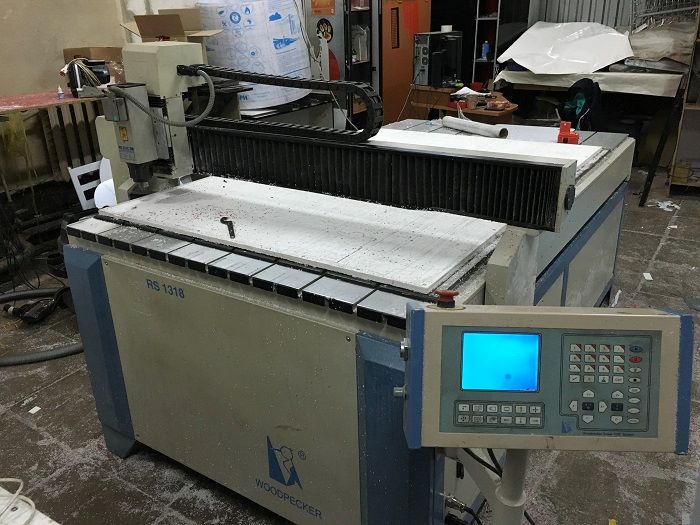
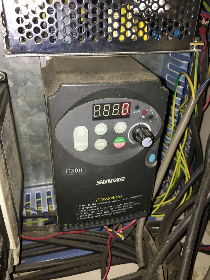

Woodpecker RS1318 сервопривод выдает ошибку
Началась эта история так… Я возвращался в офис после восстановления Woodpecker Camaro 2030. Времени было уже около 7-8 вечера, пробки как раз начинали рассасываться. Поступил звонок от оператора станка. Проблема была описана следующим образом…
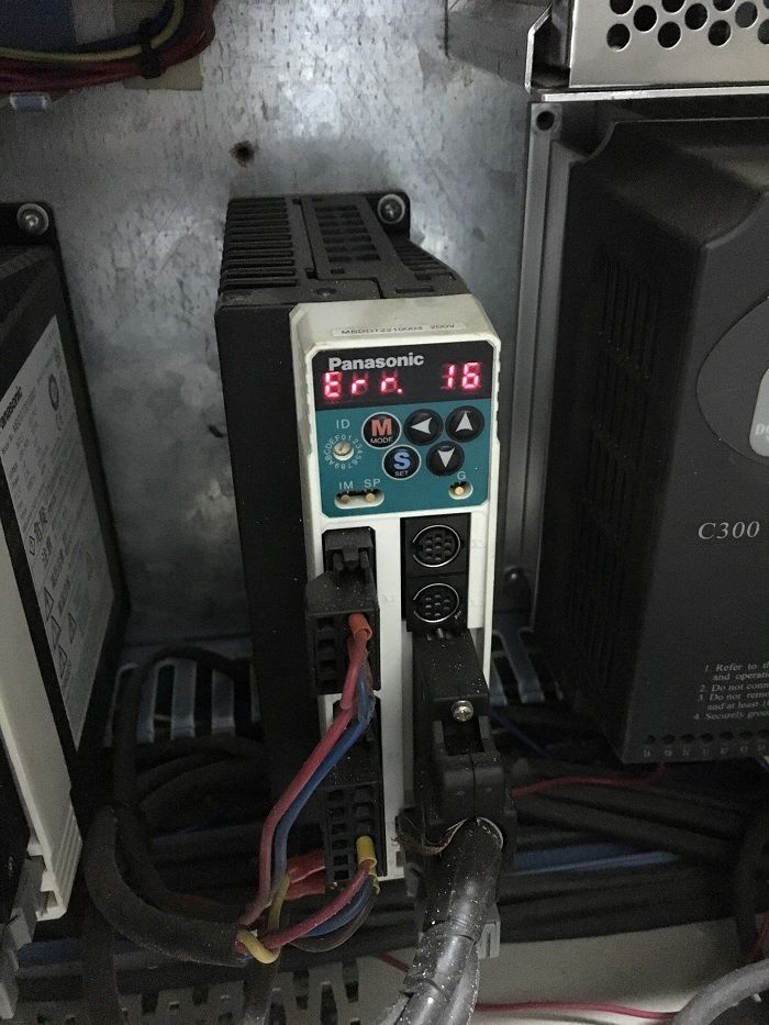
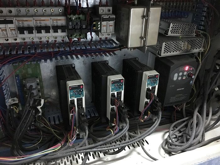
Станок Woodpecker RS1318 работал исправно на протяжении нескольких лет — как мне сказали 5-6 лет, за ним не ухаживали, не делали диагностику и смазку, да и убирали нерегулярно от раза к разу. В очередной рабочий день станок включили и он как обычно поехал в референтную точку дома для фиксации размеров рабочего поля. По осям X и Y станок исправно обнуляется, но при движении по оси Z происходил достаточной силы удар (стук) и станок уходил в аварийное состояние… Это состояние выводилось на экран драйвера panasonic в виде ошибки ERROR 16 — что значит превышение максимального усилия давления.
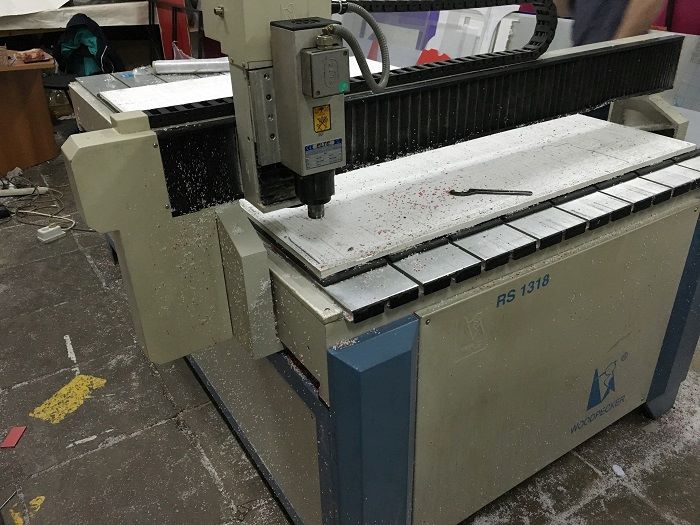
Я не стал терять времени и к 21-00 я уже был на месте. «Вскрытие показало» выход из строя датчика (концевого переключателя).
Время позднее, такие станки в Россию уже поставляются очень редко — оригинальный датчик найти не представлялось возможным.
Открылась «Волшебная сумка» и оттуда вынялся и припаялся Китайский индуктивный датчик OMRON, полностью совместимый с данным типом управления, и надеюсь проработает столько же).
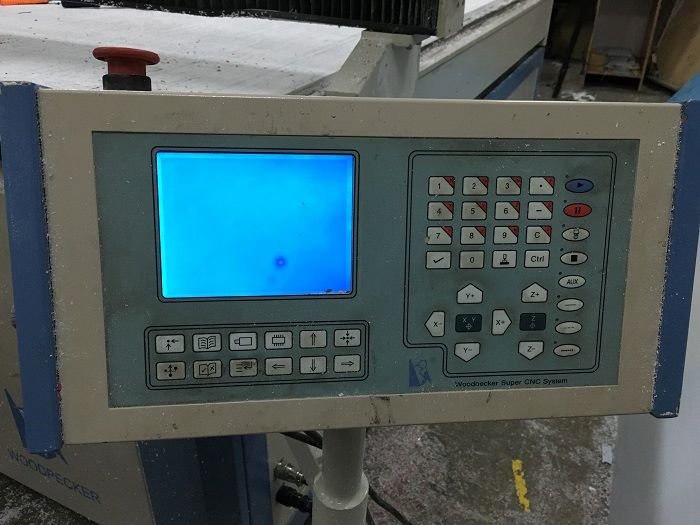
При диагностике выявилось, что дисплей на контроллере неисправен, теряет яркость и в ближайшее время совсем выйдет из строя, — а запчастей нет. Рекомендация — замена системы управления на NCStudio 5.5.60
В некотором будущем поменяем пару подшипников и думаю шпиндель (начал грется хоть и постоянно охлаждается).
SprutCAM Практик бесплатно на год при покупке станка с ЧПУ
Поделиться: