
7
Service
7.2
Error list
Code
Error
–
Communication
timeout
(motor stops, without
error code)
–
Supply voltage not
present
(motor stops, without
error code)
–
24 V supply not
present
(motor stops, without
error code)
01
Overcurrent in out-
put stage
04
Brake chopper
06
Phase failure
(The error can only
be detected when the
drive is under load)
64
Compact Operating Instructions – MOVIMOT
The following table helps you with troubleshooting:
Possible cause
Missing connection ‘, RS
+, RS- between
®
MOVIMOT
and RS485
master
EMC influence
Incorrect type (cyclical) for
acyclical data traffic, pro-
tocol period between the
individual messages is
longer than the set timeout
interval.
DC link voltage too low,
Power off has been detec-
ted.
24 V supply voltage not
present.
AUX power supply voltage
not available (only for
®
MOVIMOT
with AS-Inter-
face).
Short circuit on inverter
output
Overcurrent in brake out-
put, resistor damaged, res-
istance too low
Short circuit in brake coil
Phase failure
®
MM..D with AS-Interface
Measure
Check and establish connection, especially
ground.
Check shielding of data lines and improve, if
necessary.
Check the number of MOVIMOT
nected to the master. If the timeout interval is
1 s, for example, you can connect a maximum
®
of 8 MOVIMOT
drives as slaves for cyclical
communication.
Reduce message cycle, increase timeout in-
terval, or select message type «acyclic».
Check power cables and line voltage for inter-
ruption.
Check 24 V supply voltage for interruption.
Check 24 V supply voltage.
Permitted voltage: DC 24 V ± 25%,
EN 61131-2, residual ripple max. 13%
Motor restarts automatically as soon as the
voltage reaches normal values.
Check AUX power supply voltage for interrup-
tion.
Check AUX power supply voltage.
Permitted voltage: DC 24 V ± 25%,
EN 61131-2, residual ripple max. 13%
Motor restarts automatically as soon as the
voltage reaches normal values.
Check the connection between the inverter
output and the motor as well as the motor
winding for short circuits.
1)
Reset error.
Check the connection of the resistor/replace it.
Replace brake.
Check the supply system cable for phase fail-
ure.
1)
Reset error
.
®
drives con-
![]()
Drive Technology Drive Automation System Integration Services
Operating Instructions
MOVIMOT® MM..D
With DRS/DRE/DRP AC Motor
|
Edition 12/2010 |
17000017 / EN |
SEW-EURODRIVE—Driving the world

Contents
Contents
|
1 |
General Information ……………………………………………………………………………….. |
6 |
|
|
1.1 |
How to use this documentation…………………………………………………………. |
6 |
|
|
1.2 |
Structure of the safety notes …………………………………………………………….. |
6 |
|
|
1.3 |
Rights to claim under limited warranty ……………………………………………….. |
7 |
|
|
1.4 |
Exclusion of liability…………………………………………………………………………. |
7 |
|
|
1.5 |
Copyright……………………………………………………………………………………….. |
7 |
|
|
1.6 |
Product names and trademarks………………………………………………………… |
7 |
|
2 |
Safety Notes ………………………………………………………………………………………….. |
8 |
|
|
2.1 |
Preliminary information ……………………………………………………………………. |
8 |
|
|
2.2 |
General information ………………………………………………………………………… |
8 |
|
|
2.3 |
Target group ………………………………………………………………………………….. |
8 |
|
|
2.4 |
Designated use ………………………………………………………………………………. |
9 |
|
|
2.5 |
Other applicable documentation ……………………………………………………….. |
9 |
|
|
2.6 |
Transportation, storage………………………………………………………………….. |
10 |
|
|
2.7 |
Installation……………………………………………………………………………………. |
10 |
|
|
2.8 |
Electrical connection ……………………………………………………………………… |
10 |
|
|
2.9 |
Safe disconnection………………………………………………………………………… |
10 |
|
|
2.10 |
Operation …………………………………………………………………………………….. |
11 |
|
3 Unit Design ………………………………………………………………………………………….. |
12 |
|
|
3.1 |
MOVIMOT® drive………………………………………………………………………….. |
12 |
|
3.2 |
MOVIMOT® inverter………………………………………………………………………. |
13 |
|
3.3 |
Type designation of MOVIMOT® drive……………………………………………… |
15 |
|
3.4 |
Type designation of MOVIMOT® inverter …………………………………………. |
16 |
|
3.5 |
Type designation of the variant «mounted close to the motor»……………… |
17 |
|
4 Mechanical Installation…………………………………………………………………………. |
18 |
|
|
4.1 |
MOVIMOT® gearmotor installation ………………………………………………….. |
18 |
|
4.2 |
Installation of MOVIMOT® options …………………………………………………… |
20 |
|
4.3 |
Installation of the MOVIMOT® inverter close to the motor …………………… |
27 |
|
4.4 |
Tightening torques ………………………………………………………………………… |
28 |
|
5 Electrical Installation ……………………………………………………………………………. |
30 |
|
|
5.1 |
Installation instructions…………………………………………………………………… |
30 |
|
5.2 |
Connection of the MOVIMOT® drive………………………………………………… |
36 |
|
5.3 |
MOVIMOT® plug connectors ………………………………………………………….. |
37 |
5.4Connection between MOVIMOT® and motor
|
when mounted close to the motor……………………………………………………. |
38 |
|
|
5.5 |
Connection of the MOVIMOT® options ……………………………………………. |
42 |
|
5.6 |
Connection of RS-485 bus master…………………………………………………… |
53 |
|
5.7 |
Connecting the DBG keypad ………………………………………………………….. |
54 |
|
5.8 |
PC connection………………………………………………………………………………. |
55 |
|
Operating Instructions – MOVIMOT® MM..D with DRS/DRE/DRP AC Motor |
3 |
||

Contents
|
6 |
«Easy» Startup……………………………………………………………………………………… |
56 |
|
|
6.1 |
Overview ……………………………………………………………………………………… |
56 |
|
|
6.2 |
Important notes on startup ……………………………………………………………… |
57 |
|
|
6.3 |
Requirements……………………………………………………………………………….. |
58 |
|
|
6.4 |
Description of control elements……………………………………………………….. |
58 |
|
|
6.5 |
Description of the DIP switches S1………………………………………………….. |
61 |
|
|
6.6 |
Description of DIP switches S2……………………………………………………….. |
63 |
|
|
6.7 |
Selectable additional functions MM..D-503-00 ………………………………….. |
67 |
|
|
6.8 |
Startup with binary control ……………………………………………………………… |
91 |
|
|
6.9 |
Startup with options MBG11A or MLG..A …………………………………………. |
93 |
|
|
6.10 |
Startup with MWA21A option ………………………………………………………….. |
95 |
|
|
6.11 |
Startup with MWF11A option ………………………………………………………….. |
98 |
|
|
6.12 |
Supplementary notes for installation close to the motor …………………… |
100 |
|
7 |
«Easy» Startup with RS-485 Interface/Fieldbus…………………………………….. |
103 |
|
|
7.1 |
Important notes on startup ……………………………………………………………. |
103 |
|
|
7.2 |
Requirements……………………………………………………………………………… |
104 |
|
|
7.3 |
Startup procedure ……………………………………………………………………….. |
104 |
|
|
7.4 |
Coding of process data ………………………………………………………………… |
106 |
|
|
7.5 |
Function with RS-485 master………………………………………………………… |
111 |
|
8 |
«Expert» Startup with Parameter Function …………………………………………… |
116 |
|
|
8.1 |
Important notes on startup ……………………………………………………………. |
116 |
|
|
8.2 |
Requirements……………………………………………………………………………… |
117 |
|
|
8.3 |
MOVITOOLS® MotionStudio…………………………………………………………. |
117 |
|
|
8.4 |
Startup and function expansion with individual parameters……………….. |
119 |
|
|
8.5 |
Startup and configuration with a central controller and MQP……………… |
122 |
|
|
8.6 |
Startup by transferring the set of parameters ………………………………….. |
123 |
|
|
8.7 |
Parameter list……………………………………………………………………………… |
125 |
|
|
8.8 |
Parameter description………………………………………………………………….. |
131 |
|
9 Operation …………………………………………………………………………………………… |
151 |
|
|
9.1 |
Operating display ………………………………………………………………………… |
151 |
|
9.2 |
Drive ID module ………………………………………………………………………….. |
152 |
|
9.3 |
Keypads …………………………………………………………………………………….. |
153 |
|
9.4 |
MWA21A setpoint converter …………………………………………………………. |
154 |
|
9.5 |
MWF11A setpoint converter …………………………………………………………. |
155 |
|
9.6 |
MOVIMOT® manual operation with MOVITOOLS® MotionStudio ………. |
160 |
|
9.7 |
DBG keypad……………………………………………………………………………….. |
164 |
|
4 |
Operating Instructions – MOVIMOT® MM..D with DRS/DRE/DRP AC Motor |
||

Contents
|
10 Service ………………………………………………………………………………………………. |
172 |
|
|
10.1 |
Status and error display ……………………………………………………………….. |
172 |
|
10.2 |
Inspection/maintenance ……………………………………………………………….. |
176 |
|
10.3 |
Diagnostics with MWF11A option ………………………………………………….. |
177 |
|
10.4 |
Unit replacement…………………………………………………………………………. |
178 |
|
10.5 |
Rotating the connection box …………………………………………………………. |
180 |
|
10.6 |
SEW Service………………………………………………………………………………. |
182 |
|
10.7 |
Shut down ………………………………………………………………………………….. |
182 |
|
10.8 |
Storage ……………………………………………………………………………………… |
183 |
|
10.9 |
Extended storage………………………………………………………………………… |
183 |
|
10.10 |
Disposal …………………………………………………………………………………….. |
183 |
|
11 |
Technical Data……………………………………………………………………………………. |
184 |
|
|
11.1 |
Motor with operating point 400 V / 50 Hz or 400 V / 100 Hz………………. |
184 |
|
|
11.2 |
Motor with operating point 460 V / 60 Hz………………………………………… |
186 |
|
|
11.3 |
Motor with operating point 230 V / 60 Hz………………………………………… |
188 |
|
|
11.4 |
Technical data of options & accessories…………………………………………. |
190 |
|
|
11.5 |
Work done, working air gap and braking torque of the brake …………….. |
195 |
|
|
11.6 |
Braking torque assignment …………………………………………………………… |
195 |
|
|
11.7 |
Integrated RS-485 interface………………………………………………………….. |
196 |
|
|
11.8 |
Diagnostics interface……………………………………………………………………. |
196 |
|
|
11.9 |
Assignment of internal braking resistors …………………………………………. |
196 |
|
|
11.10 |
Assignment of external braking resistors ………………………………………… |
197 |
|
|
11.11 |
Resistance and assignment of the brake coil ………………………………….. |
197 |
|
|
11.12 |
Assignment of the Drive-ID module ……………………………………………….. |
198 |
|
|
12 |
Declaration of Conformity …………………………………………………………………… |
199 |
|
|
13 |
Address List ………………………………………………………………………………………. |
200 |
|
|
Index |
………………………………………………………………………………………………….. |
210 |
|
Operating Instructions – MOVIMOT® MM..D with DRS/DRE/DRP AC Motor |
5 |
||
General Information
How to use this documentation
1 General Information
1.1How to use this documentation
The documentation is an integral part of the product and contains important information on operation and service. The documentation is written for all employees who assemble, install, startup, and service this product.
The documentation must be accessible and legible. Make sure that persons responsible for the system and its operation, as well as persons who work independently on the unit, have read through the documentation carefully and understood it. If you are unclear about any of the information in this documentation, or if you require further information, contact SEW-EURODRIVE.
1.2Structure of the safety notes
1.2.1Meaning of the signal words
The following table shows the grading and meaning of the signal words for safety notes, notes on potential risks of damage to property, and other notes.
|
Signal word |
Meaning |
Consequences if disregarded |
|
DANGER |
Imminent danger |
Severe or fatal injuries |
|
WARNING |
Possible dangerous situation |
Severe or fatal injuries |
|
CAUTION |
Possible dangerous situation |
Minor injuries |
|
NOTICE |
Possible damage to property |
Damage to the drive system or its envi- |
|
ronment |
||
|
INFORMATION |
Useful information or tip: Simpli- |
|
|
fies the handling of the drive |
||
|
system. |
||
1.2.2Structure of the section-related safety notes
Section safety notes do not apply to a specific action, but to several actions pertaining to one subject. The used symbols indicate either a general or a specific hazard.
This is the formal structure of a section safety note:
SIGNAL WORD
Type and source of danger.
Possible consequence(s) if disregarded.
•Measure(s) to prevent the danger.
1.2.3Structure of the embedded safety notes
Embedded safety notes are directly integrated in the instructions just before the description of the dangerous action.
This is the formal structure of an embedded safety note:
• SIGNAL WORD Nature and source of hazard. Possible consequence(s) if disregarded.
– Measure(s) to prevent the danger.
Operating Instructions – MOVIMOT® MM..D with DRS/DRE/DRP AC Motor

|
General Information |
1 |
|
Rights to claim under limited warranty |
||
1.3Rights to claim under limited warranty
A requirement of fault-free operation and fulfillment of any rights to claim under limited warranty is that you adhere to the information in the documentation. Read the documentation before you start working with the unit!
1.4Exclusion of liability
You must comply with the information contained in this documentation to ensure safe operation of MOVIMOT® and to achieve the specified product characteristics and performance features. SEW-EURODRIVE assumes no liability for injury to persons or damage to equipment or property resulting from non-observance of these operating instructions. In such cases, any liability for defects is excluded.
1.5Copyright
© 2010 – SEW-EURODRIVE. All rights reserved.
Unauthorized duplication, modification, distribution or any other use of the whole or any part of this documentation is strictly prohibited.
1.6Product names and trademarks
All brands and product names in this documentation are trademarks or registered trademarks of their respective titleholders.
|
Operating Instructions – MOVIMOT® MM..D with DRS/DRE/DRP AC Motor |
7 |
||

|
2 |
Safety Notes |
|
Preliminary information |
||
2 Safety Notes
The following basic safety notes must be read carefully to prevent injury to persons and damage to property. The operator must ensure that the basic safety notes are read and adhered to. Make sure that persons responsible for the plant and its operation, as well as persons who work independently on the unit, have read through the operating instructions carefully and understood them. If you are unclear about any of the information in this documentation or if you require further information, please contact SEWEURODRIVE.
2.1Preliminary information
The following safety notes are primarily concerned with the use of MOVIMOT® drives. If you use other SEW components, also refer to the safety notes for the respective components in the corresponding documentation.
Please also observe the supplementary safety notes in the individual chapters of this documentation.
2.2General information
Never install or start up damaged products. Submit a complaint to the shipping company immediately in the event of damage.
During operation, MOVIMOT® drives can have live, bare and movable or rotating parts as well as hot surfaces, depending on their enclosure.
Removing covers without authorization, improper use as well as incorrect installation or operation may result in severe injuries to persons or damage to property. Refer to the documentation for additional information.
2.3Target group
Only qualified personnel is authorized to install, startup or service the units or correct unit faults (observing IEC 60364 and/or CENELEC HD 384 or DIN VDE 0100 and IEC 60664 or DIN VDE 0110 as well as national accident prevention guidelines).
Qualified personnel in the context of these basic safety notes are persons familiar with installation, assembly, startup and operation of the product who possess the necessary qualifications.
Any activities regarding transportation, storage, operation, and disposal must be carried out by persons who have been instructed appropriately.
|
8 |
Operating Instructions – MOVIMOT® MM..D with DRS/DRE/DRP AC Motor |
||

|
Safety Notes |
2 |
|
Designated use |
||
2.4Designated use
MOVIMOT® inverters are components intended for installation in electrical systems or machines.
In case of installation in machines, startup of MOVIMOT® inverters (i.e. start of designated operation) is prohibited until it is determined that the machine meets the requirements stipulated in the Machinery Directive 2006/42/EC.
Startup (i.e. the start of designated use) is only permitted under observance of the EMC directive 2004/108/EC.
MOVIMOT® inverters comply with the regulations of the Low Voltage Directive 2006/95/ EC. The standards given in the declaration of conformity are used for the MOVIMOT® inverter.
You must observe the technical data and information on the connection requirements as provided on the nameplate and in the documentation.
2.4.1Safety functions
The MOVIMOT® inverter may not perform safety functions unless these functions are described and expressly permitted.
2.4.2Hoist applications
MOVIMOT® inverters are suitable for hoist applications to a limited degree only, see sec. «Additional function 9» (page 78).
MOVIMOT® inverters are not designed for use as a safety device in hoist applications.
2.5Other applicable documentation
Note also the following documentation:
•«MOVIMOT® Gearmotors» catalog
•«DR.71-225, 315 AC Motors» operating instructions
•Operating instructions for the gear unit (only for MOVIMOT® gearmotors)
You can download or order these publications on the Internet (http://www.sew-euro- drive.de, under the heading «Documentation»).
|
Operating Instructions – MOVIMOT® MM..D with DRS/DRE/DRP AC Motor |
9 |
||

|
2 |
Safety Notes |
|
Transportation, storage |
||
2.6Transportation, storage
You must observe the notes on transportation, storage and proper handling. Comply with the requirements for climatic conditions stated in chapter «Technical Data». Tighten installed eyebolts securely. They are designed for the weight of the MOVIMOT® drive. Do not attach any additional loads. Use suitable, sufficiently rated handling equipment (e.g. rope guides) if required.
2.7Installation
The units must be installed and cooled according to the regulations and specifications in the corresponding documentation.
Protect the MOVIMOT® inverters from improper strain.
The following applications are prohibited unless the unit is explicitly designed for such use:
•Use in potentially explosive atmospheres.
•Use in areas exposed to harmful oils, acids, gases, vapors, dust, radiation, etc.
•Use in non-stationary applications with strong mechanical oscillation and impact loads; see chapter «Technical Data».
2.8Electrical connection
Observe the applicable national accident prevention guidelines when working on live MOVIMOT® drive inverters (e.g. BGV A3).
Perform electrical installation according to the pertinent regulations (e.g. cable cross sections, fusing, protective conductor connection). For any additional information, refer to the applicable documentation.
For notes on EMC compliant installation, such as shielding, grounding, arrangement of filters and routing of lines, refer to chapter «Installation instructions». The manufacturer of the system or machine is responsible for maintaining the limits established by EMC legislation.
Protective measures and protection devices must comply with the regulations in force (e.g. EN 60204 or EN 61800-5-1).
A voltage test according to EN 61800-5-1:2007 chapter 5.2.3.2 is required for the MOVIMOT® drives prior to startup in order to ensure the insulation.
2.9Safe disconnection
MOVIMOT® inverters meet all requirements for safe disconnection of power and electronic connections in accordance with EN 61800-5-1. All connected circuits must also satisfy the requirements for safe disconnection.
|
10 |
Operating Instructions – MOVIMOT® MM..D with DRS/DRE/DRP AC Motor |
||
![]()
Safety Notes
Operation
2.10Operation
Systems with integrated MOVIMOT® inverters must be equipped with additional monitoring and protection devices according to the applicable safety guidelines, such as the law governing technical equipment, accident prevention regulations, etc. Additional protective measures may be necessary for applications with increased potential risk.
Do not touch live components and power connections immediately after separation of the MOVIMOT® inverter from the supply voltage because there may still be some charged capacitors. Wait at least for 1 minute after having switched off the supply voltage.
As soon as supply voltages are present at the MOVIMOT® inverter, the connection box must be closed (i.e. the MOVIMOT® inverter and, if applicable, the connector of the hybrid cable must be connected).
The fact that the status LED and other display elements are no longer illuminated does not indicate that the unit has been disconnected from the supply system and no longer carries any voltage.
Mechanical blocking or internal safety functions of the unit can cause a motor standstill. Eliminating the cause of the problem or performing a reset may result in the drive restarting automatically. If, for safety reasons, this is not permitted for the driven machine, disconnect the unit from the supply system before correcting the error.
Caution: Danger of burns: The surface temperature of the MOVIMOT® drive and of external options, e.g. the heat sink of the braking resistor, can exceed 60 °C during operation!
Operating Instructions – MOVIMOT® MM..D with DRS/DRE/DRP AC Motor
|
3 |
Unit Design |
MOVIMOT® drive |
3 Unit Design
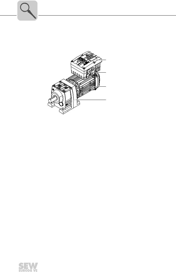
3.1MOVIMOT® drive
The following figure shows a MOVIMOT® drive with helical gear unit:
[1]
[2]
[3]
[4]
3531634827
[1]MOVIMOT® inverter
[2]Connection box
[3]Motor
[4]Helical gear unit
A MOVIMOT® drive is a combination of:
•MOVIMOT® inverter
–Mounted on the motor (see example above)
–or mounted close to the motor
•Motor (see motor operating instructions)
•Gear unit (optional, see gear unit operating instructions)
|
12 |
Operating Instructions – MOVIMOT® MM..D with DRS/DRE/DRP AC Motor |
||
|
Unit Design |
3 |
MOVIMOT® inverter |
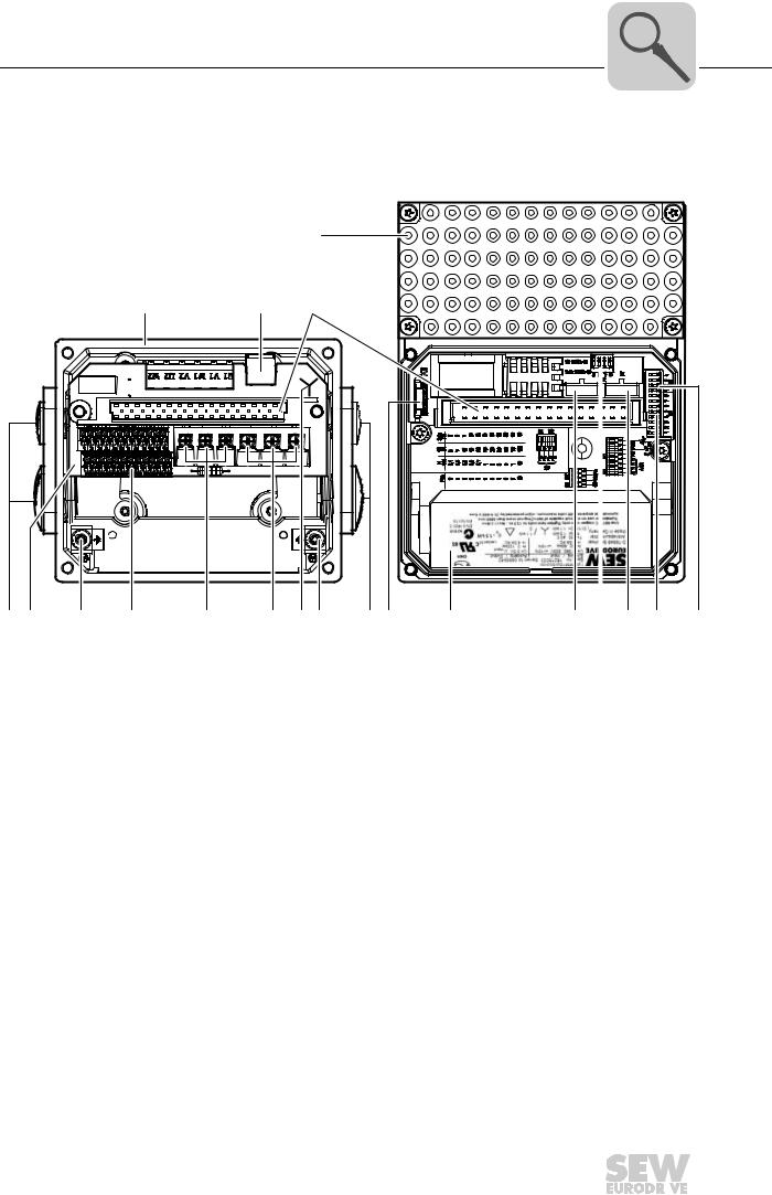
3.2MOVIMOT® inverter
The following figure shows the connection box and the MOVIMOT® inverter:
|
[5] |
[6] |
[7] |
[8] |
[9] |
[10] |
[11] [7] |
|
0 1 2 |
0 1 2 |
|||||
|
[5] [12] |
[13] |
[14] |
[15] |
[16] |
[17] |
[18] |
|
615683595 |
[1]Connection box
[2]X10: Plug connector for BEM option
[3]Plug connector for MOVIMOT® inverter
[4]MOVIMOT® inverter with heat sink
[5]Cable glands
[6]Connection unit with terminals
[7]Screw for PE connection
[8]X5, X6: Electronics terminal strips
[9]X1: Connection for brake coil (motors with brake) or braking resistor (motors without brake)
[10]X1: Supply system connection L1, L2, L3
[11]Connection type identification
[12]Drive-ID module
[13]Nameplate of the MOVIMOT® inverter
[14]Setpoint switch f2 (green)
[15]DIP switches S2/5 – S2/8
[16]Switch t1 for integrator ramp (white)
[17]DIP switches S1/1 – S1/8
[18]DIP switches S2/1 – S2/4
|
Operating Instructions – MOVIMOT® MM..D with DRS/DRE/DRP AC Motor |
13 |
||

|
3 |
Unit Design |
|
MOVIMOT® inverter |
The following figure shows the top of the MOVIMOT® inverter:
[1]X50: Diagnostics interface with screw plug
[2]Setpoint potentiometer f1 with screw plug
[3]Status LED
[4]Unit identification
|
14 |
Operating Instructions – MOVIMOT® MM..D with DRS/DRE/DRP AC Motor |
||
|
Unit Design |
3 |
Type designation of MOVIMOT® drive |
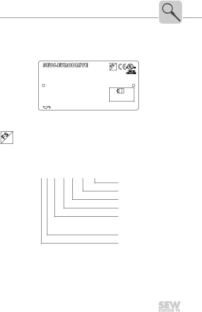
3.3Type designation of MOVIMOT® drive
3.3.1Nameplate
The following figure gives an example of a nameplate of a MOVIMOT® drive. The nameplate is attached to the motor.
|
76646 Bruchsal/Germany |
01 |
|||||||||
|
RF47DRE90L4BE2/MM15/MO |
||||||||||
|
01.300123457.0002.06 |
°C |
-20…40 |
||||||||
|
V |
380-500 |
Hz 50-60 |
A |
3.5 |
Iso.Kl. |
155(F) |
||||
|
kW |
1.5 |
Hz |
50 |
r/min |
1400/86 |
CT |
1:5 |
TEFC |
||
|
I |
16.22 |
Nm |
166 |
IP |
54 |
M.L. |
02 |
3~ |
||
|
IM |
M1 |
kg |
31 |
|||||||
|
V BR |
220..240 |
Nm |
13 |
kW |
1.5 |
Hz 50 |
||||
|
eff % |
85.2 |
|||||||||
|
1883410 |
||||||||||
|
CLP CC VGB220 0.65I |
Made in Germany |
9007199774918155
The logos at the top of the nameplate are only there if:
•the motor is manufactured accordingly,
•and contains at least one safety-rated component.
The FS logo on the nameplate is based on the combination of safety-related components that is installed.
3.3.2Type designation
The following table shows the type designation of the MOVIMOT® drive:
RF 47 DRE 90L4 BE/MM15/MO
Additional feature: inverter 1)
MOVIMOT® inverter
Optional design motor (brake)
Size, number of poles on motor
Motor series
DRS = DRS motor
DRE = DRE motor
DRP = DRP motor
Gear unit size
Gear unit series
1) The nameplate only displays options installed at the factory.
The available variants are listed in the «MOVIMOT® Gearmotors» catalog.
|
Operating Instructions – MOVIMOT® MM..D with DRS/DRE/DRP AC Motor |
15 |
||
|
3 |
Unit Design |
Type designation of MOVIMOT® inverter |
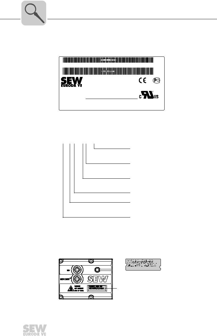
3.4Type designation of MOVIMOT® inverter
3.4.1Nameplate
The following figure gives an example of a nameplate of a MOVIMOT® inverter:
|
Status: |
10 |
12 |
— A — — |
10 |
10 |
12 |
02 / 08 444 |
|||||||
|
Type : MM15D-503-00 |
||||||||||||||
|
P# : |
18215033 |
S# : 0886946 |
||||||||||||
|
Eingang / |
Input |
Ausgang / Output |
CH01 |
|||||||||||
|
U = |
3×380 . . . 500V AC |
U = |
3x0V . . . Uin |
|||||||||||
|
D-76646 Bruchsal |
I |
= |
3.5A AC |
I |
= |
4.0A AC |
N2936 |
|||||||
|
Made in Germany |
f |
= |
50 … 60Hz |
f |
= |
2 … 120Hz |
||||||||
|
MOVIMOT |
T = |
-30 . . . +40°C |
||||||||||||
|
Antriebsumrichter |
P-Motor |
1.5kW / 2.0HP |
||||||||||||
|
Drive Inverter |
Use 60/75°C copper wire only. Tighten terminals to 13.3 in.– ibs. (1.5 Nm). Suitable for use on a circuit capable of delivering not more than 200,000 rms symmetrical amperes, 500 volts maximum. Integral solid state short crcuit protection does not provide BCP. BCP must be provided in
accordance with the NEC and any additional local codes.
9007201212668299
3.4.2Type designation
The following table shows the type designation of the MOVIMOT® inverter:
MM 15 D – 503 – 00
Variant
00 = Standard
Connection type
3 = 3-phase
Supply voltage
50 = AC 380 – 500 V
23 = AC 200 – 240 V
Version D
Motor power
15 = 1.5 kW
Unit series
MM = MOVIMOT®
The available variants are listed in the «MOVIMOT® Gearmotors» catalog.
3.4.3Unit identification
The unit identification [1] on the top of the MOVIMOT® inverter provides information about the inverter type [2], inverter part number [3], unit power [4].
[2] 


 [3]
[3] 


 [4]
[4]
[1]
457916555
|
16 |
Operating Instructions – MOVIMOT® MM..D with DRS/DRE/DRP AC Motor |
||
Unit Design
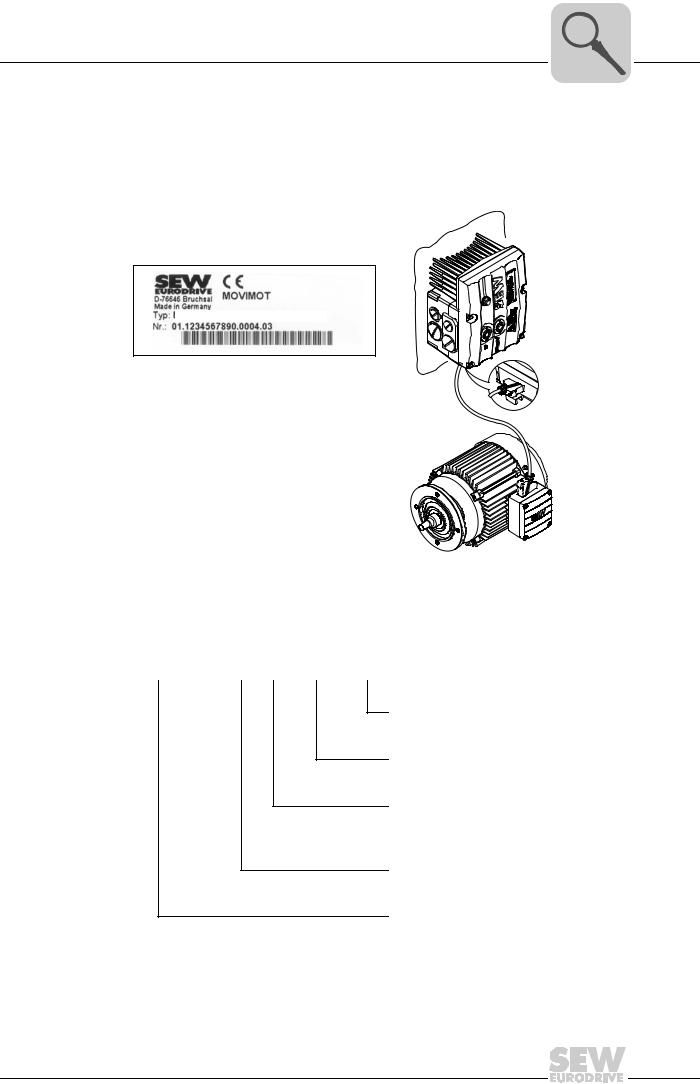
Type designation of the variant «mounted close to the motor»
3.5Type designation of the variant «mounted close to the motor»
3.5.1Nameplate
The following illustration shows an example of the MOVIMOT® inverter mounted close to the motor with corresponding nameplate:
MM15D-503-00/0/P21A/RO1A/APG4
457921547
3.5.2Type designation
The following table shows the type designation of a MOVIMOT® inverter mounted close to the motor:
MM15D-503-00/0/P21A/RO1A/APG4
Plug connector
For the connection to the motor
Connection box design
Adapter for mounting close to the motor
21 = Size 1
22 = Size 2
Connection type
MOVIMOT® inverter
Operating Instructions – MOVIMOT® MM..D with DRS/DRE/DRP AC Motor

|
4 |
Mechanical Installation |
MOVIMOT® gearmotor installation |
4 Mechanical Installation
4.1MOVIMOT® gearmotor installation
4.1.1General information
•Observe the general safety notes.
•Strictly observe all instructions as to the technical data and the permissible conditions regarding the place of installation.
•Only use the provided attachment options when mounting the MOVIMOT® drive.
•Only use mounting and locking elements that fit into the existing bores, threads and countersinks.
4.1.2Installation requirements
Make sure that the following requirements are met before you start installing the unit:
•The data on the nameplate of the drive matches the voltage supply system.
•The drive is undamaged (no damage caused by transportation or storage)
•The ambient temperature corresponds to the specifications in chapter «Technical Data». Note that the temperature range of the gear unit may also be restricted (see gear unit operating instructions).
•The MOVIMOT® drive must not be installed under the following harmful ambient conditions:
–Potentially explosive atmospheres
–Oils
–Acids
–Gases
–Vapors
–Radiation
–etc.
•When the drive is installed in abrasive ambient conditions, protect the output end oil seals against wear.
|
Installation toler- |
The following tables shows the permitted tolerances of the shaft ends and flanges of the |
|
|
ances |
MOVIMOT® drive. |
|
|
Shaft end |
Flanges |
|
|
Diameter tolerance according to EN 50347 |
Centering shoulder tolerance in accordance |
|
|
• ISO j6 with Ø ≤ 26 mm |
with EN 50347 |
|
|
• ISO k6 with Ø ≤ 38 mm up to ≤ 48 mm |
• ISO j6 with Ø ≤ 250 mm |
|
|
• ISO m6 at Ø > 55 mm |
• ISO h6 with Ø > 300 mm |
|
|
• Center bore in accordance with DIN 332, |
||
|
shape DR.. |
|
18 |
Operating Instructions – MOVIMOT® MM..D with DRS/DRE/DRP AC Motor |
||

|
Mechanical Installation |
4 |
|
MOVIMOT® gearmotor installation |
4.1.3Installing MOVIMOT®
NOTICE
Loss of warranted degree of protection if the MOVIMOT® inverter is installed incorrectly or not at all.
Damage to the MOVIMOT® inverter.
•If you remove the MOVIMOT® inverter from the connection box, you must protect it from moisture and dust.
Observe the following notes for mounting the MOVIMOT® drive:
•Only install the MOVIMOT® drive on a level, low-vibration, and torsionally rigid support structure.
•Observe the mounting position specified on the motor nameplate.
•Thoroughly remove any anti-corrosion agent from the shaft end. Use a commercially available solvent. Do not allow the solvent to penetrate the bearings and shaft seals
– this could damage the material.
•Align the motor carefully to avoid placing any unacceptable strain on the motor shafts. Observe the permitted overhung and axial loads specified in the «MOVIMOT® Gearmotors» catalog.
•Do not jolt or hammer the shaft end.
•Use an appropriate cover to prevent objects or fluids from entering motors in vertical mounting positions.
•Ensure sufficient clearance around the unit to allow for adequate cooling. Avoid the drawing in of warm outlet air of other units.
•Balance components that were subsequent mounted to the shaft with a half key (output shafts are balanced with a half key).
•Existing condensation drain holes are sealed with plastic plugs. Only open them, if necessary.
Open condensation drain holes are not permitted. If condensation drain holes are open, higher enclosures are no longer possible.
4.1.4Installation in damp locations or in the open
Observe the following notes for mounting the MOVIMOT® drive in damp areas or in the open:
•Use suitable cable glands for the cables. Use reducing adapters, if necessary.
•Coat the threads of the cable glands and filler plugs with sealing compound and tighten them properly. Then coat the cable glands again.
•Seal the cable entries properly.
•Clean the sealing faces of the MOVIMOT® inverter well before re-assembly.
•If the corrosion protection coating is damaged, restore the coating.
•Check whether the degree of protection specified on the nameplate is permitted in the ambient conditions on site.
|
Operating Instructions – MOVIMOT® MM..D with DRS/DRE/DRP AC Motor |
19 |
||
|
4 |
Mechanical Installation |
Installation of MOVIMOT® options |
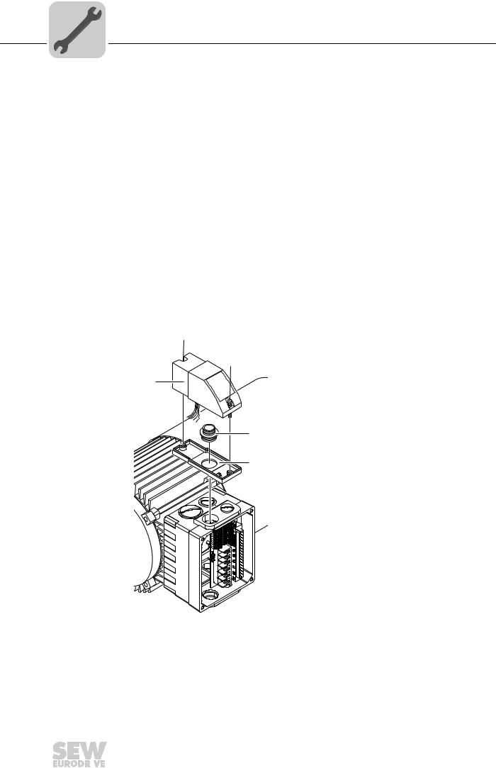
4.2Installation of MOVIMOT® options
4.2.1MLU11A / MLU21A / MLG..A option
|
Scope of delivery |
• MLU11A / MLU21A / MLG..A upper part [2] |
•2 screws [1]
•Transit bolt [4]
•MLU11A / MLU21A / MLG..A lower part [5]
|
Installation |
1. Remove a screw plug on the MOVIMOT® connection box. |
2.Fix the lower part [5] on the MOVIMOT® connection box and fasten it with a transit bolt [4] (tightening torque 2.5 Nm / 22 lb.in).
3.Route the connection cable [3] through the transit bolt [4] into the inside of the MOVIMOT® connection box.
4.Fit the upper part [2] onto the lower part [5] and fasten it with two screws [1] (tightening torque 0.9 – 1.1 Nm / 8 – 10 lb.in).
Mount the option in the following position only:
[1]
[1]
[2]
[3] 
458285835
For more information about connecting the MLU11A/MLU21A option, refer to sec. «Connection of option MLU11A/MLU21A» (page 42).
For more information about connecting the MLG..A option, refer to sec. «Connection of option MLG..A» (page 43).
|
20 |
Operating Instructions – MOVIMOT® MM..D with DRS/DRE/DRP AC Motor |
||
![]()
Mechanical Installation
Installation of MOVIMOT® options
4.2.2MLU13A option
Option MLU13A is installed in the modular connection box at the factory. If you have any questions about retrofitting the option, please contact the SEW-EURODRIVE service.
INFORMATION
Only install this option in combination with the modular connection box of MOVIMOT® MM03D-503-00 – MM40D-503-00.
The following figure depicts an installation example. The installation depends on the used connection box and on other installed options, if there are any.
1113300875
For more information about connecting the MLU13A option, refer to chapter «Connection of option MLU13A» (page 42).
Operating Instructions – MOVIMOT® MM..D with DRS/DRE/DRP AC Motor
Mechanical Installation
Installation of MOVIMOT® options
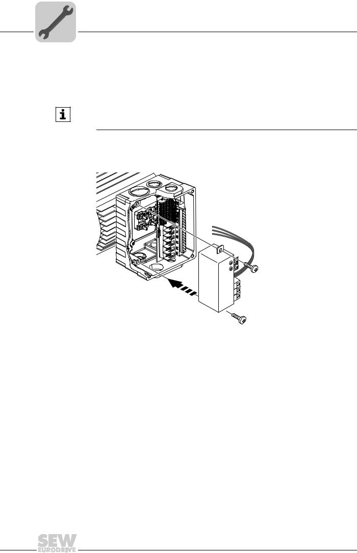
4.2.3MNF21A option
Option MNF21A is installed in the modular connection box at the factory. If you have any questions about retrofitting the option, please contact the SEW-EURODRIVE service.
INFORMATION
Only install this option in combination with the modular connection box of MOVIMOT® MM03D-503-00 – MM15D-503-00.
The following figure depicts an installation example. The installation depends on the used connection box and on other installed options, if there are any.
2753184651
For more information about connecting the MNF21A option, refer to chapter «Connecting the MNF21A option» (page 44).
Operating Instructions – MOVIMOT® MM..D with DRS/DRE/DRP AC Motor

Mechanical Installation
Installation of MOVIMOT® options
4.2.4URM/BEM/BES options
The URM, BEM and BES options are installed in the connection box at the factory. If you have any questions about retrofitting the options URM, BEM, or BES, please contact the SEW-EURODRIVE service.
The following figure depicts an installation example. The installation depends on the used connection box and on other installed options, if there are any.
458307467
For more information about connecting the URM option, refer to chapter «Connection of option URM» (page 45).
For more information about connecting the BEM option, refer to chapter «Connection of option BEM» (page 46).
For more information about connecting the BES option, refer to chapter «Connection of option BES» (page 47).
Operating Instructions – MOVIMOT® MM..D with DRS/DRE/DRP AC Motor
|
4 |
Mechanical Installation |
|
Installation of MOVIMOT® options |
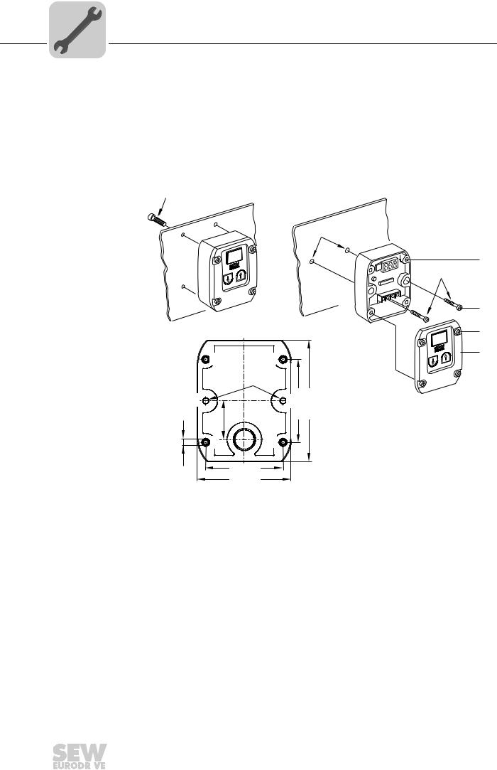
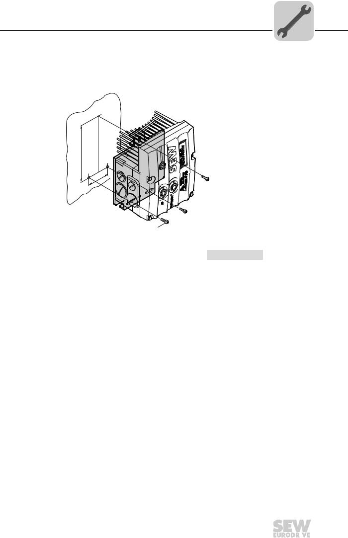
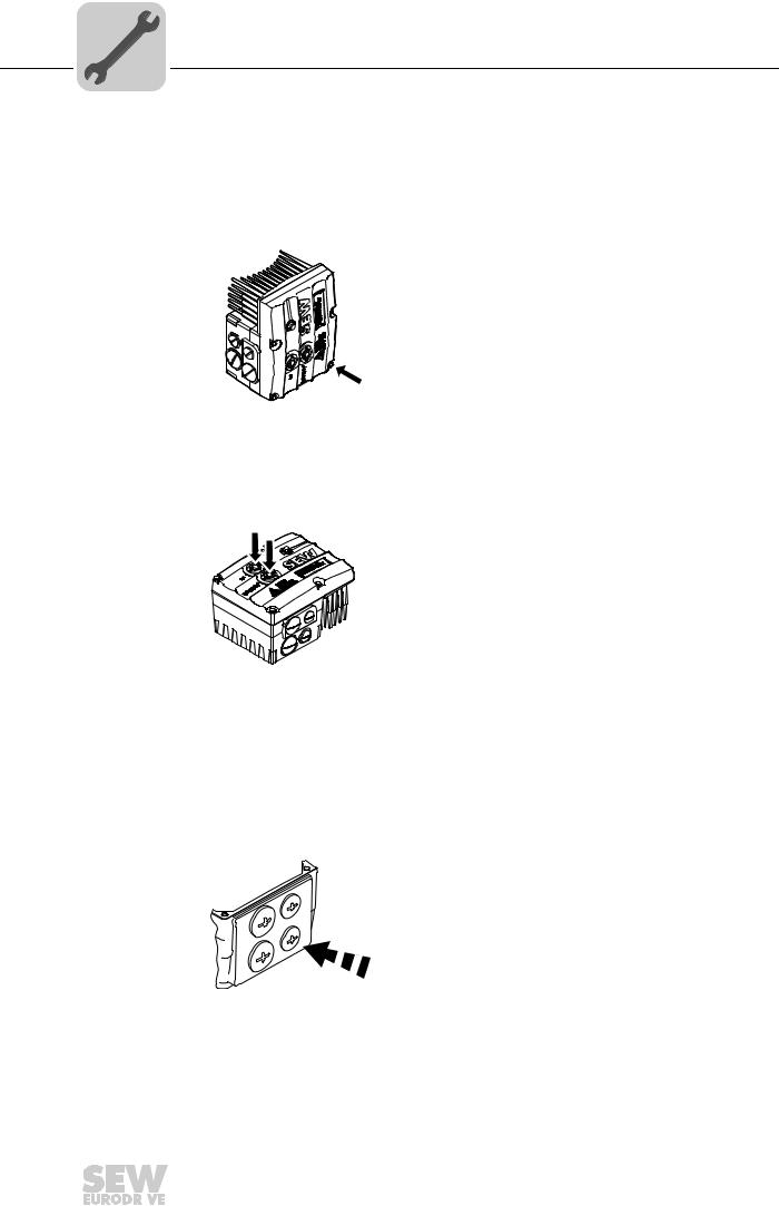
4.2.5Installation MBG11A
There are two ways to mount option MBG11A to a wall:
A:Mounting from the rear using 4 tapped holes.
(Tightening torque of retaining screw [1]: 1.6 – 2.0 Nm / 14 – 18 lb.in)
B:Mounting from the front using 2 retaining holes
(Tightening torque of retaining screw [3]: 1.6 – 2.0 Nm / 14 – 18 lb.in)
|
A |
A |
|
|
Ø 4,3 mm |
||
|
B |
Bmm |
<![if ! IE]>
<![endif]>mm |
| <![if ! IE]>
<![endif]>mm |
<![if ! IE]>
<![endif]>60 |
<![if ! IE]>
<![endif]>88 |
| <![if ! IE]>
<![endif]>28 |
||
|
A |
A |
|
| <![if ! IE]>
<![endif]>M4 |
56 mm |
|
|
68 mm |
a = Wall thickness
Screws are not included in the scope of delivery.
[2]
M4 x 25
[3]
[4]
[5]
322404747
Fit the upper part [5] onto the lower part [2] and fasten it with two screws [4] (tightening torque 0.3 Nm / 2.6 lb.in).
For more information about connecting the MBG11A option, refer to sec. «Connection of option MBG11A» (page 48).
|
24 |
Operating Instructions – MOVIMOT® MM..D with DRS/DRE/DRP AC Motor |
||
|
Mechanical Installation |
4 |
|
Installation of MOVIMOT® options |
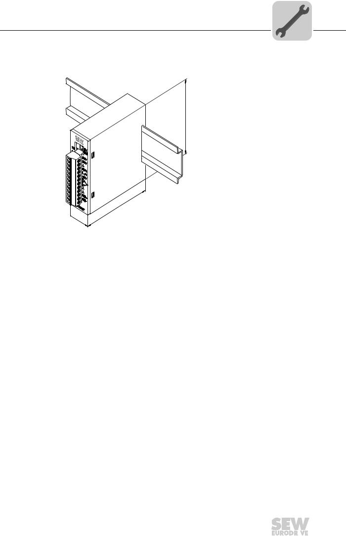
4.2.6MWA21A option
Install option MWA21A in the control cabinet on a mounting rail according to EN 50022:
<![if ! IE]>
<![endif]>75
74
 22,5
22,5
322411915
For more information about connecting the MWA21A option, refer to sec. «Connection of option MWA21A» (page 49).
|
Operating Instructions – MOVIMOT® MM..D with DRS/DRE/DRP AC Motor |
25 |
||
|
4 |
Mechanical Installation |
|
Installation of MOVIMOT® options |
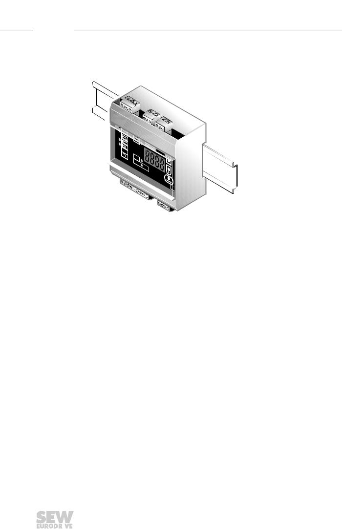
4.2.7MWF11A option
Install option MWF11A in the control cabinet on a mounting rail according to EN 50022:
100
<![if ! IE]>
<![endif]>75
52
3180221579
For more information about connecting the MWF11A option, refer to chapter «Connection of option MWF11A» (page 50).
|
26 |
Operating Instructions – MOVIMOT® MM..D with DRS/DRE/DRP AC Motor |
||
|
Mechanical Installation |
4 |
Installation of the MOVIMOT® inverter close to the motor |
4.3Installation of the MOVIMOT® inverter close to the motor
The following figure shows the mounting dimensions for installing the MOVIMOT® inverter close to the motor:
 M6
M6
<![if ! IE]>
<![endif]>A
B
|
M6 |
||||
|
458277771 |
||||
|
Size |
Type |
A |
B |
|
|
1 |
MM03D503-00 – MM15D-503-00 |
140 mm |
65 mm |
|
|
MM03D233-00 – MM07D-233-00 |
||||
|
2 / 2L |
MM22D503-00 – MM40D-503-00 |
170 mm |
65 mm |
|
|
MM11D233-00 – MM22D-233-00 |
||||
|
Operating Instructions – MOVIMOT® MM..D with DRS/DRE/DRP AC Motor |
27 |
||
|
4 |
Mechanical Installation |
|
Tightening torques |
||
4.4Tightening torques
4.4.1MOVIMOT® inverter
Tighten the screws on the MOVIMOT® inverter using 3.0 Nm (27 lb.in) working diagonally across.
458577931
4.4.2Screw plugs
Tighten screw plugs of potentiometer f1 and connection X50 using 2.5 Nm (22 lb.in).
458570379
4.4.3Cable glands
It is essential to observe the manufacturer’s specifications for the cable glands.
4.4.4Blanking plug cable entries
Tighten blanking plug screws with 2.5 Nm (22 lb.in).
322777611
|
28 |
Operating Instructions – MOVIMOT® MM..D with DRS/DRE/DRP AC Motor |
||

|
Mechanical Installation |
4 |
|
|
Tightening torques |
||
4.4.5Modular connection box
For fastening the connection box on the mounting plate, tighten screws using 3.3 Nm (29 lb.in).
322786187
4.4.6Tightening torques for terminals
Use the following tightening torques for terminals during installation:
458605067
[1]0.8 – 1.5 Nm (7 – 13 lb.in)
[2]1.2 – 1.6 Nm (11 – 14 lb.in)
[3]2.0 – 2.4 Nm (18 – 21 lb.in)
|
Operating Instructions – MOVIMOT® MM..D with DRS/DRE/DRP AC Motor |
29 |
||

|
5 |
Electrical Installation |
|
Installation instructions |
||
5 Electrical Installation
5.1Installation instructions
5.1.1Supply system connection
•The rated voltage and frequency of the MOVIMOT® inverter must correspond to the data for the power supply system.
•Install line fuses at the beginning of the power supply cable behind the supply bus junction, see F11/F12/F13 in chapter «Connection of MOVIMOT® drive».
Use only D, D0 or NH fuses, or circuit breakers for F11/F12/F13. Select the fuse size according to the cable cross section.
•SEW-EURODRIVE recommends using earth-leakage monitors with pulse code measuring in voltage supply systems with a non-grounded star point (IT systems). The use of such devices prevents the earth-leakage monitor mis-tripping due to the earth capacitance of the inverter.
•Cable cross section: according to input current Imains for rated power (see chapter «Technical Data»).
5.1.2Permitted cable cross section of MOVIMOT® terminals
Power terminals Observe the permitted cable cross sections for installation:
|
Power terminals |
||
|
Cable cross section |
1.0 mm2 — 4.0 mm2 (2 x 4.0 mm2) |
|
|
AWG17 – AWG12 (2 x AWG12) |
||
|
Conductor end sleeves |
• |
For single assignment: |
|
Only connect single-wire conductors or flexible conduc- |
||
|
tors with conductor end sleeve (DIN 46228, material E- |
||
|
• |
CU) with or without insulating shrouds |
|
|
For double assignment: |
||
|
Only connect flexible conductors with conductor end |
||
|
sleeve (DIN 46228-1, material E-CU) without insulat- |
||
|
ing shrouds |
||
|
• Permitted length of the conductor end sleeve: At least 8 |
||
|
mm |
Control terminals Observe the permitted cable cross sections for installation:
|
Control terminals |
||
|
Cable cross section |
||
|
• Single-wire conductor |
0.5 mm2 – 1.0 mm2 |
|
|
(bare wire) |
||
|
• Flexible conductor |
AWG20 – AWG17 |
|
|
(bare litz wire) |
||
|
• Conductor with end sleeve |
||
|
Without insulating shrouds |
||
|
• Conductor with end sleeve |
0.5 mm2 – 0.75 mm2 |
|
|
With insulating shrouds |
AWG20 – AWG19 |
|
|
Conductor end sleeves |
• Only connect single-wire conductors or flexible conduc- |
|
|
tors with or without conductor end sleeve (DIN 46228, |
||
|
material E-CU) |
||
|
• Permitted length of the conductor end sleeve: At least 8 |
||
|
mm |
|
30 |
Operating Instructions – MOVIMOT® MM..D with DRS/DRE/DRP AC Motor |
||
![]()
|
Electrical Installation |
5 |
|
|
Installation instructions |
||
5.1.3Using the control terminals X5 – X6
Note the following information for actuating the control terminal clamps:
|
Connecting the conductor |
Connecting the conductor |
|
Without pushing the actuation button |
After pressing the activation button |
1.
 2.
2.
|
9007199919965835 |
9007200623153931 |
|
The following conductors can be installed |
When connecting the following conduc- |
|
directly (without tool) up to two cross-sec- |
tors, you must press the actuation button |
|
tion sizes below the nominal cross sec- |
on top to open the clamping spring: |
|
tion: |
• Untreated, flexible conductors |
|
• Single-wire conductors |
• Conductors with small cross sections |
|
• Flexible conductors with end sleeves |
that cannot be plugged in directly |
|
Removing the conductor |
|
|
After pressing the activation button |
|
1.
2.
9007199735787147
Before removing the conductor, first press the actuation button on top.
|
Operating Instructions – MOVIMOT® MM..D with DRS/DRE/DRP AC Motor |
31 |
||
|
5 |
Electrical Installation |
|
|
Installation instructions |
||
5.1.4Earth-leakage circuit breaker
WARNING
Electric shock due to incorrect earth-leakage circuit breaker type. Severe or fatal injuries.
MOVIMOT® can cause direct current in the protective earth. In cases where an earthleakage circuit breaker is used for protection against direct or indirect contact, only install a type B earth-leakage circuit breaker on the power supply end of the MOVIMOT® inverter.
•Do not use a conventional earth leakage circuit-breaker as a protective device. Uni-
versal current-sensitive earth leakage circuit-breakers (tripping current 300 mA) are permitted as a protective device. During normal operation of MOVIMOT® inverter, earth-leakage currents of > 3.5 mA can occur.
•SEW-EURODRIVE recommends that you do not use earth-leakage circuit breakers. However, if an earth-leakage circuit breaker is stipulated for direct or indirect protection against contact, observe the note above in accordance with EN 61800-5-1.
5.1.5Line contactor
NOTICE
Damage to the MOVIMOT® inverter due to jogging of the K11 line contactor.
Damage to the MOVIMOT® inverter.
•Do not use the K11 input contactor (see wiring diagram (page 36)) for jog mode, but only for switching the inverter on and off. For jog mode, use the the commands «CW / Stop» or «CCW / Stop».
•Observe a minimum switch-off time of 2 s for the line contactor K11.
•Only use a contactor of utilization category AC3 (EN 60947-4-1) as a line contactor.
|
32 |
Operating Instructions – MOVIMOT® MM..D with DRS/DRE/DRP AC Motor |
||
|
Electrical Installation |
5 |
|
|
Installation instructions |
||
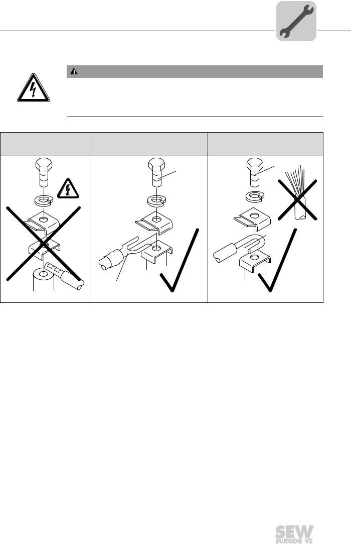
5.1.6Notes on PE connection
WARNING
Electric shock due to incorrect connection of PE. Severe or fatal injuries.
• The permitted tightening torque for the screw is 2.0 – 2.4 Nm (18 – 21 lb.in).
• Observe the following notes regarding PE connection.
|
Prohibited assembly |
Recommendation: |
Assembly with solid connecting wire |
|
Assembly with forked cable lug |
Permitted for cross sections up to |
|
|
Permitted for all cross sections |
max. 2.5 mm2 |
|
|
M5 |
M5 |
|
 2.5 mm²
[1]
|
323042443 |
323034251 |
323038347 |
[1]Forked cable lug suitable for M5 PE screws
Earth-leakage currents ≥ 3.5 mA can occur during normal operation. To meet the requirements of EN 61800-5-1, observe the following notes:
•The protective earth (PE) connection must meet the requirements for plants with high earth-leakage currents.
•This usually means
–installing a PE connection cable with a minimum cross section of 10 mm2
–or installing a second PE connection cable in parallel with the original PE connection.
|
Operating Instructions – MOVIMOT® MM..D with DRS/DRE/DRP AC Motor |
33 |
||

|
5 |
Electrical Installation |
|
|
Installation instructions |
||
5.1.7EMC-compliant installation
INFORMATION
This drive system is not designed for operation on a public low voltage supply system that supplies residential areas.
This is a product with restricted availability in accordance with IEC 61800-3. It may cause EMC interference. In this case, it is recommended for the operator to take suitable measures.
For detailed information on EMC compliant installation, refer to the publication «Electromagnetic Compatibility in Drive Engineering» from SEW-EURODRIVE.
With respect to the EMC regulation, frequency inverters cannot be operated as standalone units. Regarding EMC, they can only be evaluated when they are integrated in a drive system. Conformity is declared for a described, CE-typical drive system. These operating instructions contain further information.
5.1.8Installation above 1000 m asl
MOVIMOT® drives with line voltages of 200 – 240 V or 380 – 500 V, can be also used in altitudes of 1000 – 4000 m above sea level1). Observe the following conditions:
•The nominal continuous power is reduced due to the reduced cooling above 1000 m (see chapter «Technical Data»).
•Above 2000 m asl, the air and creeping distances are only sufficient for overvoltage class 2. If the installation calls for overvoltage class 3, you will have to install additional external overvoltage protection to limit overvoltage peaks to 2.5 kV phase-to- phase and phase-to-ground.
•If safe electrical disconnection is required, it must be implemented outside the unit for altitudes of 2000 m above sea level and higher (safe electrical disconnection in accordance with EN 61800-5-1).
•In installation altitudes between 2000 m to 4000 msl, the permitted nominal power supply voltages are reduced as follows:
–By 6 V per 100 m for MM..D-503-00
–By 3 V per 100 m for MM..D-233-00
5.1.9Connecting 24 V supply
•Power the MOVIMOT® inverter either via an external 24 V supply or the MLU..A or MLG..A options.
5.1.10Binary control
•Connect the required control leads.
•Use shielded cables as control cables and route them separately from supply system cables.
|
1) The maximum altitude is limited by creeping distances and flameproof components, such as capacitors. |
|
|
34 |
Operating Instructions – MOVIMOT® MM..D with DRS/DRE/DRP AC Motor |

Electrical Installation
Installation instructions
5.1.11 Control via RS-485 interface
The MOVIMOT® drive is controlled via the RS-485 interface by one of the following controllers:
•MOVIFIT® MC
•Fieldbus interfaces MF.. or MQ..
•PLC bus master
•MLG..A option
•MBG11A option
•MWA21A option
•MWF11A option
INFORMATION
•Connect only one bus master to the MOVIMOT® drive.
•Use shielded twisted-pair cables as control cables.
•Route the control cables separately from the power supply cables.
5.1.12Protection devices
•MOVIMOT® drives are equipped with integrated protection devices against overload. External overload devices are not necessary.
|
5.1.13 |
|
|
Field wiring power |
Note the following points for UL-compliant installation: |
|
terminals |
• Only use copper conductors with a thermal rating of 60/75 °C. |
|
• The permitted tightening torque of the power terminals is 1.5 Nm (13 Ib.in). |
|
|
Short circuit cur- |
Suitable for use on a circuit capable of delivering not more than 200,000 rms |
|
rent rating |
symmetrical amperes. |
|
The max. voltage is limited to 500 V. |
|
|
Branch circuit pro- |
Integral solid state short circuit protection does not provide branch circuit protection. |
|
tection |
Branch circuit protection must be provided in accordance with the National Electrical |
|
Code and any applicable local codes. |
|
|
The max. fuse rating is 25 A / 600 V. |
|
|
Motor overload |
MOVIMOT® MM..D is equipped with motor overload protection with a trip current ad- |
|
protection |
justed to 140% of the rated motor current. |
|
Ambient tempera- |
MOVIMOT® MM..D is suitable for an ambient temperature of 40 °C, max. 60 °C with de- |
|
ture |
rated output current. To determine the output current rating at higher than 40 °C, the out- |
|
put current should be derated 3.0 % per °C between 40 °C and 60 °C. |
Operating Instructions – MOVIMOT® MM..D with DRS/DRE/DRP AC Motor
|
5 |
Electrical Installation |
Connection of the MOVIMOT® drive |
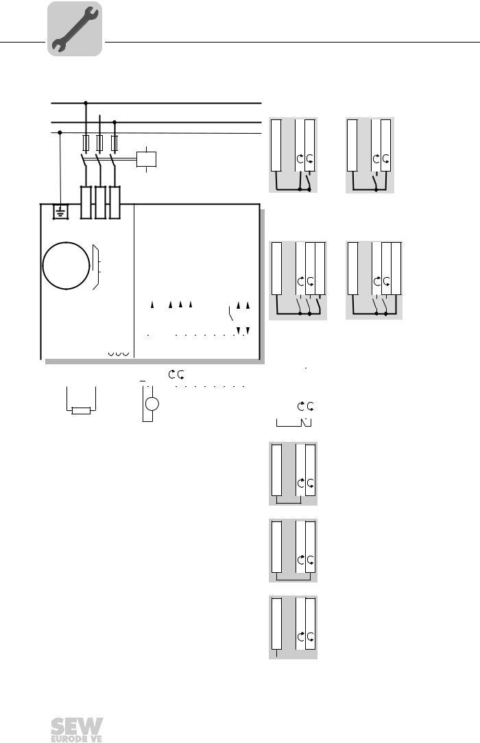
5.2Connection of the MOVIMOT® drive
L1
L2 
L3
PE
F11/F12/F13
K11
Functions of the CW/stop and CCW/stop terminals in binary control mode:
| <![if ! IE]>
<![endif]>X6:1,2,3 |
<![if ! IE]>
<![endif]>X6:11,12 X6:9,10 |
<![if ! IE]>
<![endif]>X6:1,2,3 |
<![if ! IE]>
<![endif]>X6:11,12 X6:9,10 |
| <![if ! IE]>
<![endif]>24V |
<![if ! IE]>
<![endif]>R L |
<![if ! IE]>
<![endif]>24V |
<![if ! IE]>
<![endif]>R L |
| <![if ! IE]>
<![endif]>X1:L1 |
<![if ! IE]>
<![endif]>X1:L2 |
<![if ! IE]>
<![endif]>X1:L3 |
|
MOVIMOT® |
|
M |
BE/BR |
||||||||||||||||||||||||||||||||||||||||
|
3~ |
|||||||||||||||||||||||||||||||||||||||||
|
485 |
|||||||||||||||||||||||||||||||||||||||||
|
— |
|||||||||||||||||||||||||||||||||||||||||
|
[1] |
[2] [3] [4] |
[5] |
[6] |
RS |
|||||||||||||||||||||||||||||||||||||
| <![if ! IE]>
<![endif]>WH |
<![if ! IE]>
<![endif]>K1 |
||||||||||||||||||||||||||||||||||||||||
| <![if ! IE]>
<![endif]>RD |
<![if ! IE]>
<![endif]>BU |
||||||||||||||||||||||||||||||||||||||||
| <![if ! IE]>
<![endif]>4,5,6 |
<![if ! IE]>
<![endif]>1,2,3 |
<![if ! IE]>
<![endif]>11,12 |
<![if ! IE]>
<![endif]>9,10 |
<![if ! IE]>
<![endif]>7,8 |
<![if ! IE]>
<![endif]>21,22 |
<![if ! IE]>
<![endif]>23,24 |
<![if ! IE]>
<![endif]>25,26 |
<![if ! IE]>
<![endif]>27,28 |
<![if ! IE]>
<![endif]>29,30 |
<![if ! IE]>
<![endif]>31,32 |
|||||||||||||||||||||||||||||||
|
13 |
14 |
15 |
|||||||||||||||||||||||||||||||||||||||
|
X1: |
X1: |
X1: |
<![if ! IE]>
<![endif]>X6: |
<![if ! IE]>
<![endif]>24V X6: |
<![if ! IE]>
<![endif]>R X6: |
<![if ! IE]>
<![endif]>L X6: |
<![if ! IE]>
<![endif]>f1/f2 X6: |
<![if ! IE]>
<![endif]>HT1 X5: |
<![if ! IE]>
<![endif]>HT2 X5: |
<![if ! IE]>
<![endif]>K1a X5: |
<![if ! IE]>
<![endif]>K1b X5: |
<![if ! IE]>
<![endif]>RSX5: |
<![if ! IE]>
<![endif]>RS+ X5: |
||||||||||||||||||||||||||||
| <![if ! IE]>
<![endif]>X10:1 X10:2 X10:3 |
|||||||||||||||||||||||||||||||||||||||||
[8]+
=DC 24 V
—
[7]
18014399135542795
|
Direction of rotation |
Direction of rotation |
||||
|
CW active |
CCW active |
||||
|
Functions of terminals f1/f2: |
|||||
| <![if ! IE]>
<![endif]>X6:1,2,3 |
<![if ! IE]>
<![endif]>X6:11,12 X6:9,10 |
<![if ! IE]>
<![endif]>X6: 7,8 |
<![if ! IE]>
<![endif]>X6:1,2,3 |
<![if ! IE]>
<![endif]>X6:11,12 X6:9,10 |
<![if ! IE]>
<![endif]>X6: 7,8 |
| <![if ! IE]>
<![endif]>24V |
<![if ! IE]>
<![endif]>R L |
<![if ! IE]>
<![endif]>f1/f2 |
<![if ! IE]>
<![endif]>24V |
<![if ! IE]>
<![endif]>R L |
<![if ! IE]>
<![endif]>f1/f2 |
|
Setpoint f1 active |
Setpoint f2 active |
Functions of the CW/stop and CCW/stop terminals with control via RS-485 interface/fieldbus:
| <![if ! IE]>
<![endif]>11,12 |
|||||
| <![if ! IE]>
<![endif]>1,2,3 |
<![if ! IE]>
<![endif]>9,10 |
Both directions of rotation |
|||
| <![if ! IE]>
<![endif]>X6: |
<![if ! IE]>
<![endif]>X6: |
<![if ! IE]>
<![endif]>X6: |
|||
|
are enabled |
|||||
| <![if ! IE]>
<![endif]>24V |
|||||
| <![if ! IE]>
<![endif]>R |
<![if ! IE]>
<![endif]>L |
||||
<![if ! IE]>
<![endif]>24V X6: 1,2,3
<![if ! IE]>
<![endif]>R X6: 11,12 L X6: 9,10
Only CW direction is enabled
Pre-selected setpoints for CCW rotation result in standstill of drive
[1] DC 24 V supply
(external or via option MLU..A / MLG..A)
[2]CW/stop
[3]CCW/stop
[4]Setpoint changeover f1/f2
[5]HT1 / HT2: Intermediate terminal for specific wiring diagrams
[6]Ready signal
(contact closed = ready for operation) [7] BW.. braking resistor
(only for MOVIMOT® drives without mechanical brake) [8] Plug connector for connecting the options BEM + BES
| <![if ! IE]>
<![endif]>X6:1,2,3 |
<![if ! IE]>
<![endif]>X6:11,12 |
<![if ! IE]>
<![endif]>X6:9,10 |
| <![if ! IE]>
<![endif]>24V |
<![if ! IE]>
<![endif]>R L |
|
| <![if ! IE]>
<![endif]>X6:1,2,3 |
<![if ! IE]>
<![endif]>X6:11,12 |
<![if ! IE]>
<![endif]>X6:9,10 |
| <![if ! IE]>
<![endif]>24V |
<![if ! IE]>
<![endif]>R L |
Only CCW operation is enabled
Setpoint specifications for CW operation
cause standstill of the drive
Drive is inhibited or is being brought to a standstill
|
36 |
Operating Instructions – MOVIMOT® MM..D with DRS/DRE/DRP AC Motor |
||
|
Electrical Installation |
5 |
MOVIMOT® plug connectors |
5.3MOVIMOT® plug connectors
5.3.1AVT1, ASA3 plug connectors
The following figure shows the assignment of optional AVT1 and ASA3 plug connectors.
Available versions:
•MM../ASA3
•MM../AVT1
•MM../ASA3/AVT1
MOVIMOT®
1 2 3 4 5
4
 3
3
1
 2
2
6 7 8 9 10
323830155
5.3.2AMA6 plug connectors
The following illustration shows the assignment of the optional AMA6 plug connector.
Possible design:
•MM../AMA6
|
MOVIMOT® |
|||
|
RS- |
L3 |
||
|
RS+ |
L1 |
||
|
24 V |
L2 |
||
|
C |
1 |
1 |
A |
|
3 |
2 |
3 |
2 |
|
5 |
4 |
5 |
4 |
|
6 |
6 |
||
|
AMA6 |
323879563
INFORMATION
For designs with plug connectors, both directions of rotation are enabled as standard.
If only one direction of rotation is required, please observe chapter «Connection of the
MOVIMOT® drive, functions of the terminals CW/stop, CCW/stop for connection via
RS-485 interface».
|
Operating Instructions – MOVIMOT® MM..D with DRS/DRE/DRP AC Motor |
37 |
||
|
5 |
Electrical Installation |
|
Connection between MOVIMOT® and motor when mounted close to the |
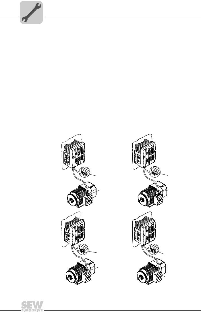
5.4Connection between MOVIMOT® and motor when mounted close to the motor
If the MOVIMOT® inverter is mounted close to the motor, the connection to the motor is realized with a pre-fabricated hybrid cable.
Use only hybrid cables from SEW-EURODRIVE to connect the MOVIMOT® inverter with the motor.
The following designs are possible on the MOVIMOT® side:
•A: MM../P2.A/RO.A/APG4
•B: MM../P2.A/RE.A/ALA4
The APG4 type results in the following connection options to the motor, depending on the hybrid cable used:
|
Design |
A1 |
A2 |
A3 |
A4 |
|
|
MOVIMOT® |
APG4 |
APG4 |
APG4 |
APG4 |
|
|
Motor |
Cable gland/ |
ASB4 |
APG4 |
ISU4 |
|
|
terminals |
|||||
|
Hybrid cable |
0 186 742 3 |
0 593 076 6 |
0 186 741 5 |
0 816 325 1 |
for DR.63 |
|
0 816 326 X for DR.71–DR.132 |
|||||
|
0 593 278 5 |
for DR.63 |
||||
|
0 593 755 8 |
for DR.71–DR.132 |
|
A3 |
A4 |
||
|
APG4 |
APG4 |
||
|
APG4 |
|||
|
ISU4 |
|||
|
[1] Connection via terminals |
458666635 |
||
|
38 |
Operating Instructions – MOVIMOT® MM..D with DRS/DRE/DRP AC Motor |
|
Electrical Installation |
5 |
|
Connection between MOVIMOT® and motor when mounted close to the |
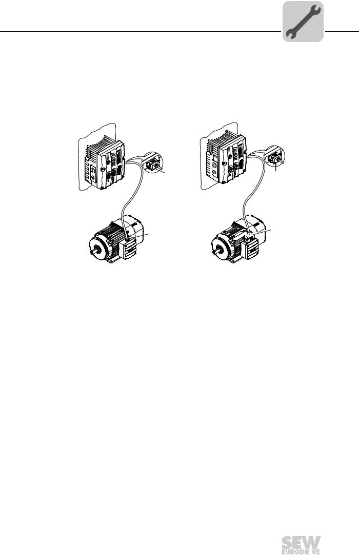
The APG4 design results in the following connection options to the motor, dependent upon the hybrid cable used:
|
Design |
B1 |
B2 |
|
MOVIMOT® |
ALA4 |
ALA4 |
|
Motor |
Cable gland/terminals |
ASB4 |
|
Hybrid cable |
0 817 948 4 |
0 816 208 5 |


 ASB4 [1]


458688139
[1] Connection via terminals
|
Operating Instructions – MOVIMOT® MM..D with DRS/DRE/DRP AC Motor |
39 |
||

|
5 |
Electrical Installation |
|
Connection between MOVIMOT® and motor when mounted close to the |
5.4.1Overview of connections between MOVIMOT® and motor when mounted close to the motor
|
MOVIMOT® inverter |
Design |
Hybrid cable |
Drive |
||||||||||||||||||||||||||||||||||||||||||||
|
MM../P2.A/RO.A/APG4 |
A1 |
Part number DR71 – DR100: 0 186 742 3 |
AC motors with cable gland |
||||||||||||||||||||||||||||||||||||||||||||
|
Part number DR112 – DR132: 1 811 662 0 |
|||||||||||||||||||||||||||||||||||||||||||||||
|
A2 |
Part number: 0 593 076 6 |
AC motors with ASB4 plug |
|||||||||||||||||||||||||||||||||||||||||||||||||||||||||||||||||
|
APG4 |
connector |
||||||||||||||||||||||||||||||||||||||||||||||||||||||||||||||||||
|
A3 |
Part number: 0 186 741 5 |
AC motors with APG4 plug |
||||||||||||||||||||||||||||||||||||||||
|
connector |
||||||||||||||||||||||||||||||||||||||||||
|
A4 |
Part number: 0 593 278 5 |
( ) |
AC motors with plug connec- |
|
Part number: 0 816 325 1 |
( ) |
tor ISU4 |
|
|
Size DR.63 |
<![if ! IE]>
<![endif]>593 278 5
|
A4 |
Part number: 0 593 755 |
8 ( ) |
AC motors with plug connec- |
|
Part number: 0 816 326 |
X ( ) |
tor ISU4 |
|
|
Size DR.71-DR.132 |
<![if ! IE]>
<![endif]>593 278 5
|
MM../P2.A/RE.A/ALA4 |
B1 |
Part number: 0 817 948 4 |
AC motors with cable gland |
|||||||||||||||||||||||||||||||||||||||||
|
B2 |
Part number: 0 816 208 5 |
AC motors with ASB4 plug |
|
connector |
ALA4
|
40 |
Operating Instructions – MOVIMOT® MM..D with DRS/DRE/DRP AC Motor |
||
![]()
|
Electrical Installation |
5 |
|
Connection between MOVIMOT® and motor when mounted close to the |
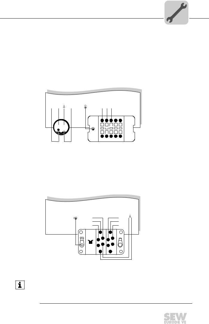
5.4.2Hybrid cable connection
The following tables shows the conductor assignment in hybrid cables with part no. 0 186 742 3 and 0 817 948 4 and the corresponding motor terminals of the DR motor:
|
DR motor terminal |
Wire color/hybrid cable designation |
|
U1 |
Black/U1 |
|
V1 |
Black/V1 |
|
W1 |
Black/W1 |
|
4a |
Red/13 |
|
3a |
White/14 |
|
5a |
Blue/15 |
|
1b |
Black/1 |
|
2b |
Black/2 |
|
PE connection |
Green/yellow + shield end (internal shield) |
The following figure shows the connection of the hybrid cable to the terminal box of the
DR motor.
|
PE |
|||||||
|
U1 |
V1 |
W1 |
BK/W1 |
||||
|
BK/V1 |
|||||||
|
BK/U1 |
|||||||
|
1 a 2 a 3 a 4 a 5 a |
BU |
||||||
|
RD |
|||||||
|
WH |
|||||||
|
1b |
BK/1 |
||||||
|
2b |
BK/2 |
||||||
|
W2 |
U2 |
V2 |
W2 |
U2 |
V2 |
||
|
U1 |
V1 |
W1 |
U1 |
V1 |
W1 |
9007200445548683
|
Operating Instructions – MOVIMOT® MM..D with DRS/DRE/DRP AC Motor |
41 |
||
|
5 |
Electrical Installation |
Connection of the MOVIMOT® options |
5.5Connection of the MOVIMOT® options
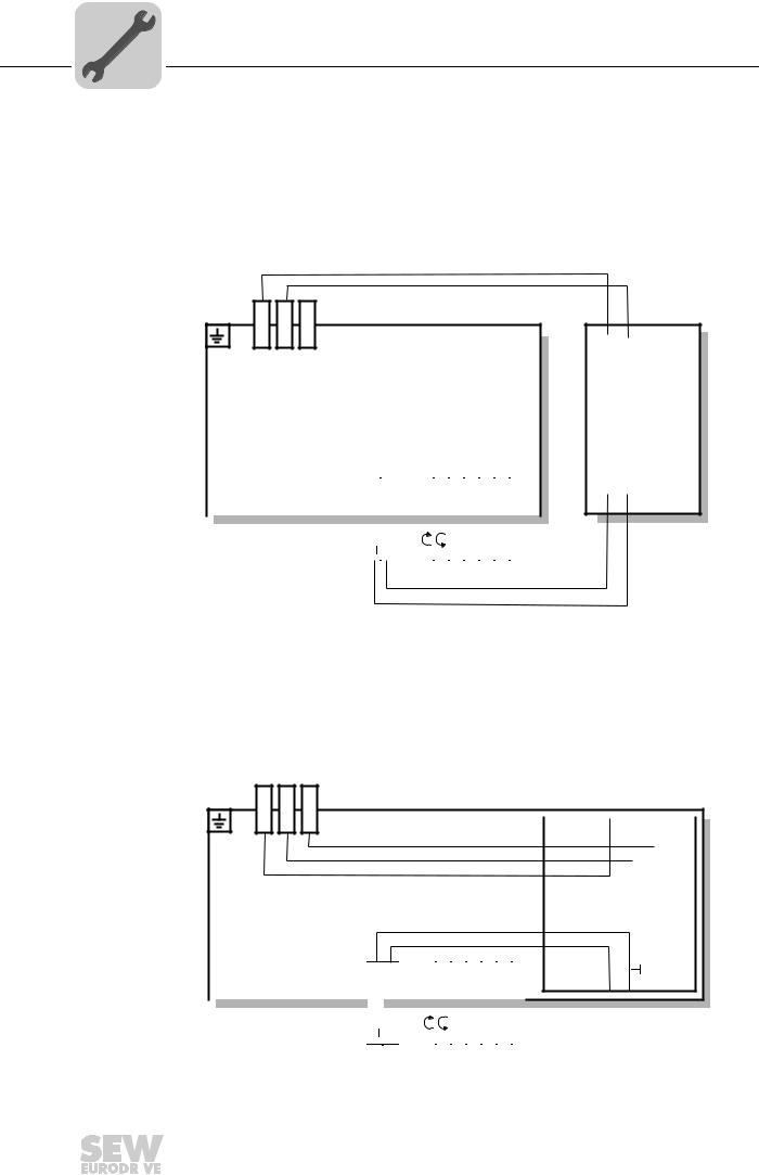
5.5.1Connecting the MLU11A/MLU21A option
For more information about connecting the MLU11A and MLU21A options, refer to sec. «Connection of option MLU11A/MLU21A/MLG..A» (page 20).
The following figure shows how to connect the MLU11A and MLU21A options:
|
YE (MLU11A), BN (MLU21A) |
||
|
YE (MLU11A), BN (MLU21A) |
||
| <![if ! IE]>
<![endif]>X1:L1 |
<![if ! IE]>
<![endif]>X1:L2 |
<![if ! IE]>
<![endif]>X1:L3 |
|
MOVIMOT® |
| <![if ! IE]>
<![endif]>4,5,6 |
<![if ! IE]>
<![endif]>1,2,3 |
<![if ! IE]>
<![endif]>11,12 |
<![if ! IE]>
<![endif]>9,10 |
<![if ! IE]>
<![endif]>7,8 |
<![if ! IE]>
<![endif]>25,26 |
<![if ! IE]>
<![endif]>27,28 |
<![if ! IE]>
<![endif]>29,30 |
<![if ! IE]>
<![endif]>31,32 |
|||||||||
|
13 |
14 |
15 |
|||||||||||||||
|
X1: |
X1: |
X1: |
<![if ! IE]>
<![endif]>X6: |
<![if ! IE]>
<![endif]>X6: |
<![if ! IE]>
<![endif]>X6: |
<![if ! IE]>
<![endif]>X6: |
<![if ! IE]>
<![endif]>X6: |
<![if ! IE]>
<![endif]>X5: |
<![if ! IE]>
<![endif]>X5: |
<![if ! IE]>
<![endif]>X5: |
<![if ! IE]>
<![endif]>X5: |
||||||
| <![if ! IE]>
<![endif]>24V |
<![if ! IE]>
<![endif]>R |
<![if ! IE]>
<![endif]>L |
<![if ! IE]>
<![endif]>f1/f2 |
<![if ! IE]>
<![endif]>K1a |
<![if ! IE]>
<![endif]>K1b |
<![if ! IE]>
<![endif]>RS- |
<![if ! IE]>
<![endif]>RS+ |
||||||||||
RD
BU
| <![if ! IE]>
<![endif]>L1 |
<![if ! IE]>
<![endif]>L2 |
MLU..A
<![if ! IE]>
<![endif]>24V
640436235
5.5.2Connection of MLU13A option
For more information about mounting the MLU13A option, refer to chapter «MLU13A option» (page 20).
The following figure shows how to connect the MLU13A option:
| <![if ! IE]>
<![endif]>X1: L1 |
<![if ! IE]>
<![endif]>X1: L2 |
<![if ! IE]>
<![endif]>X1: L3 |
|
13 |
14 |
15 |
||||
|
X1: |
X1: |
X1: |
||||
MOVIMOT®
YE
YE
YE
|
BU |
|||||||||
|
RD |
|||||||||
| <![if ! IE]>
<![endif]>X6: 4,5,6 |
<![if ! IE]>
<![endif]>X6: 1,2,3 |
<![if ! IE]>
<![endif]>X6: 11,12 |
<![if ! IE]>
<![endif]>X6: 9,10 |
<![if ! IE]>
<![endif]>X6: 7,8 |
<![if ! IE]>
<![endif]>X5: 25,26 |
<![if ! IE]>
<![endif]>X5: 27,28 |
<![if ! IE]>
<![endif]>X5: 29,30 |
<![if ! IE]>
<![endif]>X5: 31,32 |
|
| <![if ! IE]>
<![endif]>24V |
<![if ! IE]>
<![endif]>R |
<![if ! IE]>
<![endif]>L |
<![if ! IE]>
<![endif]>f1/f2 |
<![if ! IE]>
<![endif]>K1a |
<![if ! IE]>
<![endif]>K1b |
<![if ! IE]>
<![endif]>RS- |
<![if ! IE]>
<![endif]>RS+ |
||
| <![if ! IE]>
<![endif]>L1 |
<![if ! IE]>
<![endif]>L2 |
<![if ! IE]>
<![endif]>L3 |
|
MLU13A
<![if ! IE]>
<![endif]>24V
323967371
|
42 |
Operating Instructions – MOVIMOT® MM..D with DRS/DRE/DRP AC Motor |
||
|
Electrical Installation |
5 |
|
Connection of the MOVIMOT® options |
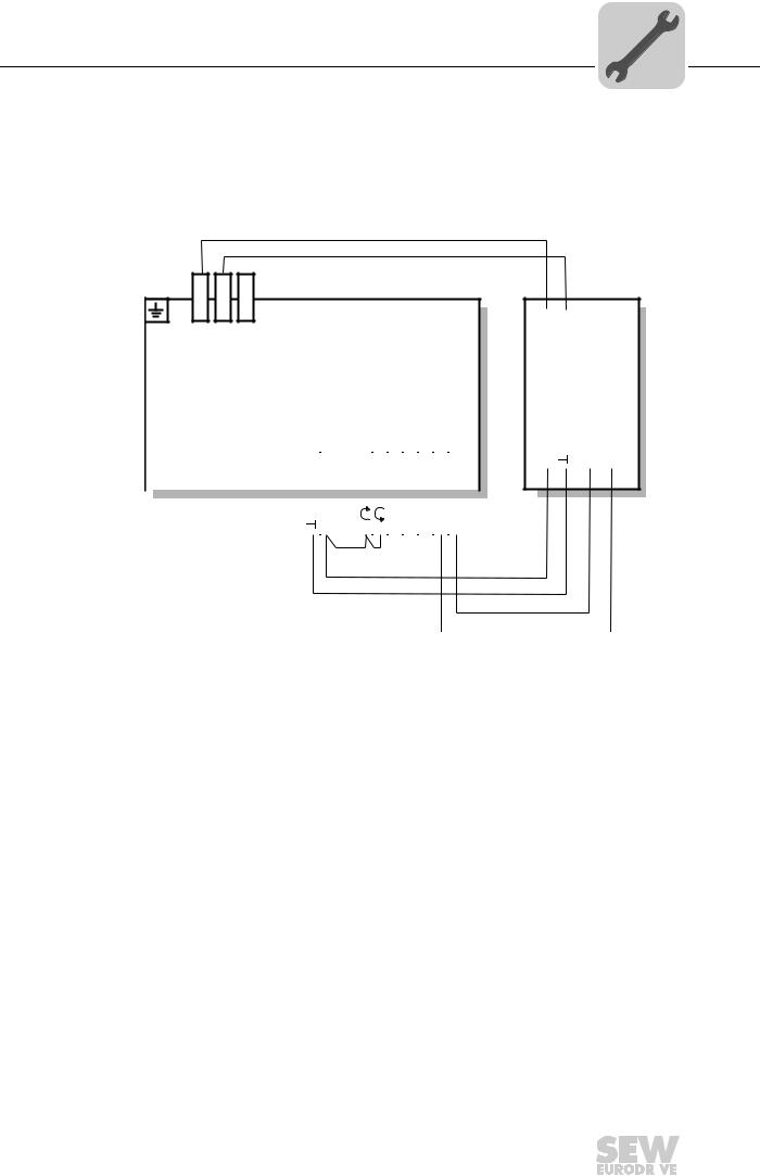
5.5.3Connection of option MLG..A
For more information about mounting the MLG..A option, refer to sec. «MLU11A/
MLU21A/MLG..A option» (page 20).
The following figure shows how to connect the MLG..A option:
|
YE (MLG11A), BN (MLG21A) |
|||
|
YE (MLG11A), BN (MLG21A) |
|||
| <![if ! IE]>
<![endif]>X1: L1 |
<![if ! IE]>
<![endif]>X1: L2 |
<![if ! IE]>
<![endif]>X1: L3 |
MOVIMOT® |
| <![if ! IE]>
<![endif]>4,5,6 |
<![if ! IE]>
<![endif]>1,2,3 |
<![if ! IE]>
<![endif]>11,12 |
<![if ! IE]>
<![endif]>9,10 |
<![if ! IE]>
<![endif]>7,8 |
<![if ! IE]>
<![endif]>25,26 |
<![if ! IE]>
<![endif]>27,28 |
<![if ! IE]>
<![endif]>29,30 |
<![if ! IE]>
<![endif]>31,32 |
|||||||||
|
13 |
14 |
15 |
|||||||||||||||
|
X1: |
X1: |
X1: |
<![if ! IE]>
<![endif]>X6: |
<![if ! IE]>
<![endif]>X6: |
<![if ! IE]>
<![endif]>X6: |
<![if ! IE]>
<![endif]>X6: |
<![if ! IE]>
<![endif]>X6: |
<![if ! IE]>
<![endif]>X5: |
<![if ! IE]>
<![endif]>X5: |
<![if ! IE]>
<![endif]>X5: |
<![if ! IE]>
<![endif]>X5: |
||||||
| <![if ! IE]>
<![endif]>24V |
<![if ! IE]>
<![endif]>R |
<![if ! IE]>
<![endif]>L |
<![if ! IE]>
<![endif]>f1/f2 |
<![if ! IE]>
<![endif]>K1a |
<![if ! IE]>
<![endif]>K1b |
<![if ! IE]>
<![endif]>RS- |
<![if ! IE]>
<![endif]>RS+ |
||||||||||
[1]
| <![if ! IE]>
<![endif]>L1 |
<![if ! IE]>
<![endif]>L2 |
MLG..A
| <![if ! IE]>
<![endif]>24V |
<![if ! IE]>
<![endif]>RS+ |
<![if ! IE]>
<![endif]>RS- |
<![if ! IE]>
<![endif]>RD BU OG GN
641925899
[1]Note the enabled direction of rotation.
See chapter «Connection of the MOVIMOT® drive» (page 36),
Functions of the CW/Stop and CCW/Stop terminals using control via RS-485 interface
|
Operating Instructions – MOVIMOT® MM..D with DRS/DRE/DRP AC Motor |
43 |
||
|
5 |
Electrical Installation |
|
Connection of the MOVIMOT® options |
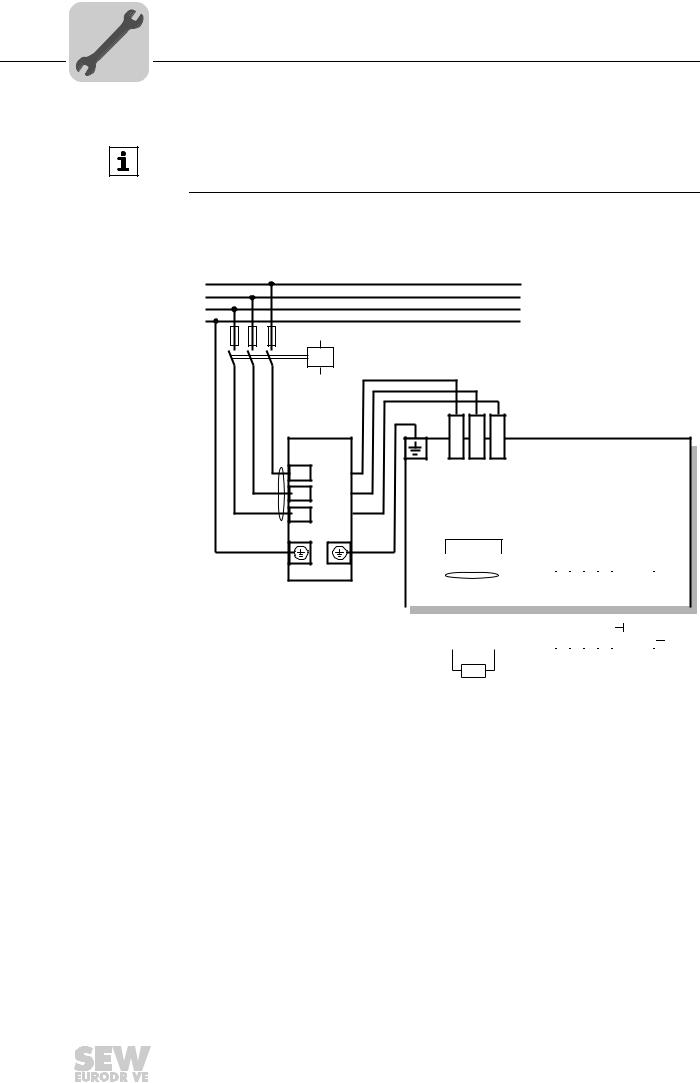
5.5.4Connection of MNF21A option
INFORMATION
Only install this option in combination with the modular connection box of MOVIMOT®
MM03D-503-00 – MM15D-503-00.
For more information about mounting the MNF21A option, refer to chapter «MNF21A option» (page 22).
The following figure shows how to connect the MNF21A option:
L1
L2
L3
PE
F11/F12/F13
K11
|
MNF21A |
|
|
[1] |
|
|
L1 |
L1 |
|
L2 |
L2 |
|
L3 |
L3 |
| <![if ! IE]>
<![endif]>L1 |
<![if ! IE]>
<![endif]>L2 |
<![if ! IE]>
<![endif]>L3 |
||
| <![if ! IE]>
<![endif]>X1: |
<![if ! IE]>
<![endif]>X1: |
<![if ! IE]>
<![endif]>X1: |
MOVIMOT |
® |
BE/BR
|
RD |
WH |
BU |
||||||||||||||||||
|
[2] |
||||||||||||||||||||
| <![if ! IE]>
<![endif]>3,4 |
<![if ! IE]>
<![endif]>1,2 |
<![if ! IE]>
<![endif]>2a,2b |
<![if ! IE]>
<![endif]>1a,1b |
|||||||||||||||||
|
13 |
14 |
15 |
<![if ! IE]>
<![endif]>8 |
<![if ! IE]>
<![endif]>7 |
<![if ! IE]>
<![endif]>6 |
<![if ! IE]>
<![endif]>5 |
||||||||||||||
|
X1: |
X1: |
X1: |
<![if ! IE]>
<![endif]>X6: |
<![if ! IE]>
<![endif]>X6: |
<![if ! IE]>
<![endif]>X6: |
<![if ! IE]>
<![endif]>X6: |
<![if ! IE]>
<![endif]>X6: |
<![if ! IE]>
<![endif]>X6: |
<![if ! IE]>
<![endif]>X5: |
<![if ! IE]>
<![endif]>X5: |
||||||||||
| <![if ! IE]>
<![endif]>AS+ |
<![if ! IE]>
<![endif]>AS- |
<![if ! IE]>
<![endif]>DI2 |
<![if ! IE]>
<![endif]>DI3 |
<![if ! IE]>
<![endif]>V024 |
<![if ! IE]>
<![endif]>V0 |
<![if ! IE]>
<![endif]>24V |
||||||||||||||
 [2]
[2]
BW
[3]
1754451723
[1]Keep the cable length for the power supply as short as possible!
[2]Keep the length of the brake cables as short as possible!
Do not route the brake cables in parallel, but as far away from the power supply cables as possible!
[3]BW braking resistor (only in MOVIMOT® without mechanical brake)
|
44 |
Operating Instructions – MOVIMOT® MM..D with DRS/DRE/DRP AC Motor |
||
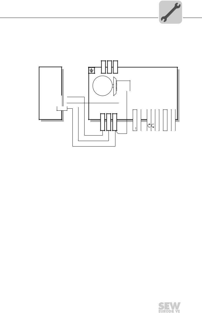
|
Electrical Installation |
5 |
|
Connection of the MOVIMOT® options |
5.5.5Connection of URM option
For more information about mounting the URM option, refer to chapter «URM/BEM option» (page 23).
The following figure shows how to connect the URM option:
|
URM |
<![if ! IE]>
<![endif]>X1: L1 |
<![if ! IE]>
<![endif]>X1: L2 |
<![if ! IE]>
<![endif]>X1: L3 |
MOVIMOT® |
|
13 |
||||||
|
RD |
||||||
|
14 |
||||||
|
WH |
||||||
|
15 |
||||||
|
13 |
14 |
15 |
<![if ! IE]>
<![endif]>4,5,6 |
<![if ! IE]>
<![endif]>1,2,3 |
<![if ! IE]>
<![endif]>11,12 |
<![if ! IE]>
<![endif]>9,10 |
<![if ! IE]>
<![endif]>7,8 |
<![if ! IE]>
<![endif]>25,26 |
<![if ! IE]>
<![endif]>27,28 |
<![if ! IE]>
<![endif]>29,30 |
<![if ! IE]>
<![endif]>31,32 |
|
X1: |
X1: |
X1: |
<![if ! IE]>
<![endif]>X6: |
<![if ! IE]>
<![endif]>X6: |
<![if ! IE]>
<![endif]>X6: |
<![if ! IE]>
<![endif]>X6: |
<![if ! IE]>
<![endif]>X6: |
<![if ! IE]>
<![endif]>X5: |
<![if ! IE]>
<![endif]>X5: |
<![if ! IE]>
<![endif]>X5: |
<![if ! IE]>
<![endif]>X5: |
| <![if ! IE]>
<![endif]>24V |
<![if ! IE]>
<![endif]>R |
<![if ! IE]>
<![endif]>L |
<![if ! IE]>
<![endif]>f1/f2 |
<![if ! IE]>
<![endif]>K1a |
<![if ! IE]>
<![endif]>K1b |
<![if ! IE]>
<![endif]>RS- |
<![if ! IE]>
<![endif]>RS+ |
BU
324118411
|
Operating Instructions – MOVIMOT® MM..D with DRS/DRE/DRP AC Motor |
45 |
||
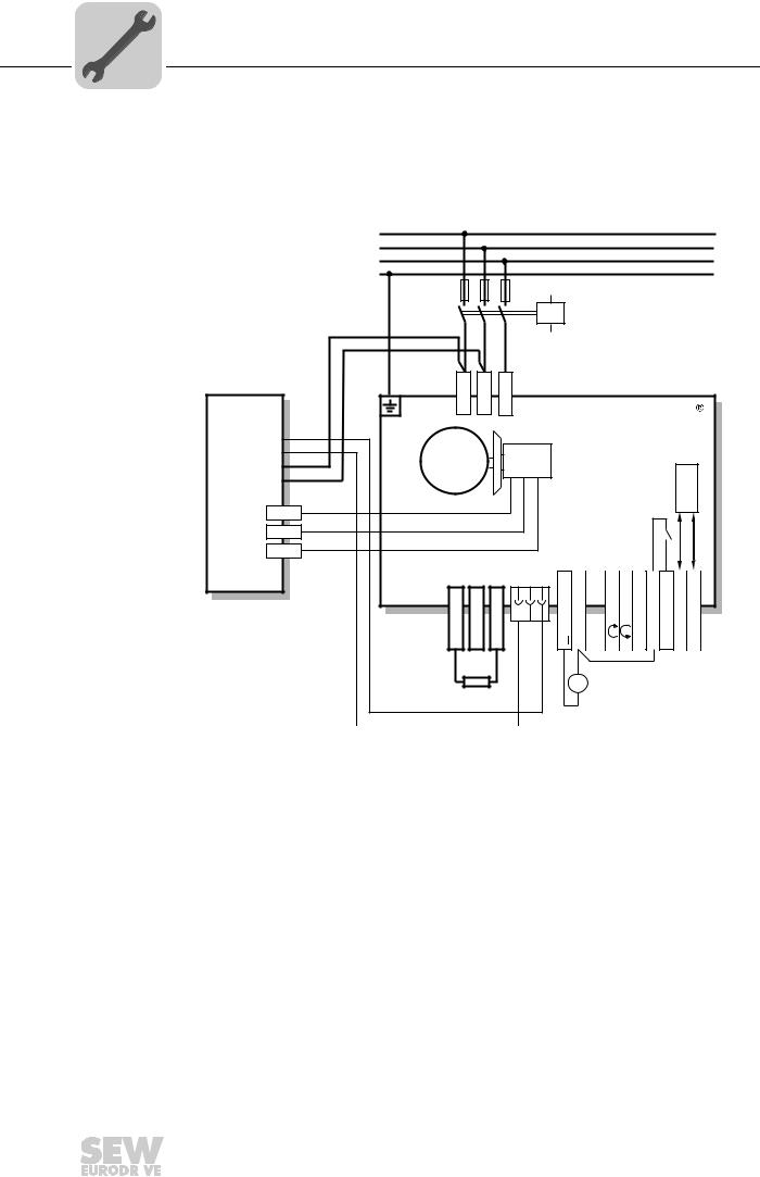
|
5 |
Electrical Installation |
|
Connection of the MOVIMOT® options |
5.5.6Connection of BEM option
For more information about mounting the BEM option, refer to chapter «URM/BEM/BES option» (page 23).
The following figure shows how to connect the BEM option:
|
L1 |
||||||||||||||||||
|
L2 |
||||||||||||||||||
|
L3 |
||||||||||||||||||
|
PE |
||||||||||||||||||
|
F11/F12/F13 |
||||||||||||||||||
|
K11 |
||||||||||||||||||
|
BEM |
<![if ! IE]>
<![endif]>X1: L1 |
<![if ! IE]>
<![endif]>X1: L2 |
<![if ! IE]>
<![endif]>X1: L3 |
MOVIMOT |
||||||||||||||
|
U |
<![if ! IE]>
<![endif]>+ |
RD |
||||||||||||||||
|
IN |
BU |
|||||||||||||||||
| <![if ! IE]>
<![endif]>_ |
M |
|||||||||||||||||
|
BK |
BE/BR |
|||||||||||||||||
|
U |
<![if ! IE]>
<![endif]>~ |
3~ |
485 |
|||||||||||||||
|
E |
<![if ! IE]>
<![endif]>~ |
BK |
||||||||||||||||
|
— |
||||||||||||||||||
|
RD |
RS |
|||||||||||||||||
|
13 |
||||||||||||||||||
|
14 |
WH |
<![if ! IE]>
<![endif]>K1 |
||||||||||||||||
|
15 |
BU |
|||||||||||||||||
| <![if ! IE]>
<![endif]>X10:1 |
<![if ! IE]>
<![endif]>X10:2 |
<![if ! IE]>
<![endif]>X10:3 |
||||||||||||||||
|
13 |
14 |
15 |
<![if ! IE]>
<![endif]>4,5,6 |
<![if ! IE]>
<![endif]>1,2,3 |
<![if ! IE]>
<![endif]>11,12 |
<![if ! IE]>
<![endif]>9,10 |
<![if ! IE]>
<![endif]>7,8 |
<![if ! IE]>
<![endif]>25,26 |
<![if ! IE]>
<![endif]>27,28 |
<![if ! IE]>
<![endif]>29,30 |
<![if ! IE]>
<![endif]>31,32 |
|||||||
|
X1: |
X1: |
X1: |
<![if ! IE]>
<![endif]>X6: |
<![if ! IE]>
<![endif]>X6: |
<![if ! IE]>
<![endif]>X6: |
<![if ! IE]>
<![endif]>X6: X6: X5: X5: X5: X5: |
||||||||||||
| <![if ! IE]>
<![endif]>24V |
<![if ! IE]>
<![endif]>R |
<![if ! IE]>
<![endif]>L |
<![if ! IE]>
<![endif]>f1/f2 |
<![if ! IE]>
<![endif]>K1a |
<![if ! IE]>
<![endif]>K1b |
<![if ! IE]>
<![endif]>RS- |
<![if ! IE]>
<![endif]>RS+ |
|||||||||||
|
+ |
||||||||||||||||||
|
= |
||||||||||||||||||
|
BW.. |
— |
|||||||||||||||||
|
324134539 |
|
46 |
Operating Instructions – MOVIMOT® MM..D with DRS/DRE/DRP AC Motor |
||
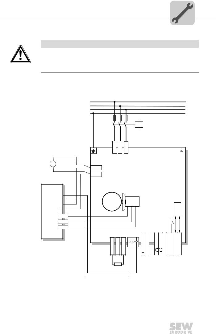
|
Electrical Installation |
5 |
|
Connection of the MOVIMOT® options |
5.5.7Connection of BES option
NOTICE
If the connection voltage is too high, the BES option or the brake coil connected to it can be damaged.
Damage to the BES option or the brake coil.
•Select a brake with a DC 24 V brake coil.
For more information about mounting the BES option, refer to chapter «URM/BEM/BES option» (page 23).
The following figure shows how to connect the BES option:
|
+ |
|
|
24 V |
= |
|
— |
|
|
BES [1] |
|
| <![if ! IE]>
<![endif]>IN |
|
| <![if ! IE]>
<![endif]>U |
|
| <![if ! IE]>
<![endif]>E |
|
| <![if ! IE]>
<![endif]>U |
|
L1 |
|||||||||||||||||
|
L2 |
|||||||||||||||||
|
L3 |
|||||||||||||||||
|
PE |
|||||||||||||||||
|
F11/F12/F13 |
|||||||||||||||||
|
K11 |
|||||||||||||||||
| <![if ! IE]>
<![endif]>X1: L1 |
<![if ! IE]>
<![endif]>X1: L2 |
<![if ! IE]>
<![endif]>X1: L3 |
MOVIMOT |
||||||||||||||
|
[3] |
|||||||||||||||||
|
DR.. |
|||||||||||||||||
|
+ |
RD |
||||||||||||||||
| <![if ! IE]>
<![endif]>- |
BU |
M |
|||||||||||||||
| <![if ! IE]>
<![endif]>24V |
RD |
3~ |
BE… |
485 |
|||||||||||||
|
BK |
|||||||||||||||||
|
— |
|||||||||||||||||
|
RD |
RS |
||||||||||||||||
|
13 |
|||||||||||||||||
|
14 |
WH |
<![if ! IE]>
<![endif]>K1 |
|||||||||||||||
|
15 |
BU |
||||||||||||||||
| <![if ! IE]>
<![endif]>X10:1 |
<![if ! IE]>
<![endif]>X10:2 |
<![if ! IE]>
<![endif]>X10:3 |
|||||||||||||||
|
13 |
14 |
15 |
<![if ! IE]>
<![endif]>4,5,6 |
<![if ! IE]>
<![endif]>1,2,3 |
<![if ! IE]>
<![endif]>11,12 |
<![if ! IE]>
<![endif]>9,10 |
<![if ! IE]>
<![endif]>7,8 |
<![if ! IE]>
<![endif]>25,26 |
<![if ! IE]>
<![endif]>27,28 |
<![if ! IE]>
<![endif]>29,30 |
<![if ! IE]>
<![endif]>31,32 |
||||||
|
X1: |
X1: |
X1: |
<![if ! IE]>
<![endif]>X6: |
<![if ! IE]>
<![endif]>X6: |
<![if ! IE]>
<![endif]>X6: |
<![if ! IE]>
<![endif]>X6: |
<![if ! IE]>
<![endif]>X6: |
<![if ! IE]>
<![endif]>X5: |
<![if ! IE]>
<![endif]>X5: |
<![if ! IE]>
<![endif]>X5: |
<![if ! IE]>
<![endif]>X5: |
||||||
| <![if ! IE]>
<![endif]>24V |
<![if ! IE]>
<![endif]>R |
<![if ! IE]>
<![endif]>L |
<![if ! IE]>
<![endif]>f1/f2 |
<![if ! IE]>
<![endif]>K1a |
<![if ! IE]>
<![endif]>K1b |
<![if ! IE]>
<![endif]>RS- |
<![if ! IE]>
<![endif]>RS+ |
||||||||||
|
[2] |
|||||||||||||||||
|
1711602315 |
[1]BES brake control mounted in the connection box
[2]External BW braking resistor
[3]Additional terminals for DC 24 V brake supply
|
Operating Instructions – MOVIMOT® MM..D with DRS/DRE/DRP AC Motor |
47 |
||
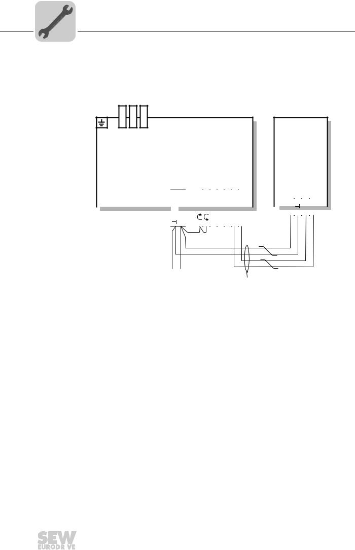
|
5 |
Electrical Installation |
|
Connection of the MOVIMOT® options |
5.5.8Connection of MBG11A option
For more information about mounting the MBG11A option, refer to sec. «MBG11A option» (page 24).
The following figure shows how to connect the MBG11A option:
| <![if ! IE]>
<![endif]>X1: L1 |
<![if ! IE]>
<![endif]>X1: L2 |
<![if ! IE]>
<![endif]>X1: L3 |
|
13 |
14 |
15 |
||||
|
X1: |
X1: |
X1: |
||||
MOVIMOT®
MBG11A
| <![if ! IE]>
<![endif]>X6: 4,5,6 |
<![if ! IE]>
<![endif]>X6: 1,2,3 |
<![if ! IE]>
<![endif]>X6: 11,12 |
<![if ! IE]>
<![endif]>X6: 9,10 |
<![if ! IE]>
<![endif]>X6: 7,8 |
<![if ! IE]>
<![endif]>X5: 25,26 |
<![if ! IE]>
<![endif]>X5: 27,28 |
<![if ! IE]>
<![endif]>X5: 29,30 |
<![if ! IE]>
<![endif]>X5: 31,32 |
|||||||||
| <![if ! IE]>
<![endif]>24V |
<![if ! IE]>
<![endif]>RS+ |
<![if ! IE]>
<![endif]>RS- |
|||||||||||||||
| <![if ! IE]>
<![endif]>24V |
<![if ! IE]>
<![endif]>R |
<![if ! IE]>
<![endif]>L |
<![if ! IE]>
<![endif]>f1/f2 |
<![if ! IE]>
<![endif]>K1a |
<![if ! IE]>
<![endif]>K1b |
<![if ! IE]>
<![endif]>RS- |
<![if ! IE]>
<![endif]>RS+ |
||||||||||
[1]
 24 VDC
[2]
324046731
[1]Note the enabled direction of rotation.
See chapter «Connection of the MOVIMOT® drive» (page 36),
Functions of the CW/Stop and CCW/Stop terminals using control via RS-485 interface
[2]EMC metal cable gland
|
48 |
Operating Instructions – MOVIMOT® MM..D with DRS/DRE/DRP AC Motor |
||
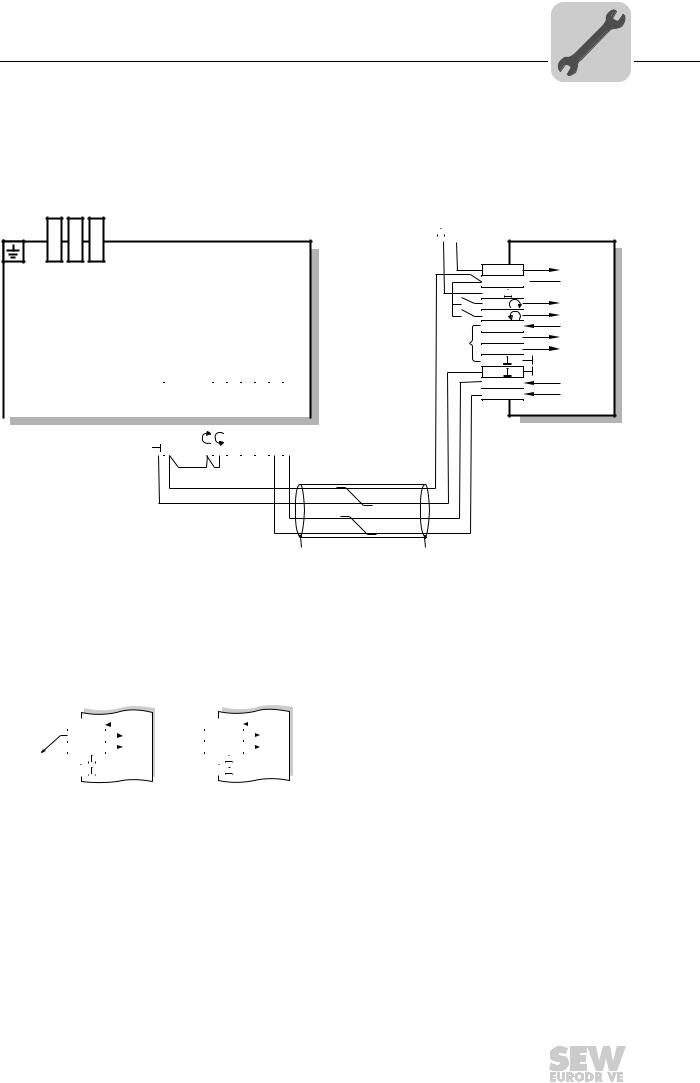
|
Electrical Installation |
5 |
|
Connection of the MOVIMOT® options |
5.5.9Connection of MWA21A option
For more information about mounting the MWA21A option, refer to sec. «MWA21A option» (page 25).
The following figure shows how to connect the MWA21A option:
| <![if ! IE]>
<![endif]>X1: L1 |
<![if ! IE]>
<![endif]>X1: L2 |
<![if ! IE]>
<![endif]>X1: L3 |
MOVIMOT® |
| <![if ! IE]>
<![endif]>4,5,6 |
<![if ! IE]>
<![endif]>1,2,3 |
<![if ! IE]>
<![endif]>11,12 |
<![if ! IE]>
<![endif]>9,10 |
<![if ! IE]>
<![endif]>7,8 |
<![if ! IE]>
<![endif]>25,26 |
<![if ! IE]>
<![endif]>27,28 |
<![if ! IE]>
<![endif]>29,30 |
<![if ! IE]>
<![endif]>31,32 |
|||||||||
|
13 |
14 |
15 |
|||||||||||||||
|
X1: |
X1: |
X1: |
<![if ! IE]>
<![endif]>X6: |
<![if ! IE]>
<![endif]>X6: |
<![if ! IE]>
<![endif]>X6: |
<![if ! IE]>
<![endif]>X6: |
<![if ! IE]>
<![endif]>X6: |
<![if ! IE]>
<![endif]>X5: |
<![if ! IE]>
<![endif]>X5: |
<![if ! IE]>
<![endif]>X5: |
<![if ! IE]>
<![endif]>X5: |
||||||
| <![if ! IE]>
<![endif]>24V |
<![if ! IE]>
<![endif]>R |
<![if ! IE]>
<![endif]>L |
<![if ! IE]>
<![endif]>f1/f2 |
<![if ! IE]>
<![endif]>K1a |
<![if ! IE]>
<![endif]>K1b |
<![if ! IE]>
<![endif]>RS- |
<![if ! IE]>
<![endif]>RS+ |
[1]
[2]
 24VDC
24VDC
MWA21A
124V
224V 
3

|
4 |
R |
|
|
5 |
L |
|
|
6 |
10V |
|
|
[3] |
7 |
+ |
|
8 |
— |
|
|
9 |
||
|
10 |
||
|
11 RS+ |
||
|
12 RS- |
[2]
324061323
[1]Note the enabled direction of rotation.
See chapter «Connection of the MOVIMOT® drive» (page 36),
Functions of the CW/Stop and CCW/Stop terminals using control via RS-485 interface
[2]EMC metal cable gland
[3]Potentiometer using the 10 V reference voltage [A] or potential-free analog signal [B]
<![if ! IE]>
<![endif]>MWA21A
<![if ! IE]>
<![endif]>MWA21A
324089483
|
Operating Instructions – MOVIMOT® MM..D with DRS/DRE/DRP AC Motor |
49 |
||

|
5 |
Electrical Installation |
|
Connection of the MOVIMOT® options |
5.5.10 Connection of MWF11A option
For more information about mounting the MWF11A option, refer to chapter «MWF11A option» (page 26).
The following figure shows how to connect the MWF11A option:
|
4 |
3 |
2 |
1 |
3 |
2 |
1 |
3 |
2 |
1 |
||||||||||||
|
X1 |
X2 |
X3 |
|||||||||||||||||||
|
MWF11A |
|||||||||||||||||||||
|
X4 |
X5 |
||||||||||||||||||||
|
1 |
2 |
3 |
4 |
5 |
6 |
7 |
8 |
9 |
1 |
2 |
3 |
4 |
|||||||||
|
3184574347 |
|||||||||||||||||||||
|
RS-485 interface |
|||||||||||||||||||||
|
X1 |
1 |
RS-485 + connection to MOVIMOT® |
|||||||||||||||||||
|
2 |
RS-485- connection to MOVIMOT® |
||||||||||||||||||||
|
3 |
RS-485 GND connection to MOVIMOT® |
||||||||||||||||||||
|
4 |
Shielding |
||||||||||||||||||||
|
Frequency input |
|||||||||||||||||||||
|
X2 |
1 |
A |
|||||||||||||||||||
|
2 |
No function |
||||||||||||||||||||
|
3 |
GND |
||||||||||||||||||||
|
Voltage supply |
|||||||||||||||||||||
|
X3 |
1 |
+24 V (IN) |
|||||||||||||||||||
|
2 |
+24 V (OUT) |
||||||||||||||||||||
|
3 |
GND |
||||||||||||||||||||
|
Control terminals |
|||||||||||||||||||||
|
X4 |
1 |
Enable CW |
|||||||||||||||||||
|
2 |
Enable CCW |
||||||||||||||||||||
|
3 |
Enable/rapid stop |
||||||||||||||||||||
|
4 |
n11 |
||||||||||||||||||||
|
5 |
n12 |
||||||||||||||||||||
|
6 |
Error reset |
||||||||||||||||||||
|
7 |
/output fault |
||||||||||||||||||||
|
8 |
/output (short-circuit proof) fault |
||||||||||||||||||||
|
9 |
GND |
||||||||||||||||||||
|
Analog input (differential) |
|||||||||||||||||||||
|
X5 |
1 |
10 V off (for 47 kΩ potentiometer) |
|||||||||||||||||||
|
2 |
AI11 |
||||||||||||||||||||
|
3 |
AI12 (reference) |
||||||||||||||||||||
|
4 |
GND |
||||||||||||||||||||
|
50 |
Operating Instructions – MOVIMOT® MM..D with DRS/DRE/DRP AC Motor |
||

128
Operating Instructions – MOVIMOT® MM03C — MM3XC
10
Diagnostics of MOVIMOT® standard design
Diagnostics
Table of faults
Faults
Cause / solution
Timeout of communication (motor
comes to a stop without error code)
A
Missing connection
⊥
, RS+, RS- between MOVIMOT
®
and RS-485 master.
Check the connection, in particular the ground, and repair.
B
EM interference. Check the shielding of the data cables and improve if necessary.
C
Incorrect type (cyclical) in acyclical protocol time between the individual messages.
Messages >1 s with protocol type «cyclical.» Shorten message cycle or
select «acyclical.»
DC link voltage too low, supply sys-
tem off detected
(motor stops, without fault code)
Check power cables and supply voltage for interruption. Motor restarts automatically as soon as
the supply voltage reaches normal values.
Fault code 01
Overcurrent of output stage
Short circuit of inverter output.
Check the connection between inverter output and motor for short circuit.
Reset the fault by switching off the 24 V
DC
supply voltage or use MOVILINK
®
.
Fault code 06
Phase fault
(The fault can only be recognized with
a load on the drive)
Check power cables for phase fault. Reset the fault by switching off the 24 V
DC
supply voltage or
use MOVILINK
®
.
Fault code 07
DC link voltage too high
A
Ramp time too short
→
Increase ramp time.
B
Faulty connection between brake coil and braking resistor.
→
Check the connection between braking resistor and brake coil. Correct, if necessary.
C
Incorrect internal resistance of brake coil/braking resistor
→
Check the internal resistance of the brake coil/braking resistor
(see the section «Technical Data»).
D
Thermal overload in braking resistor
→
Wrong size of braking resistor selected.
Reset the fault by switching off the 24 V
DC
supply voltage or use MOVILINK
®
.
Fault code 08
Speed monitoring
Speed monitoring tripped, load of drive is too high
→
Reduce the load of the drive.
Reset the fault by switching off the 24 V
DC
supply voltage or use MOVILINK
®
.
Fault code 11
Thermal overload of the output
stage or internal unit fault
•
Clean the heat sink
•
Reduce the ambient temperature
•
Prevent heat accumulation
•
Reduce the load on the drive
Reset the fault by switching off the 24 V
DC
supply voltage or use MOVILINK
®
.
Fault code 17 to 24, 37
CPU fault
Reset the fault by switching off the 24 V
DC
supply voltage or use MOVILINK
®
.
Fault code 25, 94
EEPROM error
Reset the fault by switching off the 24 V
DC
supply voltage or use MOVILINK
®
.
Fault code 84
Thermal overload of motor
•
With shouldered assembly of the MOVIMOT
®
inverter, set DIP switch S1/5 to «ON».
•
For combinations of «MOVIMOT
®
and motor with one lower power increment,» check the
position of DIP switch S1/6.
•
Reduce the ambient temperature
•
Prevent heat accumulation
•
Reduce the load on the motor
•
Increasing the speed
•
Check the combination of the drive and MOVIMOT
®
frequency inverter if the fault is signaled
shortly after the first release.
•
The temperature monitoring in the motor (TH winding thermostat) has tripped with the use of
MOVIMOT
®
and selected special function 5
→
Reduce load on the motor.
Reset the fault by switching off the 24 V
DC
supply voltage or use MOVILINK
®
.
|
|
Ремонт частотных преобразователей SEW-EURODRIVE
 Ремонт частотного преобразователя SEW-EURODRIVE, впрочем, как и ремонт частотников других производителей имеет ряд особенностей в силу своего конструктива. Частотные преобразователи, точнее их начинка делятся на две части:
- Аппаратная часть,
- Программная часть.
Частотники данного производителя не являются исключением из правил, именно поэтому ремонт частотного преобразователя SEW-EURODRIVE имеет точно такой же ряд особенностей, как и у других преобразователей.
Диагностировать ту или иную неисправность помогают коды ошибок частотного преобразователя, которые отображаются на небольшом дисплее, расположенном на лицевой панели привода. Коды ошибок частотного преобразователя SEW-EURODRIVE в зависимости от серии описаны в инструкции, пользователя которые можно скачать с нашего сайта.
Ремонт частотных преобразователей SEW-EURODRIVE в , как и любых других преобразователей, выпущенных под другими брендами, всегда начинается с аппаратной части, после успешного ремонта аппаратной части наступает очередь программной.
Настройка частотного преобразователя SEW-EURODRIVE также прописана в инструкции завода производителя, для каждой серии частотных преобразователей настройка будет индивидуальной, так как каждая линейка преобразователей решает свои собственные задачи, этим обусловливается широкая номенклатура данного промышленного оборудования.
Ремонт частотных преобразователей SEW-EURODRIVE в сервисном центре
 Компания «Кернел» производит ремонт частотных преобразователей SEW-EURODRIVE в с 2002 года. За время существования компании наши сотрудники накопили колоссальный опыт в ремонте преобразователей частоты такого известного производителя как SEW-EURODRIVE. Ремонт подобного промышленного оборудования ответственное и сложное занятие, требующие максимальной отдачи, профессионализма и максимально полной материальной базе.
Специалисты нашего сервисного центра максимальное внимание уделяют качеству исполнения ремонта, программирования и настройке промышленных преобразователей частоты, не зависимо от производителя данного промышленного оборудования. Именно поэтому мы смело даем гарантию на все выполненные работы шесть месяцев.
Ремонт частотных преобразователей SEW-EURODRIVE в производится исключительно с использованием оригинальных запасных частей, на компонентном уровне с применением высокотехнологичного диагностического оборудования, квалифицированным персоналом с инженерным образованием.
В случае выхода из строя преобразователя частоты на вашем производстве либо появились проблемы с приводом, которые вы не можете решить самостоятельно, мы всегда рады вам помочь. Специалисты нашего сервисного центра в минимальные сроки проведут глубокую диагностику с последующим ремонтом частотного преобразователя SEW-EURODRIVE.
Инженеры сервисного центра выполняют качественный ремонт частотных преобразователей SEW-EURODRIVE всех серий, когда-либо выпускаемых компанией.
|
Серии частотных преобразователей SEW-EURODRIVE |
Типы частотных преобразователей SEW-EURODRIVE |
|
MOVITRAC® LTE-B |
MC-LTE-B0004-101-1-00, MC-LTE-B0008-101-1-00, MC-LTE-B0011-101-4-00, MC-LTE-B0004-2B1-1-00, MC-LTE-B0008-2B1-1-00 |
|
MOVITRAC® LTE-B+ |
MC-LTE-B0015-2B1-4-00, MC-LTE-B0022-2B1-4-00, MC-LTE-B0040-2B1-4-00, MC-LTE-B0015-2A3-4-00, MC-LTE-B0015-5A3-1-00 |
|
MOVITRAC® LTP-B |
MC-LTP-B0008-2B1-4-00, LTP-B MC-LTP-B0015-2B1-4-00, LTP-B MC-LTP-B0022-2B1-4-00, LTP-B MC-LTP-B0015-2A3-4-00 |
|
MOVITRAC®B |
MC-07B-0003-2B1-4-00, MC-07B-0004-2B1-4-00, MC-07B-0005-2B1-4-00, MC-07B-0008-2B1-4-00, MC-07B-0015-2B1-4-00 |
|
MOVIDRIVE®B |
MC-07B-0005-2A3-4-00/S0, MC-07B-0008-2A3-4-00/S0, MC-07B-0011-2A3-4-00/S0, MC-07B-0015-2A3-4-00/S0, MC-07B-0022-2A3-4-00/S0 |
|
MOVIAXIS® |
MD-X60-61B-0005-5A3-4-0, MD-X60-61B-0008-5A3-4-0, MD-X60-61B-0011-5A3-4-0, MD-X61B-0015-5A3-4-0, MD-X61B-0110-5A3-4-0 |
В данной таблице присутствуют далеко не все частотные преобразователи SEW-EURODRIVE ремонт которых предлагает наш сервисный центр.
Настройка частотного преобразователя SEW-EURODRIVE, программирование
 Настройка частотных преобразователей SEW-EURODRIVE (программирование) происходит в рамках установленных производителем правил, существует общий алгоритм по программированию (настройке частотных преобразователей), относящийся ко всем производителям данного промышленного оборудования. Ниже представлена пошаговая инструкция по настройке частотных преобразователей SEW-EURODRIVE.
- Выбор режима управления приводом SEW-EURODRIVE (управление по показанию датчиков, дистанционное управление, дистанционное управление).
- В случае использования отдельного (выносного) монитора, настраивается вывод на него технической информации.
- Далее определяем конфигурацию подключения серводвигателя. На данной стадии задаются такие параметры как- возможность применения обратной связи либо без ее применения, а в память блока заносятся данные по: величине крутящего момента, мощности потребителей, номинальное значения частоты, напряжение, ток и скорости вращения ротора.

- Программируется минимально допустимая величина напряжения и частоты, а также время ускорения ротора от ноля до номинального значения.
- И в завершении, в программу управления частотным преобразователем SEW-EURODRIVE вносятся функциональные данные со значениями отдельных клемм и особенностями сигналов. Отмечаются действия оборудования, выполняющиеся автоматически при отсутствии информации поступающей в оперативном режиме с датчика.

В некоторых частотниках существует пункт наличия/отсутствия фильтра в цепи питания двигателя. Этот пункт отвечает за подключение различных видов нагрузок, в том случае, когда возможно выбрать нормальное или инверсное изменение частоты при повышении уровня сигнала обратной связи.
Все настройки частотных преобразователей SEW-EURODRIVE приведены в технической документации ниже в удобном формате (PDF) который можно скачать на свой компьютер, распечатать или просто открыть на нашем сайте.
Коды ошибок частотного преобразователя SEW-EURODRIVE
 В процессе работы выходит из строя даже самое надежное промышленное оборудование. В данной статье мы приведем ошибки частотного преобразователя SEW-EURODRIVE, а точнее SEW-EURODRIVE серии MOVITRAC LTE-B. Частотники в наше время, нашли широкое применение абсолютно во всех сферах промышленности, управляя как мини моторами в оргтехнике, так и гигантскими двигателями в горнодобывающей промышленности.
Для простоты общения со столь сложной электроникой все частотные преобразователи оснащены небольшими дисплеями с помощью которых выводятся информационные сообщения с кодами ошибок, расшифровав которые можно сразу же узнать причину ее возникновения. Если учесть распространенность данной промышленной электроники, то появляется острая нужда в расшифровке кодов ошибок частотных преобразователей. В этой статье мы рассмотрим одного из самых известных производителей промышленной электроники имеющему уважение во всем мире, SEW-EURODRIVE.
Существует несколько видов ошибок, некоторые из них можно устранить автоматически, а некоторые возможно исправить только, обратившись в специализированный сервисный центр. В таблицах ниже приведены коды ошибок частотного преобразователя SEW-EURODRIVE MOVITRAC LTE-B и их расшифровка.
Обязательно должны соблюдаться все рекомендации, изложенные в инструкции по монтажу и эксплуатации насосов, в особенности требования по технике безопасности!
Ошибки частотных преобразователей SEW-EURODRIVE серии MOVITRAC LTE-B
|
Код ошибки |
Значение |
Устранение |
|
P-dEF |
Загружены установленные на заводе-изготовителе параметры. |
Нажать клавишу <стоп>. Теперь преобразователь можно конфигурировать под желаемое применение. |
|
O-I |
Избыточный ток на выходе преобразователя к двигателю. Перегрузка в двигателе. Перегрев на радиаторе преобразователя. |
Ошибка при постоянной частоте вращения:
Ошибка при разблокировке преобразователя:
Ошибка во время эксплуатации:
|
|
I.t-trP |
Ошибка из-за перегрузки. Возникает, если преобразователь в течении определенного времени подавал более 100% номинального тока. Индикация мигает, чтобы показать перегрузку. |
|
|
OI-b |
Избыточный ток тормозного канала. Избыточный ток в цепи тормозного резистора. |
|
|
OL-br |
Тормозной резистор перегружен. |
|
|
PS-trP |
Внутренняя ошибка выходного каскада. |
Ошибка при разблокировке преобразователя:
Ошибка во время эксплуатации:
|
|
O.Uolt |
Перенапряжение звена постоянного тока. |
|
|
U.Uolt |
Пониженное напряжение в цепи постоянного тока. |
Возникает обычно при отключении преобразователя. Проверить напряжение электросети, если ошибка возникает при работающем двигателе. |
|
O-hEat |
Слишком высокая температура окружающей среды. |
|
|
O-t |
Перегрев радиатора. |
|
|
U-t |
Пониженная температура. |
|
|
Th-FIt |
Неисправный термистор на радиаторе. |
Обратитесь в сервисный центр. |
|
E-triP |
Внешняя ошибка (в сочетании с двоичным входом 3). |
|
|
SC-trP |
Ошибка: сбой обмена данными. |
|
|
P-LOSS |
Ошибка: отказ фазы входа. |
|
|
SPIn-F |
Запуск вращения не удался. |
Функция запуска вращения не может определить частоту вращения двигателя. |
|
dAtA-F |
Внутренняя ошибка памяти. |
Параметры не сохраняются, воспроизводятся заводские настройки. Попытаться еще раз. Если данная проблема появляется повторно, обратитесь в сервисный центр. |
|
EE-F |
Параметры неисправности EEPROM не сохраняются, воспроизводятся заводские настройки. |
Параметры неисправности EEPROM не сохраняются, воспроизводятся заводские настройки. При повторной появлении ошибки обратитесь в сервисный центр. |
|
4_20 F |
Ток на аналоговом входе за границами установленного диапазона. |
Убедиться, что входной ток находится в установленном P-16 диапазоне. Проверить соединительный кабель. |
|
SC-FLt |
Внутренняя ошибка преобразователя. |
Обратитесь в сервисный центр. |
|
FAULtY |
||
|
Prog__ |
 1)Для функционального испытания для преобразователей частоты мощностью свыше 0.75kw нажмите все кнопки встроенной клавишной цепи одновременно.
Преобразователь частоты разработан таким образом, что он пытается избежать аварийных отключений путем ограничения момента, перенапряжения и т.п.
Появление сбоев при вводе в эксплуатацию или вскоре после него обычно свидетельствует о неверной настройке или неправильном подключении.
Возникновение неисправностей или проблем после длительного режима бесперебойной работы обычно происходит по причине изменений в системе или ее окружении (например, в результате износа).
Дополнительную информацию по частотным преобразователям SEW-EURODRIVE можно посмотреть и скачать в файлах ниже.
Частотный преобразователь SEW-EURODRIVE, скачать инструкции по эксплуатации
Ниже вы можете скачать руководства по эксплуатации частотных преобразователей SEW-EURODRIVE для всех серий, когда-либо выпущенных данным производителем.
|
Частотный преобразователь SEW-EURODRIVE MOVITRAC® LTE-B инструкция, руководство пользователя. |
 Скачать PDF Скачать PDF |
|
Частотный преобразователь SEW-EURODRIVE MOVITRAC® LTE-B+ инструкция, руководство пользователя. |
Скачать PDF |
|
Частотный преобразователь SEW-EURODRIVE MOVITRAC® LTP-B инструкция, руководство пользователя. |
Скачать PDF |
|
Частотный преобразователь SEW-EURODRIVE MOVITRAC® B инструкция, руководство пользователя. |
Скачать PDF |
|
Частотный преобразователь SEW-EURODRIVE инструкция, руководство пользователя. |
Скачать PDF |
|
Частотный преобразователь SEW-EURODRIVE MOVIDRIVE®B инструкция, руководство пользователя. |
Скачать PDF |
|
Частотный преобразователь SEW-EURODRIVE MOVIAXIS® инструкция, руководство пользователя. |
Скачать PDF |
Схемы подключения частотных преобразователей SEW-EURODRIVE
Схемы подключений частотных преобразователей SEW-EURODRIVE могут, отличатся друг от друга даже если эти преобразователи относятся ко одной линейке. Схема подключения преобразователя зависит от многих факторов таких как потребляемая частотным преобразователем нагрузка или питающая сеть к которой подключается частотник 200V – 380V и конечно же зависит от CPU в паре, с которым предполагается работа преобразователя.
|
Схема подключения частотных преобразователей SEW-EURODRIVE MOVITRAC на 230v (0.37kw…2.2kw) 400v (0.55kw…4.0kw) |
Схема подключения частотных преобразователей SEW-EURODRIVE MOVITRAC на 230v (3.7kw…30kw) 400v (5.5kw…30kw) |
|
|
 400v (5.5kw…30kw)")
|
 400v (0.55kw…4.0kw)")
Другие схемы подключений частотных преобразователей SEW-EURODRIVE вы найдете в руководстве пользователя.
Оставьте заказ на ремонт промышленного оборудования, используя форму на сайте, либо свяжетесь с нашими менеджерами, сделать это очень просто.
Оставить заявку на ремонт частотных преобразователей SEW-EURODRIVE
У вас вышел из строя частотник? Вам необходим срочный ремонт частотных преобразователей SEW-EURODRIVE в ? Оставьте заявку на ремонт нажав на одноименную кнопку в верхней правой части экрана либо свяжитесь с нашими менеджерами. Связаться с ними можно несколькими способами:

- Заказав обратный звонок (кнопка в правом нижнем углу сайта)
- Посредством чата (кнопка расположена с левой стороны сайта)
- Позвонив по номеру телефона:
- +7(8482) 79-78-54;
- +7(8482) 55-96-39;
- +7(917) 121-53-01
- Написав на электронную почту: 89171215301@mail.ru
Далеко не полный список производителей промышленной электроники и оборудования, ремонтируемой в нашей компании.

«SEW-EURODRIVE» — одна из лидирующих мировых корпораций в области производства и продаж электроприводной техники. Её штаб-квартира находится в г. Брухзале (ФРГ). Основу глобального присутствия корпорации на рынке составляют производственные мощности по выпуску комплектующих в ФРГ, Франции, США и Бразилии.
В сборке электромеханических приводов из готовых компонентов задействованы 50 заводов по всему миру, в том числе и в России. Богатый ассортимент, высокое качество и короткие сроки поставки продукции делают «SEW-EURODRIVE» идеальным партнёром для предприятий, нуждающихся в приводных системах различного назначения. Корпорация «SEW-EURODRIVE» предлагает универсальные преобразователи частоты, электродвигатели и мотор-редукторы.
По фирменным каталогам можно заказать широкий спектр дополнительного оборудования как для электроники, так и для электромеханики. Мы готовы поставлять не только отдельные компоненты, но и комплектные приводы, все элементы которых разработаны одной фирмой и благодаря этому оптимально согласованы по своим техническим характеристикам.
2. Серии преобразователей и их особенности
«SEW-EURODRIVE» предлагает универсальные технические решения, проверенные многолетним опытом работы наших инженеров по всему миру. К типовым задачам регулируемого электропривода относятся:
Фирма выпускает три семейства преобразователей частоты. Рассмотрим технические особенности и примеры применения каждой серии.
MOVIMOT ® — это не только базовый компонент для децентрализованных приводных систем, но и отличная замена механическому вариатору или двухскоростному двигателю. Отличительные особенности этой серии:

2.1.1. Пример использования преобразователя MOVIMOT ® в качестве привода бутылочного транспортёра
Скорость транспортёра подстраивается под производительность блока розлива по интерфейсу RS485. Использование преобразователя MOVIMOT ® обеспечивает плавный разгон и ограничивает максимальный момент двигателя: это предотвращает как падение бутылок при пуске транспортёра, так и их бой при заторах на нём. Размещение преобразователя MOVIMOT ® непосредственно на двигателе даёт следующие преимущества:

2.2. Преобразователи частоты MOVITRAC ® 07 для асинхронных электродвигателей без обратной связи
Это семейство преобразователей предназначено для стандартных асинхронных двигателей и выпускается в двух исполнениях:
Характеристики данной серии:

2.2.1. Пример использования преобразователя MOVITRAC ® 07 для управления насосом
Датчик давления (с сигналом 0…20 мА, 4…20 мА или до 10 В) подключается непосредственно к аналоговому входу преобразователя. Давление в системе задаётся встроенным задающим потенциометром на лицевой панели, двоичными сигналами, либо от контроллера по последовательному интерфейсу. ПИ-регулятор меняет частоту вращения насоса таким образом, чтобы в системе поддерживалось неизменное давление независимо от расхода жидкости.

2.3. Универсальные преобразователи MOVIDRIVE ® для сложных приводных задач
Преобразователи MOVIDRIVE ® предназначены как для асинхронных электрических, так и для синхронных серводвигателей с обратной связью по скорости или положению либо с регулированием момента. Отличительные особенности этой серии преобразователей:
2.3.1. Пример использования преобразователя MOVIDRIVE ® для синхронного управления
Устройство синхронного управления позволяет группе двигателей работать в режиме угловой синхронизации друг с другом или в режиме регулируемого пропорционального соотношения («электронный редуктор»). Ведущим называют привод, задающий необходимую позицию. В этом качестве также можно использовать инкрементный датчик. Ведомым называют привод, выполняющий задание по перемещению в назначенную позицию. Принципиальной особенностью режима синхронного управления является постоянное сравнение углового положения роторов ведущего и ведомого двигателей. Для этого асинхронные двигатели должны быть оснащены инкрементными датчиками, а синхронные серводвигатели — резольверами. В качестве ведомого устройства используется преобразователь MOVIDRIVE ® с устройством синхронного управления DRS11A.

2.3.2. Пример механизма: портальная машина тепловой резки
Система электронной синхронизации используется в приводе продольного перемещения портала, что позволило упростить кинематику машины, отказавшись от применявшегося ранее карданного вала. При этом использование двух двигателей не усложнило программного обеспечения системы контурного управления, так как управляется только одна координата — «ведущий». «Ведомый» же получает информацию о пройденном пути «ведущего» и отрабатывает уставку самостоятельно.
Оба привода обмениваются диагностическими сигналами: «запуск ведомого», «неисправность ведомого», «ведущий остановлен» и т. п. «ведомый» рассчитывает своё отставание от заданной траектории. При превышении заданного при настройке значения (например, при наезде на препятствие) оба привода блокируются, и выдаётся сообщение «ошибка отставания». Все перечисленные меры надёжно предохраняют механизм портала от перекоса.
MOVIDRIVE ® также самостоятельно обрабатывает сигналы от аварийных концевых выключателей: при наезде на концевой выключатель движение в его сторону блокируется, однако привод не переходит в состояние ошибки. Как только из системы контурного управления поступает команда начать движение в противоположную сторону, привод продолжает работу. Таким образом, применение MOVIDRIVE ® решило сразу несколько сложных технических задач.

Основными потребителями электроприводов «SEW-EURODRIVE» являются следующие отрасли машиностроения: производство упаковочного, металлообрабатывающего оборудования и строительных материалов, а также производство подъёмно-транспортной техники и оборудования для пищевой, деревообрабатывающей, химической и автомобильной промышленности.
10 типичных проблем с частотными преобразователями

В процессе эксплуатации преобразователя частоты (ПЧ) рано или поздно возникают проблемы, связанные с его корректной работой. Ошибки и сбои могут происходить как при включении (настройке) частотника, так и при его эксплуатации.
При возникновении большинства ошибок преобразователь прекращает работу. Реакцию на некоторые ошибки можно программировать. Например, при возникновении сбоя ПЧ может останавливаться либо продолжать работать, выдав сообщение о неисправности. В некоторых частотных преобразователях существует так называемый «пожарный режим», когда ПЧ работает, несмотря на проблемы, вплоть до поломки и возгорания.
Для начала рассмотрим типичные сообщения об авариях и ошибках ПЧ, которые отображаются на экране пользователя. Отметим, что большинство этих сообщений передаются по каналу связи (если он присутствует) в контроллер и соответствующим образом обрабатываются.
1. Перегрузка по току
Код на дисплее: OC (Over Current). Это сообщение говорит о том, что выходной ток преобразователя частоты превысил допустимое значение. Если данная ошибка появилась при первом пуске ПЧ, необходимо проверить соответствие номинального тока частотника номинальному и реальному току двигателя – возможно, произошло замыкание внутри двигателя. В некоторых типах ПЧ перегрузка OC может разделяться на 3 разных ошибки – перегрузка по току при разгоне, при торможении, при работе на постоянной скорости.
2. Перегрузка
Код на дисплее: OL (Over Load). Данное сообщение связано с предыдущим и в некоторой степени дублирует его. Сообщение OL может высвечиваться из-за срабатывания внутренней электронной тепловой защиты двигателя, либо из-за превышения механической нагрузки на двигатель (превышения момента). Уровень перегрузки устанавливается при настройке частотного преобразователя, причем задаются как уровень тока (в амперах или процентах), так и время реакции в секундах.
3. Превышение напряжения
Код на дисплее: OV (Over Voltage). Это сообщение появляется, когда напряжение на звене постоянного тока превышает допустимый порог. В первую очередь данная ошибка возникает во время торможения, когда электродвигатель входит в режим генерации электроэнергии. Эту проблему можно решить несколькими способами – увеличить время торможения, применить тормозной резистор, отключить торможение (остановка двигателя на свободном выбеге), поднять предельный уровень ограничения перенапряжения при наличии соответствующей возможности.
4. Низкое напряжение
Код на дисплее: LV (Low Voltage). Данное сообщение может появиться, когда напряжение на звене постоянного тока падает ниже установленного порога. Возможные причины: пониженное напряжение в сети, пропадание одной из фаз. К слову, частотный преобразователь может продолжать работать без одной или даже двух фаз, если подключенный двигатель допускает работу на пониженной мощности и отключено обнаружение пропадания фазы.
5. Перегрев ПЧ
Код на дисплее: OH (Over Heat). Это сообщение говорит о том, что температура ПЧ слишком высока. В первую очередь следует проверить исправность внутренних вентиляторов преобразователя и прочистить его сжатым воздухом. Также необходимо проверить отвод тепла от ПЧ, температуру и циркуляцию воздуха внутри электрошкафа. Возможно, потребуется установить дополнительное охлаждение или уменьшить нагрузку.
Мы перечислили лишь основные сообщения о неисправностях. Их число может доходить до нескольких десятков, что позволяет точнее настраивать работу преобразователя и диагностировать неисправности. В различных моделях ПЧ эти сообщения могут индицироваться по-разному, например, в частотнике ProStar PR6000 они выглядят как Er01, Er02, и т. д., но смысл имеют аналогичный.
При ряде неисправностей преобразователей частоты сообщения на экране не выводятся. В основном, это связано с проблемами питания или с фатальными сбоями в работе ПЧ. Кроме того, если существуют проблемы с первоначальным запуском, то есть вероятность ошибки в подключении цепей управления (запуска). Рассмотрим подробнее такие неисправности.
6. Двигатель не запускается
Шаг 1. Проверяем подключение питания и электродвигателя. Шаг 2. Проверяем цепи запуска. В некоторых моделях ПЧ для запуска двигателя необходимо активировать более одного входа, например, «Пуск» и «Вперед», а также вход разрешения работы. Шаг 3. Проверяем способ задания частоты. Проще всего активировать и задать скорость вращения в панели управления, а затем, после устранения проблем, переключиться на задание скорости с внешнего источника.
7. Двигатель вращается в неправильном направлении
Чаще всего в приводах используется «правое» вращение двигателя. Изменить направление вращения можно двумя способами.
8. Двигатель не вращается с нужной скоростью
Причиной может быть неверное задание частоты, либо слишком большая нагрузка на двигатель (при неправильной уставке защиты). Также существует вероятность неверной установки значений верхней и нижней границ выходной частоты.
9. Проблемы с разгоном и торможением
Если двигатель слишком медленно разгоняется, и время разгона существенно превышает установленное, есть вероятность, что срабатывает функция токоограничения при разгоне. Если же двигатель слишком долго тормозит, то необходимо проверить в меню преобразователя настройки такого параметра, как ограничение перенапряжения, и убедиться в правильности подключения тормозного резистора.
10. Слишком большой ток и температура двигателя
Перегрев электродвигателя является следствием чрезмерной нагрузки на его валу. Следует принять меры по защите двигателя и частотного преобразователя путем настройки соответствующих параметров через меню.
В общем случае при возникновении неисправностей в работе преобразователя частоты следует обратить внимание на температуру двигателя и сообщения на экране, а также обратиться к руководству по эксплуатации.
Источники:
https://www. elec. ru/publications/promyshlennoe-oborudovanie/147/
https://tehprivod. su/poleznaya-informatsiya/10-tipichnykh-problem-s-chastotnikami. html