
Москва
7-23
8 (495) 221-33-33
FAQ
Курсы
Мастер по ремонту холодильников
Мастер по ремонту стиральных машин
Мастер по ремонту телевизоров
Мастер по ремонту кофемашин
Мастер по ремонту швейных машин
Мастер по ремонту кухонных плит
Мастер по ремонту СВЧ-печей
О компании
Новости
СМИ о нас
Отзывы
Сертификаты и награды
Компания
Награды и достижения
Отдел технического контроля
Мастера
Вакансии
Партнеры
Портфолио
Клиентам
Сервисное обслуживание организаций
Транспортировка и установка техники
Гарантия
Программа лояльности
Covid
Сервисный центр Алтуфьево
Неисправности
Контакты
При использовании любой техники время от времени могут возникать неполадки. Так, например, при использовании копиров, принтеров и МФУ Sharpмогут появляться различные ошибки, вызванные различными причинами. Об их возникновении пользователь информируется с помощью кода, которые выводится на дисплее принтера или другого используемого устройства. Коды ошибок Sharp вы можете идентифицировать с помощью приведенной ниже таблицы. Выяснив причину сбоя в работе устройства, вы сможете устранить ее самостоятельно (например, если произошло замятие бумаги, отсутствует бумага в лотке) либо обратиться в сервисный центр по обслуживанию и ремонту Sharp, если код ошибки сообщает о серьезной поломке.
Sharp AL-840
| Код ошибки | Подкод | Описание |
|---|---|---|
| L1 | 00 | Неисправность при движении сканирующего устройства |
| L3 | 00 | Неисправность сканирующего устройства при возвращении в начальное положение |
| Е7 | 03 | Неисправность, связанная с яркостью свечения лазера |
| 04 | Ошибка при определении уровня белого при выполнении штриховки | |
| 05 | Ошибка при определении уровня черного при выполнении штриховки | |
| 12 | Ошибка уровня выходного сигнала при выполнении штриховки | |
| 14 | Сбой ASIC (MCU PWB) | |
| 15 | Неисправность копировальной лампы | |
| H2 | 00 | Неисправность термодатчика |
| H3 | 00 | Температура вала узла закрепления превысила норму |
| H4 | 00 | Температура вала узла закрепления опустилась ниже положенного уровня |
| U2 | 01 | Неисправность EEPROM (MCU PWB) (ошибка данных счетчика) |
| 04 | Неисправность EEPROM (MCU PWB) (ошибка записи/чтения) | |
| 05 | Неисправность EEPROM (MCU PWB) | |
| 06 | Неисправность ROM (MCU PWB) | |
| C1 | Неисправность, обнаруженная выключателем передней панели (блока питания) | |
| CH | Отсутствует тонер-картридж | |
| E1 | Замятие бумаги при подаче из лотка | |
| E2 | Замятие бумаги | |
| E3 | Замятие бумаги на выходе узла закрепления | |
| P | Отсутствие бумаги в лотке |
Sharp AL-1000
| Код ошибки | Подкод | Описание |
|---|---|---|
| E7 | 03 | Неисправность блока лазера, связанная с излучающим диодом и его цепями |
| 04 | Ошибка при определении уровня белого при выполнении штриховки | |
| 05 | Ошибка при определении уровня черного при выполнении штриховки | |
| 12 | Ошибка уровня выходного сигнала при выполнении штриховки | |
| 14 | Сбой ASIC (MCU PWB) | |
| 15 | Неисправность копировальной лампы | |
| L1 | 00 | Неисправность при движении сканирующего устройства (датчик начального положения сканирующего устройства не видит движения зеркал) |
| L3 | 00 | Неисправность сканирующего устройства при возвращении в начальное положение (сканер не успел вернутся в начальное положение за определенное время) |
| L4 | 01 | Main motor drive overloaded |
| L6 | 10 | Неисправность двигателя многогранника блока лазера (полигон-мотор) |
| H2 | 00 | Неисправность термодатчика |
| H3 | 00 | Температура вала узла закрепления превысила норму |
| H4 | 00 | Температура вала узла закрепления опустилась ниже положенного уровня |
| U2 | 01 | Неисправность EEPROM (MCU PWB) (ошибка данных счетчика) |
| 04 | Неисправность EEPROM (MCU PWB) (ошибка записи/чтения) | |
| CH | Отсутствует тонер-картридж |
Sharp AL-1010
| Код ошибки | Подкод | Описание |
|---|---|---|
| E7 | 03 | Scanner position error |
| 04 | Exposure lamp blown | |
| 05 | CCD calibration error | |
| 12 | White level calibration error | |
| 14 | Main board malfunction | |
| 15 | Exposure lamp blown | |
| L1 | 00 | Scanner position error |
| L3 | 00 | Scanner position error |
| L4 | 01 | Main motor drive overloaded |
| L6 | 10 | Polygon mirror motor not up to speed |
| H2 | 00 | Fusing unit temperature error |
| H3 | 00 | Overheated fusing unit |
| H4 | 00 | The fusing unit doesn’t heat up |
| U2 | 01 | Counter error |
| 04 | EPROM error | |
| CH blinking | Dev unit is not properly installed |
Sharp AR-160 / 161
| Код ошибки | Подкод | Описание |
|---|---|---|
| CC | Original not detected | |
| E1 | 00 | Lost communication with the Sorter |
| 10 | Lost communication with the Sorter | |
| 11 | ASIC error | |
| 12 | Image Processing Unit error | |
| 13 | ROM error | |
| 14 | NVRAM error | |
| 15 | Page memory fault | |
| 16 | SIMM not present or installed incorectly | |
| 17 | Page rotation error in RAM | |
| 80 | Electronic sort board error | |
| 81 | ||
| 82 | ||
| 84 | ||
| 88 | ||
| E7 | 03 | Lens position error |
| 04 | White level calibration error | |
| 05 | Black level calibration error | |
| 12 | CCD calibration error | |
| F1 | 06 | Shift sort motor overloaded |
| F5 | 02 | Exposure lamp blown |
| F6 | 00 | Fax board problems |
| 10 | ||
| 80 | ||
| 81 | ||
| 82 | ||
| 84 | ||
| 88 | ||
| F9 | 00 | Printer board problems |
| 10 | ||
| 80 | ||
| 81 | ||
| 82 | ||
| 84 | ||
| 88 | ||
| H2 | 00 | Fusing unit temperature error |
| H3 | 00 | Overheated fusing unit |
| H4 | 00 | The fusing unit doesn’t heat up |
| L1 | 00 | Scanner position error |
| L3 | 00 | Scanner position error |
| L4 | 01 | Main motor drive overloaded |
| 10 | Separation motor overloaded | |
| L6 | 10 | Polygon mirror motor not up to speed |
| L8 | 01 | Zero cross signal error |
| U2 | 04 | EPROM error |
| 11 | Main counter error | |
| 12 | EPROM error | |
| U3 | 29 | Mirror position error |
| U9 | 00 | Op panel problem |
| 81 | ||
| 82 | ||
| 84 | ||
| 88 | ||
| U95 | Firmware error |
Sharp AR-163 / 201 / 206 / 5015 / 5020
| Код ошибки | Подкод | Описание |
|---|---|---|
| E1 | 00 | Неисправность связи с платой электронного сортировщика |
| 10 | Неисправность платы электронного сортировщика | |
| 11 | Ошибка ASIC электронного сортировщика | |
| 12 | Ошибка CODEC электронного сортировщика | |
| 13 | Ошибка очистки (сброса) ROM электронного сортировщика | |
| 14 | Ошибка RAM электронного сортировщика | |
| 15 | Ошибка сохранения страницы в памяти электронного сортировщика | |
| 16 | Ошибка SIMM электронного сортировщика | |
| 17 | Ошибка RAM | |
| 80 | Неисправность связи с платой электронного сортировщика (PROTOCOL) | |
| 81 | Неисправность связи с платой электронного сортировщика (PARITY) | |
| 82 | Неисправность связи с платой электронного сортировщика (OVERRUN) | |
| 84 | Неисправность связи с платой электронного сортировщика (FRAMING) | |
| 88 | Неисправность связи с платой электронного сортировщика (TIME-OUT) | |
| E7 | 03 | Неисправность блока лазера |
| 04 | Ошибка определения уровня белого CCD | |
| 05 | Ошибка при определении уровня черного CCD | |
| F1 | 06 | Неисправность Shifter (двигателя сдвига копии) |
| F2 | 04 | Ошибка чтения данных CRUM (чипа тонер-картриджа) |
| F5 | 02 | Неисправность копировальной лампы |
| F6 | 00 | Ошибка связи с платой факса |
| 10 | Неисправность платы факса | |
| 80 | Ошибка связи с платой факса (PROTOCOL) | |
| 81 | Ошибка связи с платой факса (PARITY) | |
| 82 | Ошибка связи с платой факса (OVERRUN) | |
| 84 | Ошибка связи с платой факса (FRAMING) | |
| 88 | Ошибка связи с платой факса (TIME-OUT) | |
| F9 | 00 | Ошибка связи с платой принтера |
| 10 | Неисправность платы принтера | |
| 80 | Ошибка связи с платой принтера (PROTOCOL) | |
| 81 | Ошибка связи с платой принтера (PARITY) | |
| 82 | Ошибка связи с платой принтера (OVERRUN) | |
| 84 | Ошибка связи с платой принтера (FRAMING) | |
| 88 | Ошибка связи с платой принтера (TIME-OUT) | |
| H2 | 00 | Неисправность термодатчика |
| H3 | 00 | Температура вала узла закрепления превысила норму |
| H4 | 00 | Температура вала узла закрепления опустилась ниже положенного уровня |
| L1 | 00 | Обнаружена неисправность при определении начального положения сканирующей каретки |
| L3 | 00 | Обнаружена неисправность при обратном ходе сканирующей каретки |
| L4 | 01 | Неисправность главного двигателя |
| 10 | Неисправность двигателя сепаратора | |
| L6 | 10 | Неисправность двигателя многогранника блока лазера (полигон-мотор) |
| L8 | 01 | Ошибка сигнала пересечения нуля |
| U2 | 04 | EEPROM serial communication error |
| 11 | counter check sum error | |
| 12 | adjustment value check sum error(EEPROM) | |
| 40 | CRUM communication error | |
| U3 | 29 | Ошибка в определении начального положения зеркал |
| U9 | 00 | Ошибка связи с панелью управления (PROTOCOL) |
| 80 | Ошибка связи с панелью управления (PARITY) | |
| 82 | Ошибка связи с панелью управления (OVERRUN) | |
| 84 | Ошибка связи с панелью управления (FRAMING) | |
| 88 | Ошибка связи с панелью управления (TIME-OUT) | |
| U95 | Неисправность соединения платы управления | |
| U99 |
Sharp AR-405
| Код ошибки | Подкод | Описание |
|---|---|---|
| C1 | 00 | MC unit malfunction |
| C2 | 00 | TC unit malfunction |
| E7 | 00 | Image Processing Unit error |
| 01 | Memory back-up battery dead | |
| 02 | Laser unit problem | |
| 03 | HDD defective | |
| 10 | black level calibration error | |
| 11 | white level calibration error | |
| 13 | CCD calibration error | |
| 90 | Image Processing Unit error | |
| F1 | 00 | Lost communication with the Sorter |
| 01 | Sorter registration problem | |
| 02 | Paper transport motor overloaded in sorter | |
| 04 | Bin position error in sorter | |
| 05 | Bin position error in sorter | |
| 06 | Shift sort motor overloaded | |
| 08 | Stapler position error | |
| 08 | Stapler overloaded | |
| 11 | Sorter problems | |
| 14 | Second shift tray jammed | |
| 15 | Sorter drive problems | |
| 50 | Sorter not installed properly | |
| 80 | No powerin sorter | |
| F2 | 00 | ID pattern reading error |
| 02 | Toner add mechanism malfunction | |
| 31 | ID pattern reading error | |
| 32 | ID pattern reading error | |
| 39 | Drum thermistor error | |
| F3 | 12 | Paper does not lift in the tray |
| 22 | Paper does not lift in the tray | |
| F9 | 00 | Printer board problems |
| 01 | Printer board problems | |
| 02 | Printer board problems | |
| 03 | Network card error | |
| 04 | Firmware error | |
| 05 | Not enough memory | |
| 10 | Printer board problems | |
| 90 | Printer board problems | |
| H2 | 00 | Fusing unit temperature error |
| 01 | Fusing unit temperature error | |
| H3 | 00 | Overheated fusing unit |
| 01 | Overheated fusing unit | |
| H4 | 00 | The fusing unit doesn’t heat up |
| 01 | The fusing unit doesn’t heat up | |
| H5 | 01 | Papersensordefective in the fusing unit |
| 02 | Fusing unit temperature error | |
| L1 | 00 | Scanner position error |
| L3 | 00 | Scanner position error |
| L4 | 01 | Main motor drive overloaded |
| L6 | 10 | Polygon mirror motor not up to speed |
| L8 | 01 | Zero cross signal error |
| 02 | Zero cross signal error | |
| U2 | 00 | EPROM error |
| 11 | EPROM error | |
| U4 | 02 | Duplex not working properly |
| 03 | Duplex problems | |
| U5 | 00 | Communication with the ADF is lost |
| 01 | Registration sensor problem in ADF | |
| 02 | Exit sensor error in ADF | |
| 03 | Timing sensor problems in ADF | |
| 11 | Paper feed drive overloaded in ADF | |
| U6 | 01 | Paper lift problem in 1’st optional tray |
| 02 | Paper lift problem in 2’nd optional tray | |
| 08 | Paper feed unit without power | |
| 10 | PFU paper transport motor overloaded | |
| 22 | Paper feed unit without power | |
| 50 | Paper feed unit not installed properly | |
| 51 | LCT not installed properly | |
| U7 | 00 | Main board malfunction |
| U9 | 00 | Op panel problem |
| 90 | Op panel problem | |
| EE | EU | Low toner density in the developer |
| EE | EL | High toner density in the developer |
| FA | 01 | Memory back-up battery dead |
| PC | Key counter not installed |
Современные кондиционеры обладают таким функциональным наполнением, что при возникновении неисправности в работе система управления не только проинформирует о наличии поломки, а также диагностирует тип этой поломки и выведет код ошибки на индикатор внутреннего или внешнего блоков.
Обычно коды ошибок кондиционеров указаны в инструкции по технической эксплуатации кондиционера, которая прилагается к самому прибору при покупке.
Не игнорируйте сообщения о неисправности, поскольку «откладывание на потом» ремонта и обращения в сервисный центр только усугубит проблему и приведет к более серьезному дорогостоящему ремонту. А вам, как владельцу техники, это будет стоить дополнительно потраченных нервов, времени и средств.
Скачать коды ошибок кондиционеров Sharp:
Коды ошибок Sharp серий AEA7FHR_AEA9FHR_AYAP7FHR — часть 1
Коды ошибок кондиционеров Sharp серий AEA7FHR_AEA9FHR_AYAP7FHR — часть 2
Коды ошибок кондиционеров Sharp серий AEA7FHR_AEA9FHR_AYAP7FHR — часть 3
Коды ошибок кондиционеров Sharp серий AEA7FHR_AEA9FHR_AYAP7FHR — часть 4
Коды ошибок кондиционеров Sharp серий AEA7FHR_AEA9FHR_AYAP7FHR — часть 5
Коды ошибок кондиционеров Sharp серий AEA7FHR_AEA9FHR_AYAP7FH — часть 6
Коды ошибок кондиционеров Sharp серий AEA7FHR_AEA9FHR_AYAP7FH — часть 7
Коды ошибок кондиционеров Sharp серий AEA7FHR_AEA9FHR_AYAP7FHR — часть 8
Коды неисправностей кондиционеров Sharp серий AEA7FHR_AEA9FHR_AYAP7FHR — часть 9
Коды неисправностей кондиционеров Sharp серий AEA7FHR_AEA9FHR_AYAP7FHR — часть 10
Коды ошибок Sharp серий AY-XP07(09,12ER_AE-X07(09,12)ER
Коды ошибок Sharp серий AY-XP08(10,13)CE_AE-X08(10,13)BE
Коды ошибок Sharp серий AY(H)-A07(09,12)BE_AE(U)-A 07(09,12)BE
Коды ошибок Sharp серий AY(H)-AP18(24)CE_AE(U)-A 18(24)CE
Коды ошибок Sharp серий AY(H)-X08(10 13)BE_AE(U)-X 08(10,13)BE
Коды ошибок Sharp серий AY(H)-X08(10,13)BE(-C)_AE(U)-X08(10,13)BE(-C)
Список моделей Sharp серий AY-AP07(9)FHR_ AE-A07(9)FHR
Коды ошибок кондиционеров Sharp серий AY-AP07(9)FHR AE-A07(9)FHR — часть 1
Коды ошибок кондиционеров Sharp серий AY-AP07(9)FHR AE-A07(9)FHR — часть 2
Коды ошибок кондиционеров Sharp серий AY-AP07(9)FHR_AE-A07(9)FHR — часть 3
Коды ошибок кондиционеров Sharp серий AY-AP07(9)FHR AE-A07(9)FHR — часть 4
Коды ошибок кондиционеров Sharp серий AY-AP07(9)FHR AE-A07(9)FHR — часть 5
Коды ошибок кондиционеров Sharp серий AY-AP07(9)FHR AE-A07(9)FHR — часть 6
Коды ошибок кондиционеров Sharp серий AY-AP07(9)FHR AE-A07(9)FHR — часть 7
Коды ошибок кондиционеров Sharp серий AY-AP12FHR_AE-A12FHR — часть 8
Список моделей Sharp серий AY-AP12FHR_AE-A12FHR
Коды ошибок кондиционеров Sharp серий AY-AP12FHR_AE-A12FHR — часть 1
Коды ошибок кондиционеров Sharp серий AY-AP12FHR_AE-A12FHR — часть 2
Коды ошибок кондиционеров Sharp серий AY-AP12FHR_AE-A12FHR — часть 3
Коды ошибок кондиционеров Sharp серий AY-AP12FHR_AE-A12FHR — часть 4
Коды ошибок кондиционеров Sharp серий AY-AP12FHR_AE-A12FHR — часть 5
Коды ошибок кондиционеров Sharp серий AY-AP12FHR_AE-A12FHR — часть 6
Коды ошибок кондиционеров Sharp серий AY-AP12FHR_AE-A12FHR — часть 7
Коды ошибок кондиционеров Sharp серий AYXP9GHR — часть 1
Коды ошибок кондиционеров Sharp серий AYXP9GHR — часть 2
Коды ошибок кондиционеров Sharp серий AYXP9GHR — часть 3
![]()
If you require any advice or assistance regarding your Sharp product, please visit our web-site www.sharp.co.uk/support.aspx Customers without Internet access may telephone 0870 787 4837 during office hours (or (01) 843 4711 if telephoning from Ireland).
NOTES FOR USERS IN THE U.K AND IRELAND
The mains lead of this product is fitted with a non-rewireable (moulded) plug incorporating a 5A fuse. Should the fuse need to be replaced, a BSI or ASTA approved BS 1362 fuse marked  or
or  and of the same rating as above, which is also indicated on the pin face of the plug must be used.
Always refit the fuse cover after replacing the fuse. Never use the plug without the fuse cover fitted.
In the unlikely event of the socket outlet in your home not being compatible with the plug supplied, cut-off the mains plug and fit an appropriate type.
DANGER:
The fuse from the cut-off plug should be removed and the cut-off plug destroyed immediately and disposed of in a safe manner.
Under no circumstances should the cut-off plug be inserted elsewhere into a 13A socket outlet as a serious electric shock may occur.
To fit an appropriate plug to the mains lead, follow the instructions below:
IMPORTANT:
The wires in the mains lead are coloured in accordance with the following code:
Blue : Neutral Brown : Live
As the colours of the wires in the mains lead of this product may not correspond with the coloured markings identifying the terminals in your plug, proceed as follows:
 The wire which is coloured blue must be connected to the plug terminal which is marked N or coloured black.
 The wire which is coloured brown must be connected to the plug terminal which is marked L or coloured red.
Ensure that neither the brown nor the blue wire is connected to the earth terminal in your three pin plug.
Before replacing the plug cover, make sure that:
 If the new fitted plug contains a fuse, its value is the same as that removed from the cut-off plug.
 The cord grip is clamped over the sheath of the mains lead and not simply over the lead wires.
IF YOU HAVE ANY DOUBT, CONSULT A QUALIFIED ELECTRICIAN.
SERVICE INFORMATION
In the unlikely event of your equipment requiring repair, please contact the dealer or supplier from whom it was purchased. Where this is not possible, please visit our web-site www. sharp.co.uk/customersupport.
Customers without internet access may telephone 0870 787 4837 during office hours (or (01) 843 4711 if telephoning from lreland).
Please note; all calls will be charged at local rate.
Certain replacement parts and accessories may be obtained from our main parts distributor.
WILLOW VALE ELECTRONICS LTD. 0121 766 5414
In the unlikely event of this equipment requiring repair during the guarantee period, you will need to provide proof of the date of purchase to the repairing company.
Please keep your invoice or receipt, which is supplied at the time of purchase.
TERMS OF GUARANTEE
Sharp Electronics (UK) Ltd. (“Sharp”) guarantees to provide for the repair, or at its option the replacement, of this product subject to the conditions listed below:-
1.This guarantee shall only apply to faults which are due to inferior workmanship or materials. It does not cover faults or damage caused by accident, misuse, fair wear and tear, neglect, tampering with the product, or repair other than by a Service Facility appointed by Sharp.
2.As this product is intended for private domestic use only, the guarantee will not apply if the product is used in the course of a business, trade or profession.
3.To benefit from this guarantee, any fault which occurs must be notified to Sharp, or its appointed Service Facility within one year from the date this product was purchased. Proof of purchase must be provided.
4.The guarantee does not cover carriage costs, audio tapes, compact discs or batteries.
5.In the unlikely event of this product requiring repair, please contact the supplier from whom it was purchased. Where this is not possible, please contact the Sharp Customer Information Centre on the telephone number given below.
6.No person has any authority to vary the terms or conditions of this guarantee.
7.This guarantee is offered as an additional benefit to your statutory rights, and does not affect these rights in any way.
If you have any difficulty operating this product, or would like information on other Sharp products, please telephone the Sharp Customer Information Centre on the number given below.
Sharp Customer Information Centre — Telephone 0870 787 4837
(or (01) 843 4711 if telephoning from Ireland) Customer support website address — www.sharp.co.uk/customersupport.aspx
SHARP ELECTRONICS (U.K) LTD.
4 Furzeground Way, Stockley Park, Uxbridge, Middlesex, UBII IEZ.
SHARP CORPORATION
TGANZA033AW01 08G R MW 1
Information on Proper Disposal
Attention: Your product is marked with this symbol. It means that used electrical and electronic products should not be mixed with general household waste. There is a separate collection system for these products.
A. Information on Disposal for Users (private households)
1. In the European Union
Attention: If you want to dispose of this equipment, please do not use the ordinary dust bin!
Used electrical and electronic equipment must be treated separately and in accordance with legislation that requires proper treatment, recovery and recycling of used electrical and electronic equipment.
Following the implementation by member states, private households within the EU states may return their used electrical and electronic equipment to designated collection facilities free of charge*. In some countries* your local retailer may also take back your old product free of charge if you purchase a similar new one.
*) Please contact your local authority for further details.
If your used electrical or electronic equipment has batteries or accumulators, please dispose of these separately beforehand according to local requirements.
By disposing of this product correctly you will help ensure that the waste undergoes the necessary treatment, recovery and recycling and thus prevent potential negative effects on the environment and human health which could otherwise arise due to inappropriate waste handling.
2. In other Countries outside the EU
If you wish to discard this product, please contact your local authorities and ask for the correct method of disposal.
For Switzerland: Used electrical or electronic equipment can be returned free of charge to the dealer, even if you don’t purchase a new product. Further collection facilities are listed on the homepage of www.swico.ch or www.sens.ch.
B. Information on Disposal for Business Users
1. In the European Union
If the product is used for business purposes and you want to discard it:
Please contact your SHARP dealer who will inform you about the take-back of the product. You might be charged for the costs arising from take-back and recycling. Small products (and small amounts) might be taken back by your local collection facilities.
For Spain: Please contact the established collection system or your local authority for take-back of your used products.
2. In other Countries outside the EU
If you wish to discard of this product, please contact your local authorities and ask for the correct method of disposal.
Information on Battery Disposal
The battery supplied with this product contains traces of Lead.
For EU: The crossed-out wheeled bin implies that used batteries should not be put to the general household waste! There is a separate collection system for used batteries, to allow proper treatment and recycling in accordance with legislation. Please contact your local authority for details on the collection and recycling schemes.
For Switzerland: The used battery is to be returned to the selling point.
For other non-EU countries: Please contact your local authority for correct method of disposal of the used battery.
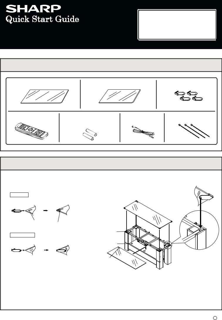
MODEL
AN-GR500H
HOME CINEMA RACK SYSTEM
This quick Start Guide will help you to correctly install and operate your system.
If you require any advice or assistance regarding your Sharp product, please visit our web-site www.sharp.co.uk/customersupport.aspx Customers without internet access may telephone 0870 787 4837 during office hours (or (01) 843 4711 if telephoning from Ireland).
|
1 |
Accessories |
|||
|
Top glass x 1 |
Bottom glass x 1 |
Glass protector x 4 |
||
|
Remote control x 1 |
«AA» size battery |
FM aerial x 1 |
Adjustable nylon band x 3 |
|
|
(UM/SUM-3, R6, HP-7 or similar) |
||||
|
x 2 |
||||
|
2 |
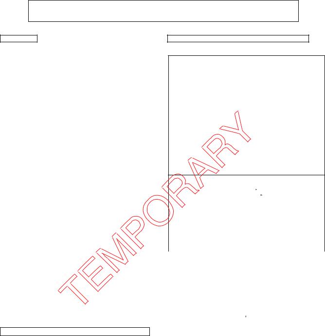
Installing the glass and the glass protector |
1.Fix the glass protector to the top glass at each corner.
Make sure the «TEMPERED» sticker on top of the glass is facing up.
TOP VIEW
2.Place the top glass on top of the frame.
Make sure all the glass protector guide is fitting to the frame hole.
“TEMPERED” sticker  Glass protector
Top glass
|
“TEMPERED” sticker |
Frame hole for |
|
the glass protector |
|
|
BOTTOM VIEW |
to fit in. |
|
Step 1 |
Step 2 |
Subwoofer box |
“TEMPERED” sticker
Notes:
 It is advisable for the top glass to be carried by 2 persons.
 Top glass with sticker on its surface, must face upwards.
 Metal frame must not be removed to ensure safety.
 The maximum load for the top glass on the unit is 100 kg.
 The glasses are made of reinforced glass, but dropping pointed objects on them or strongly hitting the surface may cause them to break.
 Top and bottom glass are not fastened to the unit. Always take care when transporting it, otherwise these parts may fall off and there is a risk of damage and injury.
Bottom
glass
3.Place the bottom glass on top of the subwoofer box.
Make sure the “TEMPERED” sticker on top of the glass is facing up.
TINSEA270AWZZ 08G R MW 1
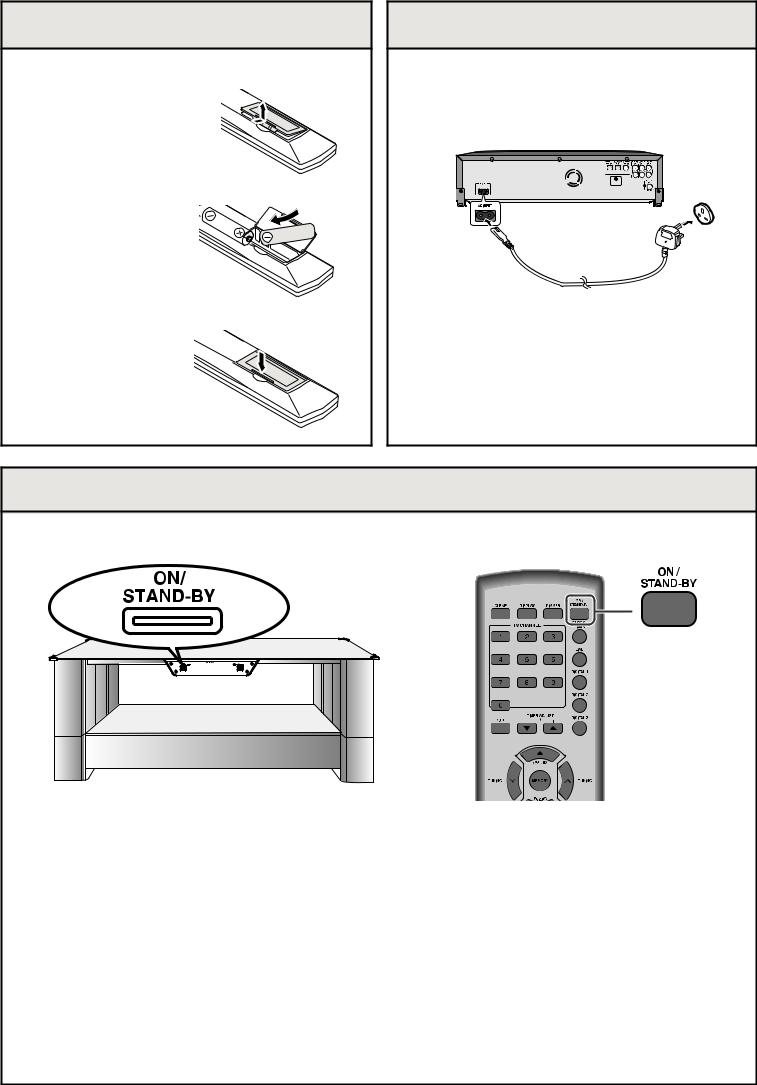
3 Remote control battery installation
Use 2 “AA” size batteries (UM/SUM-3, R6, HP-7 or similar).
1 Open the battery cover.
2 Insert the batteries as shown.
3 Close the cover.
4 Connecting the AC power lead
After checking all the connections have been made correctly, connect the AC power lead to the AC power input socket, then to the wall socket.
Wall socket
(AC 220 V- 240 V, 50 Hz)
Notes:
 Never use a power lead other than the one supplied. Otherwise, a malfunction or an accident may occur.
 Unplug the AC power lead from the wall socket if the unit will not be in use for a prolonged period of time.
5 To turn the power on
Press the ON/STAND-BY button.
If the power does not turn on, check whether the power lead is plugged in properly.
To set the unit to stand-by mode:
Press the ON/STAND-BY button again.
Note:
After the unit enters the power stand-by mode, wait a few seconds to turn on again
AN-GR500H


 SERVICE MANUAL
No. S7840ANR500HH
HOME CINEMA RACK SYSTEM


 MODEL AN-GR500H
[For Europe, U.K., Australia and New Zealand]
• In the interests of user-safety the set should be restored to its original condition and only parts identical to those specified be used.
CONTENTS
PRECAUTIONS FOR USING LEAD FREE SOLDER
|
CHAPTER 1. GENERAL DESCRIPTION |
||
|
[1] |
Specifications………………………………………… |
1-1 |
|
[2] |
Names Of Parts …………………………………….. |
1-2 |
|
CHAPTER 2. ADJUSTMENTS |
||
|
[1] Description Of Error Messages………………… |
2-1 |
|
|
[2] |
Test Mode …………………………………………….. |
2-2 |
|
[3] |
EEPROM Mode …………………………………….. |
2-2 |
|
[4] EEPROM List (Version: 02) …………………….. |
2-3 |
|
|
[5] KEY / LED Check Mode …………………………. |
2-5 |
|
|
[6] Quick Volume Change Mode …………………… |
2-5 |
|
|
[7] |
Tuner Test Mode ……………………………………. |
2-6 |
|
[8] ASPM Test Mode (For EU Destination) …….. |
2-6 |
|
|
CHAPTER 3. MECHANISM BLOCKS |
||
|
[1] |
Before Disassembly……………………………….. |
3-1 |
|
[2] |
Disassenbly Method ………………………………. |
3-2 |
|
CHAPTER 4. DIAGRAMS |
||
|
[1] |
Main Block Diagrams……………………………… |
4-1 |
|
[2] |
Power Block Diagrams …………………………… |
4-9 |
|
[3] |
Display Block Diagrams …………………………. |
4-11 |
|
[4] |
Amplifier Block Diagram………………………… |
4-13 |
|
[5] |
Subwoofer Block Diagram …………………….. |
4-15 |
CHAPTER 5. CIRCUIT DESCRIPTION
[1]To Check And Cancel Protect Circuit
|
Detection Line ……………………………………….. |
5-1 |
[2]Failure Detection Identification Using
|
STANDBY LED………………………………………. |
5-2 |
|
|
[3] Waveforms Of Subwoofer Circuit ……………… |
5-3 |
|
|
[4] |
Voltage …………………………………………………. |
5-4 |
|
CHAPTER 6. CIRCUIT SCHEMATICS AND PARTS |
||
|
LAYOUT |
||
|
[1] Notes On Schematic Diagram………………….. |
6-1 |
|
|
[2] Types Of Transistor And LED…………………… |
6-1 |
|
|
[3] |
Schematic Diagram ………………………………… |
6-2 |
|
[4] Charts Of Connecting Wires…………………… |
6-18 |
|
|
[5] Wiring Side Of PWB ……………………………… |
6-20 |
|
|
CHAPTER 7. OTHERS |
||
|
[1] Function Table Of IC……………………………….. |
7-1 |
|
|
[2] |
FL Display …………………………………………… |
7-12 |
PARTS GUIDE
Parts marked with »  » are important for maintaining the safety of the set. Be sure to replace these parts with specified ones for maintaining the safety and performance of the set.
This document has been published to be used SHARP CORPORATION for after sales service only.
The contents are subject to change without notice.
AN-GR500H
MXLESAervuardi-MP150kioceet anual
PRECAUTIONS FOR USING LEAD-FREE SOLDER
1. Employing lead-free solder
«MAIN, POWER, DISPLAY, INTERFACE, AMPLIFIER, SUBWOOFER PWB» of this model employs lead-free solder. The LF symbol indicates lead-free solder, and is attached on the PWB and service manuals. The alphabetical character following LF shows the type of lead-free solder.
Example:
Indicates lead-free solder of tin, silver and copper.
2.Using lead-free wire solder
When fixing the PWB soldered with the lead-free solder, apply lead-free wire solder. Repairing with conventional lead wire solder may cause damage or accident due to cracks.
As the melting point of lead-free solder (Sn-Ag-Cu) is higher than the lead wire solder by 40 C, we recommend you to use a dedicated soldering bit, if you are not familiar with how to obtain lead-free wire solder or soldering bit, contact our service station or service branch in your area.
3.Soldering
As the melting point of lead-free solder (Sn-Ag-Cu) is about 220 C which is higher than the conventional lead solder by 40  C, and as it has poor solder wettability, you may be apt to keep the soldering bit in contact with the PWB for extended period of time. However, since the land may be peeled off or the maximum heat-resistance temperature of parts may be exceeded, remove the bit from the PWB as soon as you confirm the steady soldering condition.
Lead-free solder contains more tin, and the end of the soldering bit may be easily corrected. Make sure to turn on and off the power of the bit as required.
If a different type of solder stays on the tip of the soldering bit, it is alloyed with lead-free solder. Clean the bit after every use of it.
When the tip of the soldering bit is blackened during use, file it with steel wool or fine sandpaper. Be careful when replacing parts with polarity indication on the PWB silk.
Lead-free wire solder for servicing
|
Ref No. |
Parts No. |
Description |
|
PWB-A |
92LPWB7358MANS |
MAIN |
|
PWB-B |
92LPWB7358PWRS |
POWER(B1), DISPLAY(B2), INTERFACE(B3) |
|
PWB-C |
92LPWB7358AMPS |
AMPLIFIER |
|
PWB-D |
92LPWB7358SWFS |
SUBWOOFER |
– i –
AN-GR500H
CHAPTER 1: GENERAL DESCRIPTION
[1] Specifications
FOR A COMPLETE DESCRIPTION OF THE OPERATION OF THIS UNIT, PLEASE REFER TO THE OPERATION MANUAL.
AN-GR500H
• Main unit
|
Amplifier section |
||
|
Power source |
AC 220 V — 240 V ~ 50 Hz |
|
|
Power |
Power on: 63 W |
|
|
consumption |
Power stand-by: 0.6 W |
|
|
Amplification |
Front speaker: Pulse width modulation |
|
|
system |
Subwoofer: Pulse width modulation |
|
|
Frequency range |
FM: 87.5 — 108 MHz |
|
|
Output power |
Front speaker: |
|
|
MPO: 100W (50W + 50W) (DIN 45 324) |
||
|
RMS: 100W (50W + 50W) (DIN 45 324) |
||
|
RMS: 90W (45W + 45W) (DIN 45 500) |
||
|
Subwoofer: |
||
|
MPO: 100W (DIN 45 324) |
||
|
RMS: 100W (DIN 45 324) |
||
|
RMS: 90W (DIN 45 500) |
||
|
Audio input |
Optical digital input (DIGITAL 1/2): Square type x 2 |
|
|
terminals |
Coaxial digital input (DIGITAL 3): RCA type x 1 |
|
|
Analog input (LINE 1): RCA type x 1 pair (L/R) |
||
|
Analog input (LINE 2): RCA type x 1 pair (L/R) |
||
|
Analog input (LINE 3): RCA type x 1 pair (L/R) |
||
|
Front speaker section |
||
|
Type |
2-way type speaker system (Magnetic shield) |
|
|
2.5 cm (1″) Tweeter x 2 |
||
|
8 cm (3-1/8″) Woofer x 2 |
||
|
Impedance |
6 ohms |
|
|
General |
||
|
Dimensions |
Width: 1105 mm (43-1/2″) |
|
|
Height: 482 mm (19″) |
||
|
Depth: 387 mm (15-1/4″) |
||
|
Weight |
38.25 kg (84.33 lbs.) |
|
|
Glass on top of |
The maximum load/weight:100kg |
|
|
unit |
||
|
• Subwoofer |
||
|
Type |
Subwoofer system (Magnetic shield) |
|
|
20 cm (8″) Subwoofer |
||
|
Maximum input |
100 W |
|
|
power |
||
|
Impedance |
12 ohms |
|
|
• Remote control |
||
|
Power source |
DC 3V [«AA» size (UM/SUM-3, R6, HP-7 |
|
|
or similar) battery x 2] |
||
AN-GR500H for U.K., Australia and New Zealand
• Main unit
Amplifier section
|
Power source |
AC 220 V — 240 V ~ 50 Hz |
|
Power |
Power on: 63 W |
|
consumption |
Power stand-by: 0.6 W |
|
Amplification |
Front speaker: Pulse with modulation |
|
system |
Subwoofer: Pulse with modulation |
|
Frequency range |
FM : 87.5 — 108 MHz |
|
Output power |
Front speaker: |
|
MPO: 100W (50W + 50W) (T.H.D. 10%) |
|
|
RMS: 100W (50W + 50W) (T.H.D. 10%) |
|
|
RMS: 90W (45W + 45W) (T.H.D. 0.9%) |
|
|
Subwoofer: |
|
|
MPO: 100W (T.H.D. 10%) |
|
|
RMS: 100W (T.H.D. 10%) |
|
|
RMS: 90W (T.H.D. 0.9%) |
|
|
Audio input |
Optical digital input (DIGITAL 1/2): Square type x 2 |
|
terminals |
Coaxial digital input (DIGITAL 3): RCA type x 1 |
|
Analog input (LINE 1): RCA type x 1 pair (L/R) |
|
|
Analog input (LINE 2): RCA type x 1 pair (L/R) |
|
|
Analog input (LINE 3): RCA type x 1 pair (L/R) |
|
Front speaker section
|
Type |
2-way type speaker system (Magnetic shield) |
|||||||
|
2.5 cm (1″) Tweeter |
2 |
|||||||
|
8 cm (3 — 1/8″) Woofer |
2 |
|||||||
|
Impedance |
6 ohms |
|||||||
|
General |
||||||||
|
Dimensions |
Width: 1105 mm (43-1/2″) |
|||||||
|
Height: 482 mm (19″) |
||||||||
|
Depth: 387 mm (15-1/4″) |
||||||||
|
Weight |
38.25 kg (84.33 lbs.) |
|||||||
|
Glass on top of |
The maximum load/weight: 100 kg |
|||||||
|
unit |
||||||||
|
• Subwoofer |
||||||||
|
Type |
Subwoofer system (Magnetic shield) |
|||||||
|
20 cm (8″) Subwoofer |
||||||||
|
Maximum input |
100 W |
|||||||
|
power |
||||||||
|
Impedance |
12 ohms |
|||||||
|
• Remote control |
||||||||
|
Power source |
DC 3V [«AA» size (UM/SUM-3, R6, HP-7 or |
|||||||
|
similar) battery |
2] |
|||||||
Specifications for this model are subject to change without prior notice.
1 – 1
AN-GR500H
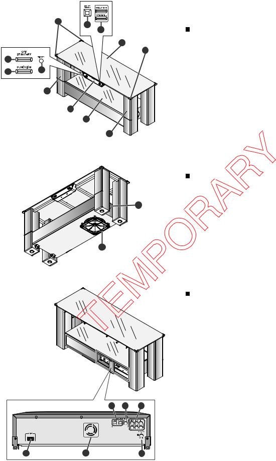
[2] Names Of Parts
|
11 |
8 |
||||
|
Main Unit (front panel) |
|||||
|
9 |
|||||
|
10 |
1. On/Stand-by Button |
||||
|
2. Function Button |
|||||
|
11 |
|||||
|
3. Timer Indicator |
|||||
|
1 |
|||||
|
4. Left Front Speakers |
|||||
|
2 |
3 |
5. Display |
|||
|
6. Bottom glass |
|||||
|
7. Right Front Speakers |
|||||
|
4 |
8. Remote Sensor |
||||
|
9. Volume Up and Down Buttons |
|||||
|
5 |
10. Top glass |
||||
|
11. Glass protector |
|||||
6
7
Main unit (bottom panel)
1. Subwoofer
2. Bass Reflex Duct
 2
2
1
Main unit (rear panel)
1. Optical Digital Audio Input Sockets
2. Coaxial Digital Audio Input Socket
3. Audio Line Input Sockets
4. AC Power Input Socket
5. Cooling Fan
6. FM 75 Ohms Aerial Socket
1 – 2
AN-GR500H
|
9 |
Display |
|||||||||||||||
|
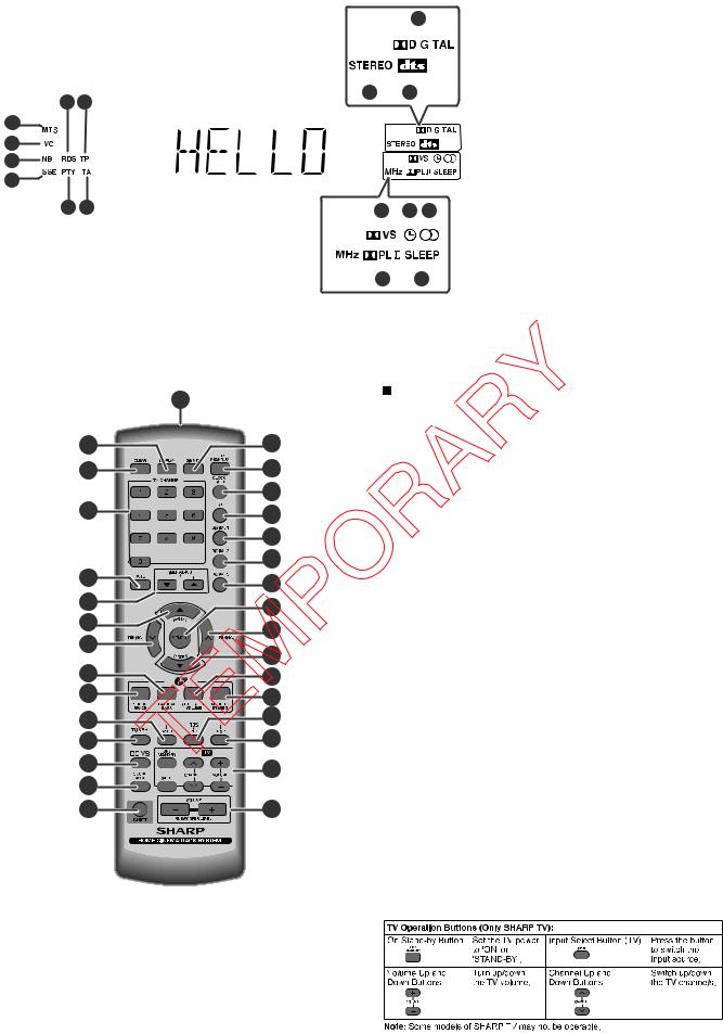
1. Mono to Stereo indicator |
||||||||||||||||
|
2. Intelligent Volume indicator |
||||||||||||||||
|
3. Natural Bass indicator |
||||||||||||||||
|
4. Sound Space indicator |
||||||||||||||||
|
10 |
11 |
|||||||||||||||
|
7 |
8 |
5. Dynamic PTY indicator |
||||||||||||||
|
1 |
6. Traffic Announcement indicator |
|||||||||||||||
|
2 |
7. RDS indicator |
|||||||||||||||
|
8. Traffic Programme indicator |
||||||||||||||||
|
3 |
||||||||||||||||
|
9. Dolby Digital Signal indicator |
||||||||||||||||
|
4 |
10. FM Stereo Mode indicator |
|||||||||||||||
|
5 |
6 |
11. DTS Signal indicator |
||||||||||||||
|
12 |
13 14 |
|||||||||||||||
|
12. Dolby Virtual Sound indicator |
||||||||||||||||
|
13. Timer indicator |
||||||||||||||||
|
14. FM Stereo Receiving indicator |
||||||||||||||||
|
15. Dolby Prologic II indicator |
||||||||||||||||
|
16. Sleep indicator |
||||||||||||||||
|
15 |
16 |
|
1 |
Remote control |
||
|
1. Remote Control Transmitter |
|||
|
16 |
2. Display Button |
||
|
2 |
3. Clear Button |
||
|
3 |
17 |
4. TV Channel Number Button |
|
|
5. Mute Button |
|||
|
18 |
6. Timer Adjust Up or Down Button |
||
|
4 |
19 |
7. Preset Up Button |
|
|
8. Tuning Down Button |
|||
|
20 |
|||
|
9. Natural Bass Button |
|||
|
21 |
10. Sound Space Button |
||
|
5 |
22 |
11. RDS ASPM Button |
|
|
12. Tuner Button |
|||
|
6 |
|||
|
23 |
13. Dolby Virtual Speaker Button |
||
|
7 |
14. Sound Mode Button |
||
|
24 |
|||
|
8 |
15. Shift Button |
||
|
25 |
16. Dimmer Button |
||
|
9 |
17. ON/STAND-BY Button |
||
|
26 |
|||
|
18. Clock / Timer Button |
|||
|
10 |
27 |
19. Line Button |
|
|
11 |
28 |
20. Digital 1 Button |
|
|
21. Digital 2 Button |
|||
|
12 |
29 |
||
|
22. Digital 3 Button |
|||
|
13 |
30 |
23. Memory Button |
|
|
14 |
24. Tuning Up Button |
||
|
25. Preset Down Button |
|||
|
15 |
31 |
||
|
26. Intelligent Volume Button |
|||
|
27. Mono to Stereo Button |
|||
|
28. RDS PTY Button |
|||
|
29. RDS Display Button |
|||
|
30. TV Operation Buttons |
|||
|
31. Volume Up or Down Buttons |
1 – 3

AN-GR500H
CHAPTER 2. ADJUSTMENTS
[1] Description Of Error Messages
|
Error message |
Cause |
Solution |
|
“ERR 01” |
• Rotation stop of the fan motor |
• Check if the fan motor cord is inserted |
|
(Appears for 2 seconds and then the system |
properly and the fan motor is not locked. |
|
|
goes standby.) |
||
|
“ERR 02” |
• Error in the ICM6 (CS49510) control |
• Unplug the AC power cord and turn on |
|
(When this error is not detected, the initial |
power again. |
|
|
display appears.) |
• Check the line connected between ICM6 |
|
|
and ICM7. |
||
|
“ERR 03” |
• Internal communication error of the system |
• Unplug the AC power cord and turn on |
|
(When this error is not detected, the initial |
[ICA1 (WM8775) or ICM3 (CS8416CN)] |
power again. |
|
display appears.) |
• Check the line connected among ICA1, |
|
|
ICM3, ICM8 and ICM7. |
||
|
“ERR 07” |
• Internal communication error of the system |
• Unplug the AC power cord and turn on |
|
(When this error is not detected, the initial |
[ICM10 (LC750512)] |
power again. |
|
display appears.) |
• Check the line connected between ICM10 |
|
|
and ICM7. |
||
|
“ERR 80” |
• Internal data read access error of ICM8 |
• Check EEPROM data. |
|
(When this error is not detected, the initial |
(CAT24WC05YI) |
• Replace EEPROM IC (ICM8). |
|
display appears.) |
||
* For other error messages using STANDBY LED, refer to the corresponding pages.
2 – 1
![]()
[2] Test Mode
1. Entering the test mode
In the AC OFF state, hold down the “FUNCTION” key and press the POWER key. Then switch on AC to enter the test mode route state.
* Be sure to follow the above procedure to enter the test mode.
2. Exiting the test mode
In the test mode route state, press the POWER key to turn off the system and exit the test mode.
3. Operation
(Test mode start-up operation)
↓
GR8529BH
↓ (POWER key)
GOOD BYE
Version Display (example version date is 29/05/2008)
Display “GOOD BYE”
(as in the case of the user mode)
[3] EEPROM Mode
When replacing EEPROM IC, necessary data are not recorded inside; “Protect area read error” (“ERR 80”) occurs.
To avoid this state, write the data into the corresponding device.
1.Enter the test mode and check set data values of each address according to the EEPROM set data table on the right.
If necessary, change the set data values.
NOTE: (Data are written into EEPROM in the procedure 4 below.)
(Do not stop power supply to the product)
AN-GR500H
4. Remote control key operation
Key operation is described by using the names of the main unit keys. For remote control key operation, each test can be enter directly as follow.
*However, remote control keys are unavailable for starting the test mode.
|
Remote Control Key |
Test Mode |
|
MUTE key |
Volume Test |
|
DVS key |
Key Test |
|
SOUND MODE key |
EEPROM Mode Test |
|
TUNER key |
Tuner Test |
|
ASPM key |
ASPM Test |
* Remote control keys are unavailable for starting the test mode.
GR8529BH
↓
EEP TEST
↓
EEP 025A
EEP 025B
↑ ↓
EEP 025C
EEP 03FE
↑ ↓
EEP 03FF
Test mode route state
(Example Micom version date 29/5/2008)
Mode menu “EEPROM“
(VOLUME + key): EEPROM mode start-up
EEPROM address display (25Ah) (VOLUME + key): Address increment
EEPROM address display (25Bh)
(Input select key)
←
→
At each address
(Input select key)
EEPROM address display (3FF h)
|
EEP 005A |
Set data value display |
↑ ↓ (2 Hz flasing)
(Set value change by VOLUME +/– keys)
2.Exiting the EEPROM mode from the address value display state. (Press the POWER key once in the address value display state.) (The product enters the test mode route state.)
3.Exiting the test mode
(Press the POWER key once in the test mode route state.)
(Then the data are written into EEPROM. After the write operation, the product enters the standby state.)
4.After checking that the product enters the standby state, stop power supply to the product.
(This operation initializes the error state.)
* Operation ends.
2 – 2

AN-GR500H
[4] EEPROM List (Version: 02) (1/2)
|
ADDRESS |
|||||||
|
HEX |
ITEM |
CODE |
ITEM |
CODE |
|||
|
025A |
602 |
PVER |
02h |
AUMD |
#REF! |
07h |
|
|
025C |
604 |
ITVL |
25h |
ITVC |
01h |
||
|
025E |
606 |
NBCF |
05h |
NBLV |
65h |
||
|
0260 |
608 |
INISW |
FFh |
CHECK-SUM |
67h |
||
|
0262 |
610 |
reserved |
FFh |
reserved |
FFh |
||
|
0264 |
612 |
reserved |
FFh |
reserved |
FFh |
||
|
0266 |
614 |
CHECK-SUM |
03h |
OFGA |
00h |
||
|
0268 |
616 |
OFBS |
00h |
OFTR |
00h |
||
|
026A |
618 |
reserved |
FFh |
CIGA |
02h |
||
|
026C |
620 |
CIBS |
00h |
CITR |
03h |
||
|
026E |
622 |
reserved |
FFh |
ANGA |
00h |
||
|
0270 |
624 |
ANBS |
0Bh |
ANTR |
05h |
||
|
0272 |
626 |
reserved |
FFh |
SOGA |
02h |
||
|
0274 |
628 |
SOBS |
00h |
SOTR |
03h |
||
|
0276 |
630 |
reserved |
FFh |
SPGA |
02h |
||
|
0278 |
632 |
SPBS |
00h |
SPTR |
03h |
||
|
027A |
634 |
reserved |
FFh |
LAGA |
02h |
||
|
027C |
636 |
LABS |
00h |
LATR |
03h |
||
|
027E |
638 |
reserved |
FFh |
reserved |
FFh |
||
|
0280 |
640 |
CHECK-SUM |
E2h |
E48AU |
3Ch |
||
|
0282 |
642 |
E48AM |
39h |
E48AL |
83h |
||
|
0284 |
644 |
E48BU |
A0h |
E48BM |
A3h |
||
|
0286 |
646 |
E48BL |
60h |
E48CU |
29h |
||
|
0288 |
648 |
E48CM |
EBh |
E48CL |
F2h |
||
|
028A |
650 |
E48DU |
5Fh |
E48DM |
5Ch |
||
|
028C |
652 |
E48DL |
9Fh |
E48EU |
D9h |
||
|
028E |
654 |
E48EM |
DAh |
E48EL |
8Ah |
||
|
0290 |
656 |
E44AU |
3Bh |
E44AM |
F9h |
||
|
0292 |
658 |
E44AL |
E1h |
E44BU |
A3h |
||
|
0294 |
660 |
E44BM |
71h |
E44BL |
6Dh |
||
|
0296 |
662 |
E44CU |
28h |
E44CM |
77h |
||
|
0298 |
664 |
E44CL |
D4h |
E44DU |
5Ch |
||
|
029A |
666 |
E44DM |
8Eh |
E44DL |
93h |
||
|
029C |
668 |
E44EU |
DBh |
E44EM |
8Eh |
||
|
029E |
670 |
E44EL |
49h |
E32AU |
3Ah |
||
|
02A0 |
672 |
E32AM |
F6h |
E32AL |
2Eh |
||
|
02A2 |
674 |
E32BU |
B0h |
E32BM |
47h |
||
|
02A4 |
676 |
E32BL |
CFh |
E32CU |
22h |
||
|
02A6 |
678 |
E32CM |
89h |
E32CL |
1Bh |
||
|
02A8 |
680 |
E32DU |
4Fh |
E32DM |
B8h |
||
|
02AA |
682 |
E32DL |
30h |
E32EU |
E2h |
||
|
02AC |
684 |
E32EM |
80h |
E32EL |
E6h |
||
|
02AE |
686 |
reserved |
FFh |
CHECK-SUM |
27h |
||
|
02B0 |
688 |
GPDOU |
0Fh |
GPDO2 |
11h |
|
ADDRESS |
|||||||
|
HEX |
ITEM |
CODE |
ITEM |
CODE |
|||
|
02B2 |
690 |
GPDO3 |
B6h |
48 |
9Dh |
||
|
02B4 |
692 |
GPDFH |
05h |
50 |
0Ch |
||
|
02B6 |
694 |
GPDF3 |
33h |
52 |
5Dh |
||
|
02B8 |
696 |
GADOH |
14h |
54 |
18h |
||
|
02BA |
698 |
GADO3 |
57h |
56 |
E9h |
||
|
02BC |
700 |
GADFH |
0Fh |
58 |
F6h |
||
|
02BE |
702 |
GADF3 |
4Ch |
60 |
16h |
||
|
02C0 |
704 |
GDDOH |
08h |
62 |
00h |
||
|
02C2 |
706 |
GDDO3 |
00h |
64 |
00h |
||
|
02C4 |
708 |
GDDFH |
0Bh |
66 |
4Ch |
||
|
02C6 |
710 |
GDDF3 |
E0h |
68 |
7Bh |
||
|
02C8 |
712 |
GCDOH |
09h |
70 |
82h |
||
|
02CA |
714 |
GCDO3 |
0Dh |
72 |
74h |
||
|
02CC |
716 |
GCDFH |
0Bh |
74 |
4Ch |
||
|
02CE |
718 |
GCDF3 |
E0h |
80 |
7Bh |
||
|
02D0 |
720 |
GaDOH |
14h |
82 |
18h |
||
|
02D2 |
722 |
GaDO3 |
57h |
84 |
E9h |
||
|
02D4 |
724 |
GaDFH |
07h |
86 |
21h |
||
|
02D6 |
726 |
GaDF3 |
48h |
88 |
2Bh |
||
|
02D8 |
728 |
reserved |
2Bh |
90 |
9Ah |
||
|
02DA |
730 |
0 |
FFh |
92 |
FF |
||
|
02DC |
732 |
2 |
9Ah |
94 |
FF |
||
|
02DE |
734 |
4 |
FFh |
96 |
FF |
||
|
02E0 |
736 |
6 |
FF |
98 |
FF |
||
|
02E2 |
738 |
8 |
FF |
100 |
FF |
||
|
02E4 |
740 |
10 |
FF |
102 |
FF |
||
|
02E6 |
742 |
12 |
FF |
104 |
FF |
||
|
02E8 |
744 |
14 |
FF |
106 |
FF |
||
|
02EA |
746 |
16 |
FFh |
108 |
FFh |
||
|
02EC |
748 |
18 |
FFh |
110 |
FFh |
||
|
02EE |
750 |
20 |
FFh |
112 |
FFh |
||
|
02F0 |
752 |
22 |
FFh |
114 |
FFh |
||
|
02F2 |
754 |
24 |
FFh |
116 |
FFh |
||
|
02F4 |
756 |
26 |
FFh |
118 |
FFh |
||
|
02F6 |
758 |
28 |
FFh |
120 |
FFh |
||
|
02F8 |
760 |
30 |
FFh |
122 |
FFh |
||
|
02FA |
762 |
32 |
FFh |
124 |
FFh |
||
|
02FC |
764 |
34 |
FFh |
126 |
FFh |
||
|
02FE |
766 |
36 |
FFh |
128 |
FFh |
||
|
0300 |
768 |
38 |
FFh |
130 |
FFh |
||
|
0302 |
770 |
40 |
FFh |
132 |
FFh |
||
|
0304 |
772 |
42 |
FFh |
134 |
FFh |
||
|
0306 |
774 |
44 |
FFh |
136 |
FFh |
||
|
0308 |
776 |
46 |
FFh |
138 |
FFh |
|
ADDRESS |
|||||||
|
HEX |
ITEM |
CODE |
ITEM |
CODE |
|||
|
030A |
778 |
RM32 |
FFh |
RM33 |
FFh |
||
|
030C |
780 |
RM34 |
FFh |
RM35 |
FFh |
||
|
030E |
782 |
RM36 |
FFh |
RM37 |
FFh |
||
|
0310 |
784 |
RM38 |
FFh |
RM39 |
FFh |
||
|
0312 |
786 |
RM40 |
FFh |
RM41 |
FFh |
||
|
0314 |
788 |
RM42 |
FFh |
RM43 |
FFh |
||
|
0316 |
790 |
RM44 |
FFh |
RM45 |
FFh |
||
|
0318 |
792 |
RM46 |
FFh |
RM47 |
FFh |
||
|
031A |
794 |
RM48 |
FFh |
RM49 |
FFh |
||
|
031C |
796 |
RM50 |
FFh |
RM51 |
FFh |
||
|
031E |
798 |
RM52 |
FFh |
RM53 |
FFh |
||
|
0320 |
800 |
RM54 |
FFh |
RM55 |
FFh |
||
|
0322 |
802 |
RM56 |
FFh |
RM57 |
FFh |
||
|
0324 |
804 |
RM58 |
FFh |
RM59 |
FFh |
||
|
0326 |
806 |
RM60 |
FFh |
RM61 |
FFh |
||
|
0328 |
808 |
RM62 |
FFh |
RM63 |
FFh |
||
|
032A |
810 |
RM64 |
FFh |
RM65 |
FFh |
||
|
032C |
812 |
RM66 |
FFh |
RM67 |
FFh |
||
|
032E |
814 |
RM68 |
FFh |
RM69 |
FFh |
||
|
0330 |
816 |
RM70 |
FFh |
RM71 |
FFh |
|
ADDRESS |
|||||||
|
HEX |
ITEM |
CODE |
ITEM |
CODE |
|||
|
0332 |
818 |
RM72 |
FFh |
RM73 |
FFh |
||
|
0334 |
820 |
RM74 |
FFh |
RM75 |
FFh |
||
|
0336 |
822 |
RM76 |
FFh |
RM77 |
FFh |
||
|
0338 |
824 |
RM78 |
FFh |
RM79 |
FFh |
||
|
033A |
826 |
RM80 |
FFh |
RM81 |
FFh |
||
|
033C |
828 |
RM82 |
FFh |
RM83 |
FFh |
||
|
033E |
830 |
RM84 |
FFh |
RM85 |
FFh |
||
|
0340 |
832 |
RM86 |
FFh |
RM87 |
FFh |
||
|
0342 |
834 |
RM88 |
FFh |
RM89 |
FFh |
||
|
0344 |
836 |
RM90 |
FFh |
RM91 |
FFh |
||
|
0346 |
838 |
RM92 |
FFh |
RM93 |
FFh |
||
|
0348 |
840 |
RM94 |
FFh |
RM95 |
FFh |
||
|
034A |
842 |
RM96 |
FFh |
RM97 |
FFh |
||
|
034C |
844 |
RM98 |
FFh |
RM99 |
FFh |
||
|
034E |
846 |
RM100 |
FFh |
RM101 |
FFh |
||
|
0350 |
848 |
RM102 |
FFh |
RM103 |
FFh |
||
|
0352 |
850 |
RM104 |
FFh |
RM105 |
FFh |
||
|
0354 |
852 |
RM106 |
FFh |
RM107 |
FFh |
||
|
0356 |
854 |
RM108 |
FFh |
RM109 |
FFh |
||
|
0358 |
856 |
RM110 |
FFh |
CHECK-SUM |
EFh |
2 – 3

AN-GR500H
[4] EEPROM List (Version: 02) (2/2)
|
ADDRESS |
|||||||
|
HEX |
ITEM |
CODE |
ITEM |
CODE |
|||
|
035A |
858 |
RM56 |
FFh |
RM57 |
FFh |
||
|
035C |
860 |
RM58 |
FFh |
RM59 |
FFh |
||
|
035E |
862 |
RM60 |
FFh |
RM61 |
FFh |
||
|
0360 |
864 |
RM62 |
FFh |
RM63 |
FFh |
||
|
0362 |
866 |
RM64 |
FFh |
RM65 |
FFh |
||
|
0364 |
868 |
RM66 |
FFh |
RM67 |
FFh |
||
|
0366 |
870 |
RM68 |
FFh |
RM69 |
FFh |
||
|
0368 |
872 |
RM70 |
FFh |
RM71 |
FFh |
||
|
036A |
874 |
RM72 |
FFh |
RM73 |
FFh |
||
|
036C |
876 |
RM74 |
FFh |
RM75 |
FFh |
||
|
036E |
878 |
RM76 |
FFh |
RM77 |
FFh |
||
|
0370 |
880 |
RM78 |
FFh |
RM79 |
FFh |
||
|
0372 |
882 |
RM80 |
FFh |
RM81 |
FFh |
||
|
0374 |
884 |
RM82 |
FFh |
RM83 |
FFh |
||
|
0376 |
886 |
RM84 |
FFh |
RM85 |
FFh |
||
|
0378 |
888 |
RM86 |
FFh |
RM87 |
FFh |
||
|
037A |
890 |
RM88 |
FFh |
RM89 |
FFh |
||
|
037C |
892 |
RM90 |
FFh |
RM91 |
FFh |
||
|
037E |
894 |
RM92 |
FFh |
RM93 |
FFh |
||
|
0380 |
896 |
RM94 |
FFh |
RM95 |
FFh |
||
|
ADDRESS |
|||||||
|
HEX |
ITEM |
CODE |
ITEM |
CODE |
|||
|
03AA |
938 |
RM80 |
FFh |
RM81 |
FFh |
||
|
03AC |
940 |
RM82 |
FFh |
RM83 |
FFh |
||
|
03AE |
942 |
RM84 |
FFh |
RM85 |
FFh |
||
|
03B0 |
944 |
RM86 |
FFh |
RM87 |
FFh |
||
|
03B2 |
946 |
RM88 |
FFh |
RM89 |
FFh |
||
|
03B4 |
948 |
RM90 |
FFh |
RM91 |
FFh |
||
|
03B6 |
950 |
RM92 |
FFh |
RM93 |
FFh |
||
|
03B8 |
952 |
RM94 |
FFh |
RM95 |
FFh |
||
|
03BA |
954 |
RM96 |
FFh |
RM97 |
FFh |
||
|
03BC |
956 |
RM98 |
FFh |
RM99 |
FFh |
||
|
03BE |
958 |
RM100 |
FFh |
RM101 |
FFh |
||
|
03C0 |
960 |
RM102 |
FFh |
RM103 |
FFh |
||
|
03C2 |
962 |
RM104 |
FFh |
RM105 |
FFh |
||
|
03C4 |
964 |
RM106 |
FFh |
RM107 |
FFh |
||
|
03C6 |
966 |
RM108 |
FFh |
RM109 |
FFh |
||
|
03C8 |
968 |
RM110 |
FFh |
RM111 |
FFh |
||
|
03CA |
970 |
RM112 |
FFh |
RM113 |
FFh |
||
|
03CC |
972 |
RM114 |
FFh |
RM115 |
FFh |
||
|
03CE |
974 |
RM116 |
FFh |
RM117 |
FFh |
||
|
03D0 |
976 |
RM118 |
FFh |
RM119 |
FFh |
||
|
ADDRESS |
|||||||
|
HEX |
ITEM |
CODE |
ITEM |
CODE |
|||
|
03FA |
1018 |
RM104 |
FFh |
RM105 |
FFh |
||
|
03FC |
1020 |
RM106 |
FFh |
RM107 |
FFh |
||
|
03FE |
1022 |
RM108 |
FFh |
RM109 |
FFh |
|
ADDRESS |
|||||||
|
HEX |
ITEM |
CODE |
ITEM |
CODE |
|||
|
0382 |
898 |
RM96 |
FFh |
RM97 |
FFh |
||
|
0384 |
900 |
RM98 |
FFh |
RM99 |
FFh |
||
|
0386 |
902 |
RM100 |
FFh |
RM101 |
FFh |
||
|
0388 |
904 |
RM102 |
FFh |
RM103 |
FFh |
||
|
038A |
906 |
RM104 |
FFh |
RM105 |
FFh |
||
|
038C |
908 |
RM106 |
FFh |
RM107 |
FFh |
||
|
038E |
910 |
RM108 |
FFh |
RM109 |
FFh |
||
|
0390 |
912 |
RM110 |
FFh |
RM111 |
FFh |
||
|
0392 |
914 |
RM112 |
FFh |
RM113 |
FFh |
||
|
0394 |
916 |
RM114 |
FFh |
RM115 |
FFh |
||
|
0396 |
918 |
RM116 |
FFh |
RM117 |
FFh |
||
|
0398 |
920 |
RM118 |
FFh |
RM119 |
FFh |
||
|
039A |
922 |
RM120 |
FFh |
RM121 |
FFh |
||
|
039C |
924 |
RM122 |
FFh |
RM123 |
FFh |
||
|
039E |
926 |
RM124 |
FFh |
RM125 |
FFh |
||
|
03A0 |
928 |
RM126 |
FFh |
RM127 |
FFh |
||
|
03A2 |
930 |
RM128 |
FFh |
RM129 |
FFh |
||
|
03A4 |
932 |
RM130 |
FFh |
RM131 |
FFh |
||
|
03A6 |
934 |
RM132 |
FFh |
RM133 |
FFh |
||
|
03A8 |
936 |
RM134 |
FFh |
0 |
0 |
||
|
ADDRESS |
|||||||
|
HEX |
ITEM |
CODE |
ITEM |
CODE |
|||
|
03D2 |
978 |
RM120 |
FFh |
RM121 |
FFh |
||
|
03D4 |
980 |
RM122 |
FFh |
RM123 |
FFh |
||
|
03D6 |
982 |
RM124 |
FFh |
RM125 |
FFh |
||
|
03D8 |
984 |
RM126 |
FFh |
RM127 |
FFh |
||
|
03DA |
986 |
RM128 |
FFh |
RM129 |
FFh |
||
|
03DC |
988 |
RM130 |
FFh |
RM131 |
FFh |
||
|
03DE |
990 |
RM132 |
FFh |
RM133 |
FFh |
||
|
03E0 |
992 |
RM134 |
FFh |
RM135 |
FFh |
||
|
03E2 |
994 |
RM136 |
FFh |
RM137 |
FFh |
||
|
03E4 |
996 |
RM138 |
FFh |
RM139 |
FFh |
||
|
03E6 |
998 |
RM140 |
FFh |
RM141 |
FFh |
||
|
03E8 |
1000 |
RM142 |
FFh |
RM143 |
FFh |
||
|
03EA |
1002 |
RM144 |
FFh |
RM145 |
FFh |
||
|
03EC |
1004 |
RM146 |
FFh |
RM147 |
FFh |
||
|
03EE |
1006 |
RM148 |
FFh |
RM149 |
FFh |
||
|
03F0 |
1008 |
RM150 |
FFh |
RM151 |
FFh |
||
|
03F2 |
1010 |
RM152 |
FFh |
RM153 |
FFh |
||
|
03F4 |
1012 |
RM154 |
FFh |
RM155 |
FFh |
||
|
03F6 |
1014 |
RM156 |
FFh |
RM157 |
FFh |
||
|
03F8 |
1016 |
RM158 |
FFh |
0 |
0 |
NOTES:
(1)Use an attached HEX format file for setup of data to EEPROM writer.
(2)EEPROM currently used for this model is made in CATALYST. It is CAT24WC05YI.
2 – 4

AN-GR500H
[5] KEY / LED Check Mode
Display of 7-segment LED and each single LED
|
Transition during start-up |
|||
|
Test mode route state |
|||
|
GR8529BH |
|||
|
(Input select key) |
|||
|
↓ |
|||
|
KEY TEST |
Using FUNCTION key select “KEY TEST” |
||
|
Press Volume (–) / (+) key to enter KEY TEST |
|||
|
Press key according to below check key |
|||
|
response or LED light-up table |
|||
↓
|
** |
KEY |
FL DISPLAY |
||||
|
FUNCTION + VOLUME (–) |
FL all light-up |
|||||
|
LED light-up |
||||||
|
FUNCTION |
KEY 1-1 |
|||||
|
VOLUME + |
KEY 1-2 |
|||||
|
VOLUME – |
KEY 1-3 |
|||||
|
Press POWER key to return to Test Mode route state. |
||||||
|
[6] Quick Volume Change Mode |
||||||
|
Purpose |
||||||
|
The purpose of this mode is inspection time shortening in the |
||||||
|
production. |
||||||
|
This mode is the same as the USER MODE except for the volume |
||||||
|
operation. |
||||||
|
Volume operation in this mode becomes a change in a step only to |
||||||
|
the necessary position in inspection process. |
||||||
|
The specification of operation |
||||||
|
Main volume operation at QUICK VOL CHANGE MODE |
||||||
|
Only the following position of volume can be set up in this mode. |
||||||
|
VOLUME 0 |
||||||
|
(VOL–) ↑ ↓ (VOL+) |
||||||
|
VOLUME 1 |
||||||
|
(VOL–) ↑ ↓ (VOL+) |
||||||
|
VOLUME 10 |
||||||
|
(VOL–) ↑ ↓ (VOL+) |
||||||
|
VOLUME 20 |
||||||
|
(default value at QUICK VOL CHANGE MODE start) |
||||||
|
(VOL–) ↑ ↓ (VOL+) |
||||||
|
VOLUME 30 |
||||||
|
(VOL–) ↑ ↓ (VOL+) |
||||||
|
VOLUME 40 |
||||||
NOTES:
(1)About operation specification of «VOL +/– key».
(2)A difference from this mode and the user mode is only a possible volume steps and initial value after the mode start.
2 – 5

[7] Tuner Test Mode
Outline
This Test Mode control are same with Normal Power-ON, only Power-ON in TUNER function.
After Power-ON the operation and display are same but the TUNER preset already memory as table below.
TEST Mode Operation
Set will Power-ON same process like user Power-ON, but direct to TUNER Function Preset No. 1 of table below.
Set Preset Memory will be set as below table.
|
No. |
P1 |
87.50M |
|
|
P2 |
108.00M |
||
|
Memory |
|||
|
P3 |
90.00M |
||
|
Preset |
|||
|
P4 |
106.00M |
||
|
P5 |
98.00M |
||
SPAN 50K/9K
Key operation after Power ON are same with User Power-ON.
*When Test Mode end, Tuner Preset Memory will be initialize. Others Memory initialize is not neccesry.
[8] ASPM Test Mode (For EU Destination)
Outline
At Tuner RDS ASPM operation need to be confirm for EU(H) model only.
Power-ON in TUNER function, and scanning frequency from 105.00MHz — 108.00MHz.
And RDS station Preset Memory maximum 3 station.
TEST Mode Operation
Power ON in TUNER Function 106.50MHz FM Stereo Band. At same time Only Preset No. ch1 — ch3 leave blank and all ch4 — ch40 memory at 87.50MHz FM Stereo Band.
With the press of ASPM key, ASPM operation will start at 105.00MHz frequency.
If RDS station received Preset will memory from ch1. (There is no need to memory PS name in ASPM Test Mode. If preset change during Test Mode Frequency will be display first)
Scan will stop after reach frequency 108.00MHz, and return to frequency 106.50MHz FM Stereo.
To confirm Memory content display will show Preset Number and frequency for ch1until ch3. After display are confirmed frequency will return to 106.50MHz FM STEREO. (Display method same with Tuner display during Normal POWER ON.)
If ASPM key is press again, ASPM operation will start from 2 untill
5.
While scanning if 3 station memorized, Scanning will stop and operation 4 and 5 will take place.
Afterward, even if ASPM key input detect ASPM operation will not be execute. «__END__» displayed and operation canceled.
AN-GR500H
Additional
Other then above, operation for ASPM are same with User operation. So, when 1st time scan with same PI code Station with most strong signal will be memory and will not be memory many time. For 2nd and more station with same frequency will not be memory.
But, if different station with same PI code (same PI with different frequency station), station one with most strong signal will be memory.
So, station that already memorized before scan will be ignore. Therefore, even station with same same PI code after 3 times ASPM scan, It is possible that, 3 station will be memorized in Signal Strong order.
After Test Mode end only Tuner preset memory will be reset and set to default. Ohers Memory, no need to be initialize.
2 – 6
AN-GR500H
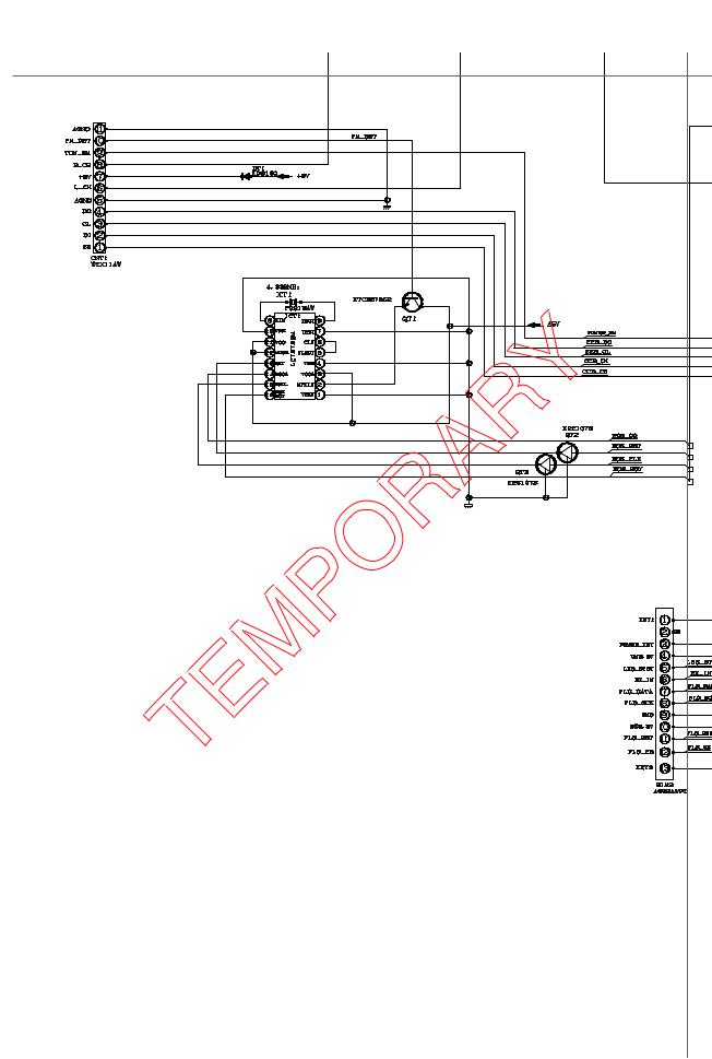
CHAPTER 4. DIAGRAMS
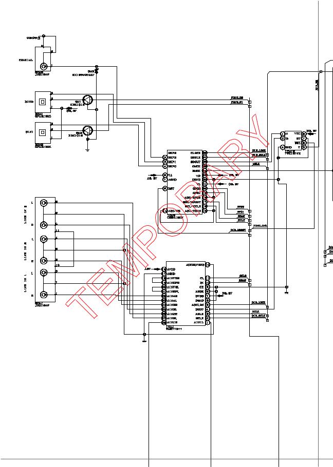
[1] Main Block Diagrams
Figure 4-1: BLOCK DIAGRAM (1/8)
4 – 1
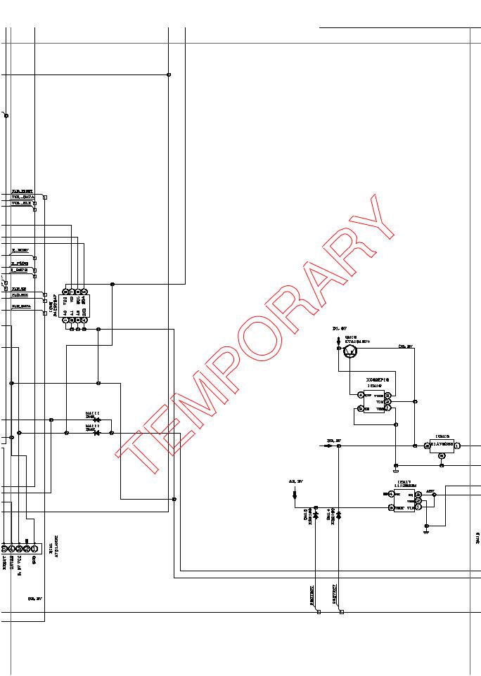
AN-GR500H
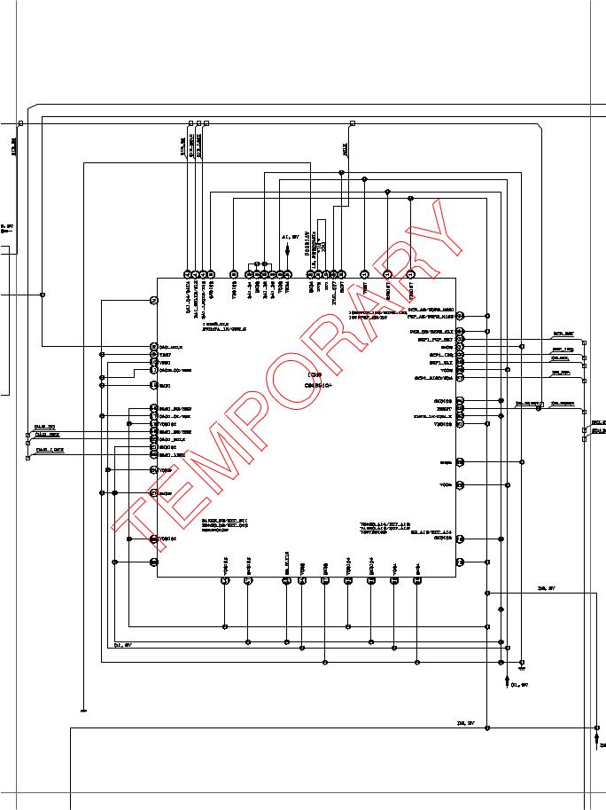
Figure 4-2: BLOCK DIAGRAM (2/8)
4 – 2
AN-GR500H
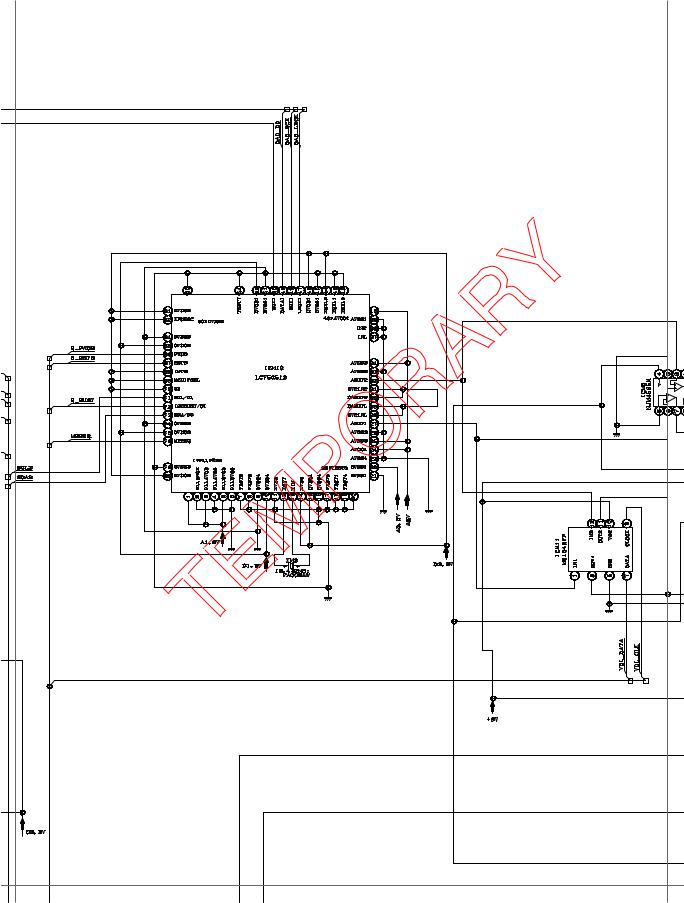
Figure 4-3: BLOCK DIAGRAM (3/8)
4 – 3
AN-GR500H
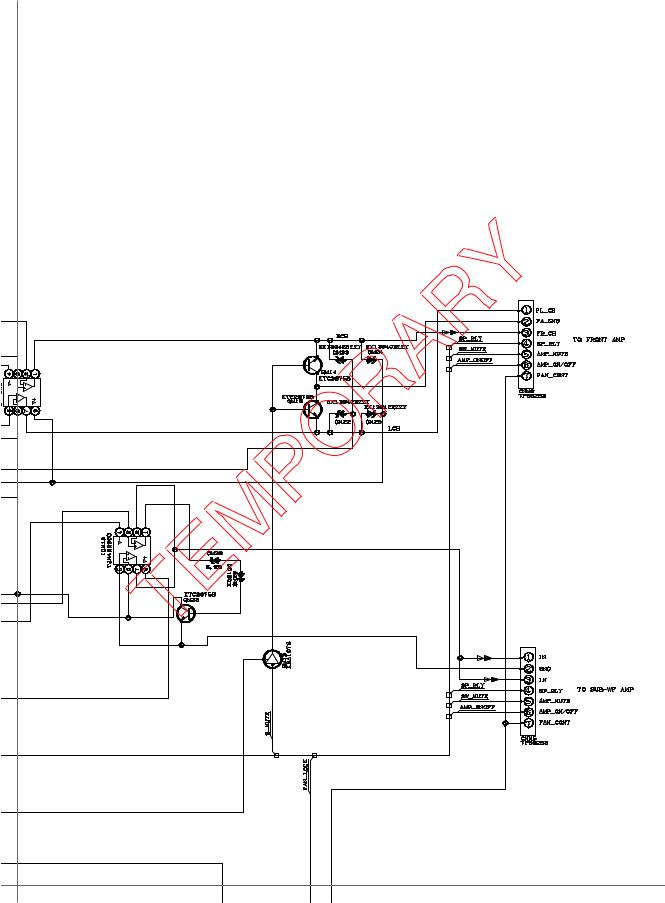
Figure 4-4: BLOCK DIAGRAM (4/8)
4 – 4
AN-GR500H
Figure 4-5: BLOCK DIAGRAM (5/8)
4 – 5
![]()
AN-GR500H
ICM7
IXA225AW
M3030RFGPFP
Figure 4-6: BLOCK DIAGRAM (6/8)
4 – 6
|
AN-GR500H |
|
Figure 4-7: BLOCK DIAGRAM (7/8) |
4 – 7
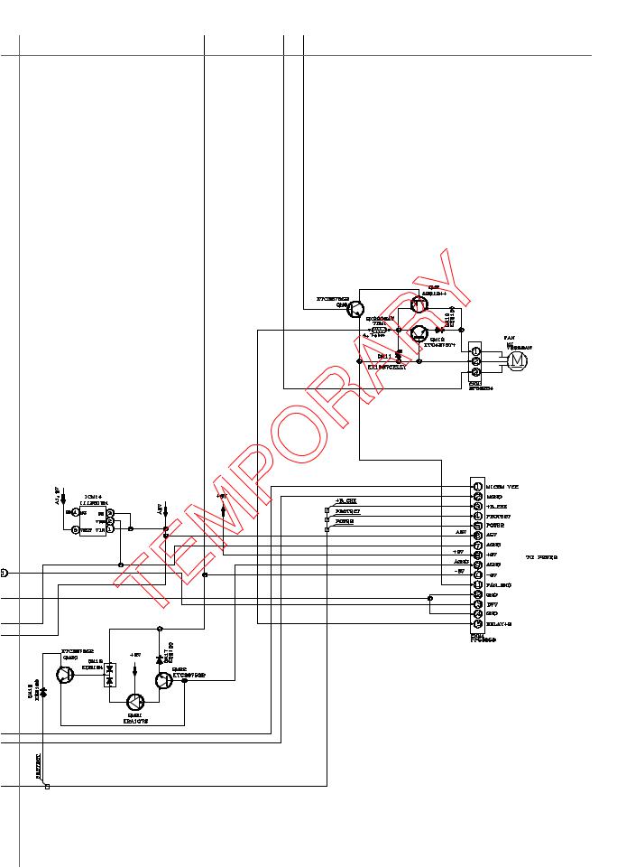
AN-GR500H
Figure 4-8: BLOCK DIAGRAM (8/8)
4 – 8
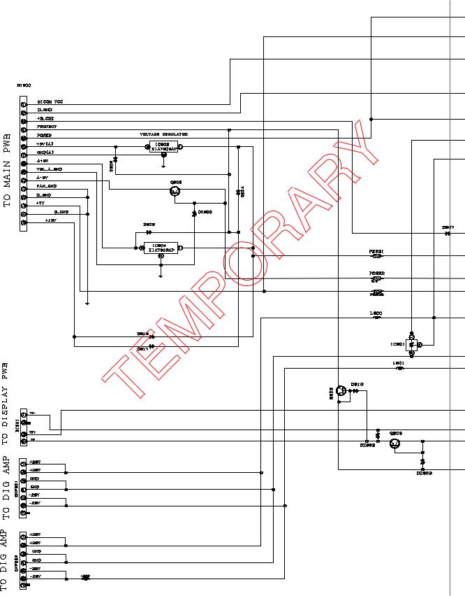
AN-GR500H
[2] Power Block Diagrams
Figure 4-9: POWER BLOCK DIAGRAM (1/2)
4 – 9

AN-GR500H
AC POWER SUPPLY
Figure 4-10: POWER BLOCK DIAGRAM (2/2)
4 – 10
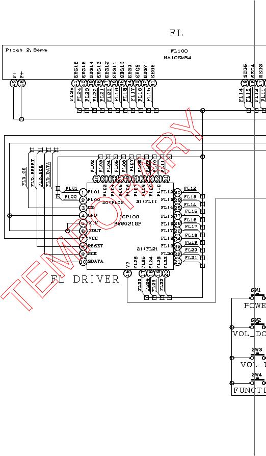
AN-GR500H
[3] Display Block Diagrams
Figure 4-11: DISPLAY BLOCK DIAGRAM (1/2)
4 – 11
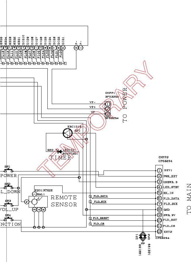
AN-GR500H
Figure 4-12: DISPLAY BLOCK DIAGRAM (2/2)
4 – 12
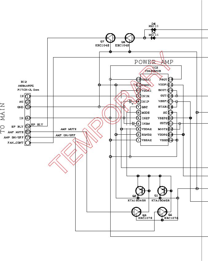
AN-GR500H
[4] Amplifier Block Diagram
0.1/50V C50
C20
0.1/50V
8
Figure 4-13: AMPLIFIER BLOCK DIAGRAM (1/2)
4 – 13
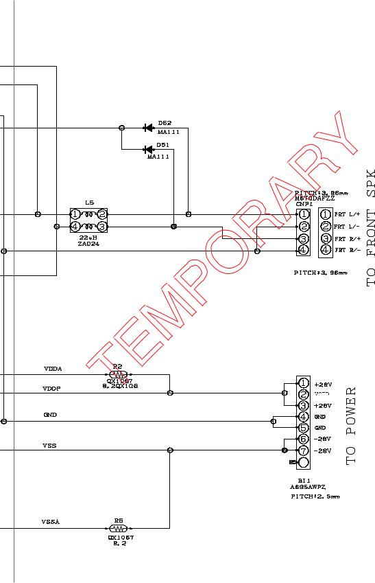
AN-GR500H
8
Figure 4-14: AMPLIFIER BLOCK DIAGRAM (2/2)
4 – 14
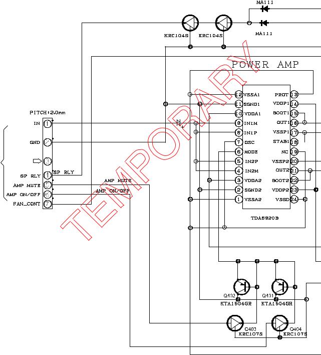
AN-GR500H
[5] Subwoofer Block Diagram
TO MAIN SECTION
|
D406 |
||
|
Q407 |
Q406 |
D404 |
|
Bi402 |
||
|
A696AWPZ |
||
|
C418 |
||
|
4.7/50V |
||
|
NC |
||
|
IC402 |
Figure 4-15: SUBWOOFER BLOCK DIAGRAM (1/2)
4 – 15
![]()
AN-GR500H
|
D451 |
QCNCMA045AW02 |
||||||||
|
L405 |
CNP401 |
TO |
SUBWOOFER |
||||||
|
C442 |
0.015/ |
||||||||
|
C439 |
0.015/ |
50V |
50V |
||||||
|
R402 |
|||||||||
|
NC |
SECTION |
||||||||
|
TO |
|||||||||
|
NC |
MAIN |
||||||||
|
Bi403 |
|||||||||
|
A2393AWZZ |
|||||||||
|
R405 |
Figure 4-16: SUBWOOFER BLOCK DIAGRAM (2/2)
4 – 16

AN-GR500H
CHAPTER5. 5. CIRCUIT DESCRIPTION
[1]WAVEFORMS OF CD CIRCUIT
[1]To Check And Cancel Protect Circuit Detection Line
1.After the power is turned on, the microprocessor (ICM7) built in this model continuously monitors the following defective operation. If any abnormality occurs, all power is shut down except in the microprocessor drive circuit.
1)An abnormal drop of each regulator output voltage.
(The protection circuit operates when the regulator output voltage is below 1.5 V.) The power is shut down immediately with no display.
2)Defect of the cooling fan motor and the cooling fan drive circuit. (Stoppage, etc.) The power is turned off after “FAN LOCK” is displayed.
3)Over voltage or reduced voltage of power supply.
The power is shut down immediately with no display when voltage is abnormal.
2.Failure detection conditions of the built-in microprocessor, check of the detection line and solution.
Conditions
1)To detect failure according to voltage of the microprocessor ICM7 pin 91.
2)Abnormal if pulse signals are not input into the pin 5 (FAN LOCK) for more than 5 seconds.
3)Abnormal if the voltage of the pin 97 (+B CHECK) is lower than 1.2 V or higher than 3.0 V.
1.Check of the detection line and solution
NOTE: If the microprocessor detects failures of 1), 2) and 3) above, it does not operate protectively when its PROTECT, and +B CHECK detection lines are disconnected.
When these failures are caused by output short-circuit of each regulator, components and PWB of the regulator may burn out. If the cause is not clear, do not disconnect the detection line.
(Even if any failure is detected, conduction is available for 0.5 second. You can check conduction by an oscilloscope, etc. However, a tester is not available due to rapid rise and decay of voltage.)
1. When output voltage of each regulator drops abnormally.
Connect the oscilloscope to the regulated output of the regulator and power on the system. If the voltage is significantly lower than that shown in the circuit diagram (approx. 1.5 V or less), the regulator itself and the destination circuit are suspected.
5 – 1

AN-GR500H
[2] Failure Detection Identification Using STANDBY LED
1. Identification format using STANDBY LED
If any failure is detected, STANDBY LED blinks red after power off (see Fig. 1 below). You can identify the failure state by checking which LED output number from the frame head is blinking 4 times each for 2 seconds.
Fig. 1 shows the LED output No. 2. is blinking due to failure.
|
Power OFF |
||||||||||||||
|
1 frame |
||||||||||||||
|
3sec |
3sec |
3sec |
||||||||||||
|
2sec |
2sec |
2sec |
||||||||||||
|
LED output |
No.1 |
No.2 |
No.3 |
|||||||||||
Normally, LED light up for 2 seconds and light off for 1 second on a 3-second cycle (6 times from No. 1 to No. 6). For No.7, LED light off for 3 seconds, showing the frame end (for recognition of the frame head).
In No. 2, LED blinks alternately at shorter intervals than usual for failure identification. For failure status, refer to the appendix, “STAND-BY LED Error Message”.
3sec 3sec
2sec
|
No.6 |
No.7 |
No.1 |
|||
Alternate blinking for failure detection
|
3sec |
As shown in Fig. 1, LED alternately blinks due to failure on a |
|||
|
Red ON |
500-msec cycle with duty of 50%. |
|||
|
2sec |
||||
|
500m |
500m |
500m |
500m |
|
|
LED output |
Figure 1
2. Failure detection
1.SYS-PROTECT detection: To detect failure of the power supply circuit (except the 1.8 V power supply circuit).
2.B_CHECK detection: To check timing at power ON/OFF and detect over voltage and reduced voltage of the primary AC power after the power is turned on.
3.AVCK detection: To detect failure of the 1.8 V power supply circuit (AVCK1 and AVCK2).
4.AMP_SW_PROT detection: To detect failure in the subwoofer AMP.
3. STANDBY LED Error Message
|
No. |
Name of failure detection |
Solution |
|
1 |
SYS-PROTECT detection |
Immediate power shut-down; Identification No.1 blinking |
|
2 |
B_CHECK detection |
Immediate power shut-down; Identification No.2 blinking in case of over voltage |
|
No blinking in case of reduced voltage |
||
|
3 |
AVCK detection |
Immediate power shut-down; Identification No.3 blinking |
|
4 |
AMP_SW_PROT detection |
Immediate power shut-down; Identification No.6 blinking |
5 – 2

AN-GR500H
[3] Waveforms Of SUBWOOFER Circuit
(at no signal)
2006/07/03
16
21
5 – 3

5 – 4

AN-GR500H
|
ICM10 |
ICM3 |
||||||||||||||
|
PIN NO. |
VOLTAGE (V) |
PIN NO. |
VOLTAGE (V) |
PIN NO. |
VOLTAGE (V) |
PIN NO. |
VOLTAGE (V) |
||||||||
|
1 |
1.63 |
41 |
0.00 |
1 |
0.67 |
15 |
0.00 |
||||||||
|
2 |
0.00 |
42 |
0.00 |
2 |
0.54 |
16 |
2.58 |
||||||||
|
3 |
1.63 |
43 |
0.00 |
3 |
1.51 |
17 |
2.53 |
||||||||
|
4 |
0.00 |
44 |
3.13 |
4 |
1.51 |
18 |
0.00 |
||||||||
|
5 |
1.67 |
45 |
0.00 |
5 |
1.51 |
19 |
3.20 |
||||||||
|
6 |
0.00 |
46 |
3.13 |
6 |
3.11 |
20 |
0.00 |
||||||||
|
7 |
0.00 |
47 |
1.52 |
7 |
0.00 |
21 |
3.14 |
||||||||
|
8 |
0.00 |
48 |
1.52 |
8 |
0.00 |
22 |
0.00 |
||||||||
|
9 |
0.00 |
49 |
0.00 |
9 |
3.12 |
23 |
3.22 |
||||||||
|
10 |
1.66 |
50 |
1.62 |
10 |
0.90 |
24 |
1.62 |
||||||||
|
11 |
0.00 |
51 |
0.00 |
11 |
0.60 |
25 |
1.60 |
||||||||
|
12 |
1.48 |
52 |
1.65 |
12 |
0.70 |
26 |
0.00 |
||||||||
|
13 |
1.49 |
53 |
0.00 |
13 |
0.70 |
27 |
1.53 |
||||||||
|
14 |
3.14 |
54 |
0.00 |
14 |
0.00 |
28 |
1.59 |
||||||||
|
15 |
0.00 |
55 |
0.00 |
||||||||||||
|
16 |
0.00 |
56 |
0.00 |
ICP100 |
|||||||||||
|
17 |
0.00 |
57 |
0.00 |
PIN NO. |
VOLTAGE (V) |
PIN NO. |
VOLTAGE (V) |
||||||||
|
1 |
-31.28 |
21 |
-34.12 |
||||||||||||
|
18 |
0.00 |
58 |
0.00 |
||||||||||||
|
2 |
-31.29 |
22 |
-34.37 |
||||||||||||
|
19 |
0.00 |
59 |
0.00 |
||||||||||||
|
3 |
1.98 |
23 |
-34.36 |
||||||||||||
|
20 |
0.00 |
60 |
0.00 |
||||||||||||
|
4 |
0.00 |
24 |
-34.46 |
||||||||||||
|
21 |
0.00 |
61 |
3.12 |
||||||||||||
|
5 |
1.46 |
25 |
0.00 |
||||||||||||
|
22 |
3.10 |
62 |
3.12 |
||||||||||||
|
6 |
1.45 |
26 |
0.00 |
||||||||||||
|
23 |
0.00 |
63 |
0.00 |
||||||||||||
|
7 |
3.32 |
27 |
-34.37 |
||||||||||||
|
24 |
4.72 |
64 |
0.00 |
||||||||||||
|
8 |
3.31 |
28 |
-34.35 |
||||||||||||
|
25 |
4.72 |
65 |
1.65 |
||||||||||||
|
9 |
3.26 |
29 |
-34.36 |
||||||||||||
|
26 |
0.00 |
66 |
3.11 |
||||||||||||
|
10 |
0.12 |
30 |
-33.73 |
||||||||||||
|
27 |
2.29 |
67 |
3.11 |
||||||||||||
|
11 |
-34.45 |
31 |
-34.76 |
||||||||||||
|
28 |
2.29 |
68 |
3.12 |
||||||||||||
|
12 |
-34.22 |
32 |
-34.36 |
||||||||||||
|
29 |
2.24 |
69 |
3.13 |
||||||||||||
|
13 |
-34.43 |
33 |
-34.35 |
||||||||||||
|
30 |
2.25 |
70 |
3.12 |
||||||||||||
|
14 |
-34.41 |
34 |
-34.34 |
||||||||||||
|
31 |
2.29 |
71 |
2.62 |
||||||||||||
|
15 |
-34.65 |
35 |
-34.34 |
||||||||||||
|
32 |
2.30 |
72 |
0.00 |
||||||||||||
|
16 |
-34.42 |
36 |
-31.35 |
||||||||||||
|
33 |
0.00 |
73 |
2.62 |
||||||||||||
|
17 |
-34.46 |
37 |
-34.36 |
||||||||||||
|
34 |
4.72 |
74 |
0.00 |
||||||||||||
|
18 |
0.00 |
38 |
-31.56 |
||||||||||||
|
35 |
2.30 |
75 |
1.65 |
||||||||||||
|
19 |
-34.46 |
39 |
-34.34 |
||||||||||||
|
36 |
2.91 |
76 |
0.00 |
||||||||||||
|
20 |
0.00 |
40 |
-34.32 |
||||||||||||
|
37 |
0.00 |
77 |
0.00 |
||||||||||||
|
38 |
0.00 |
78 |
3.12 |
||||||||||||
|
ICT1 |
|||||||||||||||
|
39 |
0.00 |
79 |
0.00 |
||||||||||||
|
PIN NO. |
VOLTAGE (V) |
||||||||||||||
|
40 |
4.73 |
80 |
3.12 |
||||||||||||
|
1 |
2.30 |
||||||||||||||
|
2 |
2.33 |
||||||||||||||
|
Q1 |
ICM14 |
3 |
4.80 |
||||||||||||
|
PIN NO. |
VOLTAGE (V) |
PIN NO. |
VOLTAGE (V) |
4 |
0.00 |
||||||||||
|
C |
0.00 |
1 |
4.79 |
5 |
2.36 |
||||||||||
|
B |
6.03 |
2 |
0.00 |
6 |
2.29 |
||||||||||
|
E |
5.66 |
3 |
4.73 |
7 |
0.00 |
||||||||||
|
4 |
0.00 |
8 |
2.43 |
||||||||||||
|
5 |
1.63 |
9 |
2.22 |
||||||||||||
|
Q2 |
10 |
0.00 |
|||||||||||||
|
PIN NO. |
VOLTAGE (V) |
11 |
4.74 |
||||||||||||
|
C |
0.00 |
ICM17 |
12 |
4.75 |
|||||||||||
|
B |
4.73 |
PIN NO. |
VOLTAGE (V) |
13 |
4.74 |
||||||||||
|
E |
5.25 |
1 |
4.73 |
14 |
0.00 |
||||||||||
|
2 |
0.00 |
15 |
4.84 |
||||||||||||
|
3 |
4.74 |
16 |
3.22 |
||||||||||||
|
Q3 |
4 |
0.00 |
|||||||||||||
|
PIN NO. |
VOLTAGE (V) |
5 |
3.10 |
||||||||||||
|
C |
4.67 |
ICM8 |
|||||||||||||
|
B |
0.00 |
||||||||||||||
|
PIN NO. |
VOLTAGE (V) |
||||||||||||||
|
E |
0.00 |
||||||||||||||
|
ICM9 |
1 |
0.00 |
|||||||||||||
|
PIN NO. |
VOLTAGE (V) |
2 |
0.00 |
||||||||||||
|
1 |
3.01 |
3 |
0.00 |
||||||||||||
|
Q4 |
2 |
3.01 |
4 |
0.00 |
|||||||||||
|
PIN NO. |
VOLTAGE (V) |
3 |
0.00 |
5 |
3.17 |
||||||||||
|
C |
5.64 |
6 |
3.15 |
||||||||||||
|
4 |
0.00 |
||||||||||||||
|
B |
0.00 |
||||||||||||||
|
5 |
0.00 |
7 |
3.16 |
||||||||||||
|
E |
0.00 |
||||||||||||||
|
8 |
3.13 |
5 – 5

|
ICM5 |
ICA1 |
IC2 |
||||||
|
PIN NO. |
VOLTAGE (V) |
PIN NO. |
VOLTAGE (V) |
PIN NO. |
VOLTAGE (V) |
|||
|
1 |
0.00 |
1 |
0.00 |
1 |
-25.77 |
|||
|
2 |
0.00 |
2 |
1.52 |
2 |
0.00 |
|||
|
3 |
0.00 |
3 |
1.65 |
3 |
25.89 |
|||
|
4 |
-8.94 |
4 |
1.02 |
4 |
0.00 |
|||
|
5 |
0.00 |
5 |
1.58 |
5 |
0.00 |
|||
|
6 |
0.00 |
6 |
0.00 |
6 |
5.23 |
|||
|
7 |
0.00 |
7 |
3.12 |
7 |
-22.91 |
|||
|
8 |
8.73 |
8 |
0.00 |
8 |
0.00 |
|||
|
9 |
0.00 |
9 |
0.00 |
|||||
|
10 |
2.61 |
10 |
25.86 |
|||||
|
ICM12 |
11 |
2.61 |
11 |
0.00 |
||||
|
PIN NO. |
VOLTAGE (V) |
12 |
0.00 |
12 |
-25.76 |
|||
|
1 |
0.00 |
13 |
2.28 |
13 |
-17.84 |
|||
|
2 |
0.00 |
14 |
0.00 |
14 |
26.14 |
|||
|
3 |
0.00 |
15 |
0.00 |
15 |
10.36 |
|||
|
4 |
-8.93 |
16 |
4.73 |
16 |
-0.11 |
|||
|
17 |
0.00 |
17 |
-25.95 |
|||||
|
5 |
0.00 |
|||||||
|
18 |
1.09 |
18 |
-13.81 |
|||||
|
6 |
0.00 |
|||||||
|
19 |
1.05 |
19 |
-25.76 |
|||||
|
7 |
0.00 |
|||||||
|
20 |
1.09 |
20 |
-25.96 |
|||||
|
8 |
8.60 |
|||||||
|
21 |
1.14 |
21 |
-0.13 |
|||||
|
22 |
0.84 |
22 |
10.38 |
|||||
|
ICM11 |
23 |
0.84 |
23 |
26.14 |
||||
|
24 |
0.83 |
24 |
-25.77 |
|||||
|
PIN NO. |
VOLTAGE (V) |
|||||||
|
25 |
0.82 |
|||||||
|
1 |
4.89 |
|||||||
|
26 |
0.82 |
|||||||
|
2 |
0.00 |
|||||||
|
27 |
0.80 |
|||||||
|
3 |
4.90 |
|||||||
|
28 |
0.80 |
|||||||
|
4 |
0.00 |
|||||||
50.00
60.00
|
7 |
0.00 |
ICM15 |
||
|
PIN NO. VOLTAGE (V) |
||||
|
8 |
0.00 |
|||
|
9 |
0.00 |
1 |
9.16 |
|
|
10 |
8.59 |
2 |
0.00 |
|
|
11 |
4.90 |
3 |
3.12 |
124.80
130.00
|
14 |
4.91 |
ICM16 |
||
|
PIN NO. |
VOLTAGE (V) |
|||
|
1 |
0.00 |
|||
|
ICM18 |
2 |
3.12 |
||
|
PIN NO. VOLTAGE (V) |
3 |
1.64 |
||
|
1 |
0.00 |
4 |
2.22 |
|
|
5 |
0.00 |
|||
|
2 |
0.95 |
|||
33.12
40.00
|
5 |
0.00 |
QM19 |
|||||
|
6 |
0.00 |
PIN NO. |
VOLTAGE (V) |
||||
|
C |
1.66 |
||||||
|
7 |
0.00 |
||||||
|
B |
2.49 |
||||||
|
8 |
3.12 |
||||||
|
E |
3.15 |
||||||
|
Q6 |
|||||||
|
PIN NO. |
VOLTAGE (V) |
||||||
|
C |
0.00 |
||||||
|
B |
30.53 |
||||||
|
E |
0.00 |
||||||
|
PIN NO. |
Q7 |
||||||
|
VOLTAGE (V) |
|||||||
|
C |
3.33 |
||||||
|
B |
0.00 |
||||||
|
E |
0.00 |
AN-GR500H
IC800
PIN NO. VOLTAGE (V)
10.40
21.11
32.05
40.00
50.96
610.39
71.69
80.29
IC801
PIN NO. VOLTAGE (V)
116.68
20.00
32.46
IC802
PIN NO. VOLTAGE (V)
13.87
20.00
38.08
IC803
PIN NO. VOLTAGE (V)
114.61
20.00
34.97
IC804
PIN NO. VOLTAGE (V)
114.61
20.00
39.00
|
Q802 |
||||
|
PIN NO. |
VOLTAGE (V) |
|||
|
C |
0.00 |
|||
|
B |
0.68 |
|||
|
E |
0.00 |
|||
|
Q803 |
||||
|
PIN NO. |
VOLTAGE (V) |
|||
|
C |
0.00 |
|||
|
B |
9.82 |
|||
|
E |
-9.21 |
|||
|
Q804 |
||||
|
PIN NO. |
VOLTAGE (V) |
|||
|
D |
389.54 |
|||
|
G |
0.62 |
|||
|
S |
0.00 |
|||
|
QP1 |
||||
|
PIN NO. |
VOLTAGE (V) |
|||
|
C |
2.95 |
|||
|
B |
0.00 |
|||
|
E |
0.00 |
5 – 6

AN-GR500H
|
IC402 |
Q401 |
Q402 |
|||||
|
PIN NO. VOLTAGE (V) |
PIN NO. |
VOLTAGE (V) |
PIN NO. |
VOLTAGE (V) |
|||
|
1 |
-25.90 |
C |
0.00 |
C |
0.00 |
||
|
2 |
0.00 |
B |
5.20 |
B |
4.70 |
||
|
3 |
26.00 |
E |
5.60 |
E |
5.20 |
40.00
50.00
|
6 |
5.20 |
Q403 |
Q404 |
||||
|
7 |
-22.50 |
PIN NO. |
VOLTAGE (V) |
PIN NO. |
VOLTAGE (V) |
||
|
8 |
0.00 |
C |
4.70 |
C |
5.10 |
||
|
9 |
0.00 |
B |
0.00 |
B |
0.00 |
||
|
10 |
26.00 |
E |
0.00 |
E |
0.00 |
110.00
12-25.90
|
13 |
-17.80 |
Q406 |
Q407 |
||||
|
14 |
26.30 |
PIN NO. |
VOLTAGE (V) |
PIN NO. |
VOLTAGE (V) |
||
|
15 |
10.70 |
C |
0.00 |
C |
3.10 |
||
|
16 |
-0.10 |
B |
8.60 |
B |
0.00 |
||
|
17 |
-26.10 |
E |
0.00 |
E |
0.00 |
||
18-13.60
19-25.90
20-26.10
21-0.10
2210.80
2326.20
24-25.90
5 – 7

AN-GR500H
CHAPTER 6. CIRCUIT SCHEMATICS AND PARTS LAYOUT
[1] Notes On Schematic Diagram
•Resistor:
To differentiate the units of resistors, such symbol as K and M are used: the symbol K means 1000 ohm and the symbol M means 1000 kohm and the resistor without any symbol is ohm-type resistor. Besides, the one with “Fusible” is a fuse type.
•Capacitor:
To indicate the unit of capacitor, a symbol P is used: this symbol P means pico-farad and the unit of the capacitor without such a symbol is microfarad. As to electrolytic capacitor, the expression “capacitance/ withstand voltage” is used.
(CH), (TH), (RH), (UJ): Temperature compensation (ML): Mylar type
(P.P.): Polypropylene type
•Schematic diagram and Wiring Side of P.W.Board for this model are subject to change for improvement without prior notice.
•The indicated voltage in each section is the one measured by Digital Multimeter between such a section and the chassis with no signal given.
1.In the tuner section, indicates FM stereo
|
• Parts marked with “ “ ( |
) are |
|||||||||
important for maintaining the safety of the set. Be sure to replace these parts with specified ones for maintaining the safety and performance of the set.
|
REF. NO |
DESCRIPTION |
POSITION |
|||||
|
SW1 |
ON/STAND-BY |
ON-OFF |
|||||
|
SW2 |
VOLUME DOWN |
ON-OFF |
|||||
|
SW3 |
VOLUME UP |
ON-OFF |
|||||
|
SW4 |
FUNCTION |
ON-OFF |
|||||
|
[2] Types Of Transistor And LED |
|||||||
|
TOP VIEW |
TOP VIEW |
||||||
|
FRONT |
B |
||||||
|
(3) |
|||||||
|
FRONT |
VIEW |
||||||
|
TOP |
C |
||||||
|
VIEW |
VIEW |
(2) |
|||||
|
E |
|||||||
|
(1) |
|||||||
|
B C E |
E C B |
||||||
|
2SA2012 |
KRC107S |
1N404S |
|||||
|
1 2 |
3 |
(S)(G)(D) |
D1SS119 |
||||
|
KTC4375Y |
(1)(2)(3) |
KRC101S |
1N4148H |
||||
|
SARS03 |
KTA1266 GR |
KRA107S |
DRL204F |
||||
|
1. Anode |
KTA1023Y |
KRC104S |
1N4004 |
||||
|
2. No Contact |
KTC3199 GR |
KTC3875 GR |
KDS160 |
||||
|
3. Cathode |
PST3229N |
KTA1504 GR |
MA111 |
||||
|
KTC2875B |
|||||||
|
6206P39T |
|||||||
|
TOP VIEW |
|||||||
|
FRONT |
FRONT |
||||||
|
VIEW |
|||||||
|
VIEW |
|||||||
|
Green |
Red |
||||||
|
AC AC |
Cathode |
Cathode |
|||||
|
B C E |
KDS226 |
TS10B05G |
Anode |
||||
|
KTA1046Y |
TS20P05G |
||||||
|
STH102CF |
KDS184 |
TS6P05G |
A309SGM2E7 |
||||
6 – 1

AN-GR500H
[3] Schematic Diagram
|
MAIN PWB-A1 |
|
AUDIO SIGNAL |
|
DM31 |
|
KDS226 |
|
CM107(0.1) |
|
LUGM2 |
Figure 6-1: MAIN SCHEMATIC DIAGRAM (1/8)
6 – 2
![]()
AN-GR500H
Figure 6-2: MAIN SCHEMATIC DIAGRAM (2/8)
6 – 3

Figure 6-3: MAIN SCHEMATIC DIAGRAM (3/8)
6 – 4

AN-GR500H
FRONT AMP
TO
SUBWOOFER AMP
TO
Figure 6-4: MAIN SCHEMATIC DIAGRAM (4/8)
6 – 5

|
AN-GR500H |
||
|
TO TUNER PACK |
||
|
CM282 |
CM280 |
(100P) |
|
100pF |
||
|
PWBINTERFACE |
||
|
TO |
CM283 (100P) |
|
|
CM281 (100P) |
Figure 6-5: MAIN SCHEMATIC DIAGRAM (5/8)
6 – 6

|
AN-GR500H |
|
FOR REFLASH ONLY |
Figure 6-6: MAIN SCHEMATIC DIAGRAM (6/8)
6 – 7
 Loading…