
Faults / Alarms
Fault
No.
Cause as a function of fault value
(r047.001, r949.001 or r949.009 with acknowledged error)
F080
Error in initialization of a CB/TB board
Possible causes for fault values 1 and 6:
•
CB/TB board is defective
•
CB/TB board is not installed correctly
•
CB/TB board is taking too long to run up (e.g. due to very complex TB configuration)
Fault value (r949 index 001):
1
The «Heartbeat counter» of the CB/TB has not started to
count within 20 s
2
The product version of the installed CT/TB board is not
compatible with the SIMOREG 6RA70 converter
5
Parameters P918, U711 to U721 are not correctly set or
not accepted after a change by means of U710 = 0
setting. (The meanings of these parameters are defined
in the manual for the relevant CB board, see also
function diagrams, Section 8, Sheets 30 and 31)
6
The initialization run for a CB/TB board has not been
completed within 40 s
F081
CB/TB heartbeat error
CB/TB has not incremented the monitoring counter for a period
of 800 ms
Possible causes of fault
•
CB/TB board is defective
•
CB/TB board is not correctly installed
F082
CB/TB message timeout or error in data exchange
Possible causes of fault
•
CB/TB PZD message timeout (with fault value 10)
•
Excessive EMC-related interference
(e.g. due to unprotected contactors, unscreened cables, loose screen connections)
•
CB/TB board is defective
•
CB/TB board is not correctly inserted
Fault value (r949 index 001):
1
Fault in alarm channel from CB to basic unit
2
Fault in alarm channel from TB to basic unit
3
Fault in fault channel from TB to basic unit
5
Fault in parameter job channel from CB to basic unit
6
Fault in parameter response channel from basic unit to
CB
7
Fault in parameter job channel from TB to basic unit
8
Fault in parameter response channel from basic unit to
TB
10
CB/TB process data failure (message timeout period set
in U722)
11
Fault in parameter job channel from PMU to TB
12
Fault in parameter response channel from TB to PMU
10-22
Description
Further information (r047.002 to r047.016)
r047 index 002 to 016:
i015 Code number of board:
st
1
TB or 1
nd
2
2
CB
i002 Code number of slot containing incompatible board:
2
Slot D
3
Slot E
4
Slot F
5
Slot G
6
CB when configuration includes TB
i015 Code number of board:
st
1
TB or 1
nd
2
2
CB
i015 Code number of board:
st
1
TB or 1
nd
2
2
CB
i015 Code number of board:
st
1
TB or 1
nd
2
2
CB
r047 Index 002 to 016:
i015 Code number of board:
st
1
TB or 1
nd
2
2
CB
i015 Code number of board:
st
1
TB or 1
nd
2
2
CB
i015 Code number of board:
st
1
1
TB or 1
nd
2
2
CB
i015 Code number of board:
st
1
TB or 1
nd
2
2
CB
SIMOREG DC Master
CB
CB
CB
CB
CB
CB
st
CB
CB
SIEMENS AG
6RX1700-0AD76
Operating Instructions
02.00
F030 fault in DC drive Simoreg 6RA70:dc master
Problem:
During running condition DC motor tripped showing “F030” fault.
Description:
I work in a Steel mill. And it is one of the renowned Steel mills in my country. Previously it was 18 stand mills but after some correction it is now 20 stand mill and for this purpose we changed one of DC motor named shear#2 or flying shear. We replaced it with 250KW DC motor. Previously it was 170KW. After changing this we faced with this new problem. It some times tripped in running condition especially in 3X12mm rolling showing F030 fault. We used DC drives from siemens and the model was Simoreg 6RA70.
The fault code was 2.
Analysis:
From simoreg DC master 6RA70 manual we see F30 means the followings
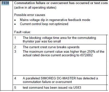
From fault code we see the root cause of this fault trigger is “The current crest curve breaks upwards” as our fault code is 2 (two).
Now the interesting part, from this we understand that this problem must related to some monitoring function. As Shear#2 does not run all the time and only used for cobble chopping and optimization chopping, it is probable that it may take some extra current for very short time.
Then we found the particular monitoring parameter. It is U580 (2580) “Control word for commutation monitoring”.

By this parameter we define which commutation monitoring criteria the drive will use. In our drive it was select in 4. So Decision criterion 3 that means maximum current actual value is evaluated. That’s the reason as it was reaching the limit as it tripped.
Then we changed the parameter from 4 to 7 means all three criterion will be used.
Then the problem solved.
Regarding the manual and figure: 2
Each decision criterion has a numeric code.
If more than one decision criterion is to be evaluated, the sum of the relevant digits must be entered.
There also rules for selecting the parameter. If u select 0 then “none of the three criteria are evaluated” will be selected. If u select 1 then “Decision criterion 1 (sufficient voltage time area for commutation) is evaluated” will be selected. If u select 2 then “Decision criterion 2 (curvature of the current crest curve) is evaluated” will be selected. If u select 4 then “Decision criterion 3 (maximum current actual value) is evaluated” will be selected.
Now if you want to select both criterions 1 & 2 then enter value 3. If you want to select both criterions 2 & 4 then select 6. If you want to select all of the criterions then select 7, the sum of all codes.
Саму программу на симореге для меня составить не проблема, а вот профибас темный лес)
Для этого контроллера управляющая программа составлена в экселе, лично у меня не хватает ума в ней разобраться)
Сам принцип работы сети такой:
контроллер 1 (масте1) — привод1 (насос1) — привод2 (насос2) — привод3 …. привод6(ФКУ) — контроллер2 (мастер2)
Контролер 2 является ведущим класса 1, имеет сетевой адрес С.А.=2, и осуществляет связь с цифровыми модулями управления тиристорными преобразователями 3 — 5,
Контроллер 1 также является ведущим класса 1, имеет сетевой адрес С.А.=1 и осуществляет связь с ТП насосов 1 — 2,
Кроме обмена данными с ведомыми устройствами, контроллеры 1 и 2 два раза за цикл обмениваются данными между собой.
Обмен данными происходит в следующем порядке:
— ведущий контроллер 1 обменивается данными со своими ведомыми устройствами в порядке возрастания сетевого адреса, т.е. сначала обменивается данными с насосом 1, затем насос2.
— после обмена данными с ведомыми контроллер 1 обменивается данными с ведущим контроллером 2 и передает ему управление сетью;
— ведущий контроллер 2 обменивается данными со своими ведомыми устройствами в порядке возрастания сетевого адреса,
— после обмена данными с ведомыми, контроллер 2 обменивается данными с ведущим контроллером1, и передает ему управление сетью;
— далее цикл обмена данными повторяется.
т.е. привод ФКУ в этом обмене не учавствует, но данные с насосов передаются для фку (К115), по всей видимости в контроллер 1.
Чуть позже скину ссылку на проект контроллера в экселе, если кому будет интересно взглянуть