
1 Alarms
No. 109
Explanation
Not allowed if
Remedy
No. 115
Explanation
Not allowed if
Remedy
No. 116
Explanation
Not allowed if
Remedy
No. 117
Explanation
Not allowed if
Remedy
No. 118
Explanation
Not allowed if
Remedy
1.4
Error code
Error text
Extension 1
Extension 2
Explanation
Remedy
Error code
Error text
Extension 1
1-678
Deactivate: Axis is now controlled by the PLC (VDI signal).
The axis is not controlled by the PLC. Not for all axis types at present.
—
The event is triggered by the positive PLC edge of the signal «Repos-Mode-Edge».
The channel is active (program running, block search, loading machine data).
> Abort the program with the Reset key or stop the program (not with block search, load-
ing machine data).
Activate tool-management commands (Ch. VDI signal).
The NCK channel is in a state other than «ready».
> Abort the program or process with the Reset key or wait for end of program.
Deactivate tool-management commands (Ch. VDI signal).
The NCK channel is in a state other than «ready».
> Abort the program or process with the Reset key or wait for end of program.
Selection of desired safety limitations (SGE) (always allowed).
—
—
After the error codes 1 listed below, an error code 2 may be specified. This must be inter-
preted as the hexadecimal number of the terminal block/module.
0001H
Error in P:-RAM
—
Incorrect address
When the program memory was being tested during power-up, it was detected that the
written bitmap could not be read back.
Cause: Hardware error on control module.
Error only occurs with drive software V1.x (EPROM version). The error has been replaced
by system errors F034 and F035 in subsequent download versions.
Replace the control module.
0002H
Error in X: or Y:-RAM
—
Siemens AG, 2004. All rights reserved
SINUMERIK 840D/840Di/810D Diagnostics Guide (DA), 10.04 Edition
03.04

Новая система ЧПУ SINUMERIK 840D sl является модульной, открытой, гибкой, и унифицированной системой управления. Она предоставляет системную базу с функциями практически для любых технологий и станков.
Встроенная в приводную систему SINAMICS S120 и дополненная системой автоматизации SIMATIC S7-300 СЧПУ SINUMERIK 840D sl образует новую полностью цифровую систему, которая лучше всего подходит к использованию в среднем и высшем диапазоне рабочих характеристик.
Область применения
SINUMERIK 840D sl может использоваться для токарной, фрезерной обработки, сверления, шлифования, лазерной обработки, вырубки, штамповки, в производстве инструментов и форм, для задач высокоскоростного резания, для обработки дерева и стекла, для погрузочно-разгрузочных работ, на автоматических линиях и делительно-поворотных станках, в массовом и единичном производстве.
SINUMERIK 840DE sl существует в экспортном варианте для использования в странах, на вывоз в которые необходимо разрешение.
Характеристики
SINUMERIK 840D sl — это цифровая система ЧПУ для средних и сложных задач.
Максимальные рабочие характеристики и гибкость, особенно для сложных многоосевых систем.
Одинаковая открытость, начиная с эксплуатации и заканчивая ядром ЧПУ.
Интегральные сертифицированные функции безопасности для человека и станка: SINUMERIK Safety Integrated.
Проверенное операционное и программирующее ПО, такое как ShopMill или ShopTurn и продукты Motion Control Information System (MCIS) для производства.
Конструкция
SINUMERIK 840D sl объединяет ЧПУ, HMI, PLC, задачи регулирования по замкнутому циклу и коммуникации в одном SINUMERIK NCU (NCU 710.1/NCU 720.1/NCU 730.1). Программное обеспечение, необходимое для эксплуатации, программирования и визуализации, уже интегрировано в программное обеспечение NCU, поэтому оно выполняется на высокопроизводительном мультипроцессорном модуле NCU.
Для повышения рабочих характеристик можно использовать промышленный компьютер SINUMERIK PCU 50.3. На одном NCU/PCU можно использовать до 4 распределенных панелей оператора. Панель оператора может быть установлена как «тонкий клиент» на расстоянии до 100 м (328 футов).
Высокопроизводительный мультипроцессорный модуль NCU может быть установлен слева от сетевого модуля SINAMICS S120. При необходимости NCU может быть установлен отдельно на расстоянии до 100 м (328 футов). Для подключения используются кабели MOTION-CONNECT DRIVE-CLiQ от Siemens.
Функции
Возможность расширения аппаратного и программного обеспечения — как в ЧПУ, так и в области управления — обеспечивает исключительные условия для использования SINUMERIK 840D sl во многих областях. Начиная с простых задач позиционирования и заканчивая сложными многоосевыми системами. Мы предлагаем разные типы NCU для Ваших задач обработки.
С SINUMERIK 840D sl с NCU 710.1 доступно максимум 6 осей. На NCU 720.1 и NCU 730.1 количество осей и/или производительность СЧПУ может быть увеличена до 31 оси. NCU 730.1 рекомендуется использовать для максимальной динамики и точности в производстве форм или в области высокоскоростного резания. С помощью пакета фрезерной обработки можно просто и удобно решить такие задачи обработки, как фрезерование поверхностей произвольной формы.
Включены следующие функции:
Благодаря открытости HMI, ЧПУ и PLC пользователи могут применять свои специфичные профессиональные знания. SINUMERIK 840D sl обеспечивает открытость вплоть до ядра ЧПУ. Такая открытая архитектура и высокие вычислительные возможности системы SINUMERIK 840D sl означают, что функции СЧПУ могут быть гибко, быстро и недорого адаптированы к любой инновационной кинематике станков. Дополнительные функции, специфичные для конкретной технологии, могут быть позже загружены в качестве циклов компиляции.
С SINUMERIK 840D sl доступны интегрированные, сертифицированные функции безопасности SINUMERIK Safety Integrated. Постоянная и очень эффективная защита персонала и станков достигается простым, экономичным и практичным способом.
Источники:
https://sitek-group. com/by/destinations/premium-class/sinumerik-840d-sl/
Автор:
fart1234,
28 сентября 2017 в Sinumerik
-
Ответить в тему
-
Создать тему
-
Сейчас на странице
0 пользователей
Нет пользователей, просматривающих эту страницу.
-
Сообщения
-

-
-
-
Автор:
Fedor · Опубликовано: 27 минут назад
Жидкость обычно считают несжимаемой. То есть давление в ней не может меняться. Только сдвиги возможны. Вроде так …
-
Автор:
5axisCNC · Опубликовано: 35 минут назад
Если алю то лучше твердосплавные фрезы брать по нерже или жаропрочке.
Корпусные по алю скорость резания 800-1000 а монолит порядка 400; корпусятина с пластинами по цветнине тоже очень быстро выносит мясо
-
-
Автор:
Muwa · Опубликовано: 59 минут назад
Честно говоря не пользовался этой траекторией никогда, поэтому ХЗ почему такая логика. Может это «изюминка» новых версий КАМа))
-
Автор:
Дядя · Опубликовано: 1 час назад
Думаю это поможет )) , но почему изначально она получается над деталью ?
Я пробовал в старых версиях МС , траектория выводится нормально.
-
Автор:
Muwa · Опубликовано: 1 час назад
Я сдвинул геометрию по Z на 10мм вниз, траектория «криволинейная 2д» уползла следом за геометрией
-
Автор:
Anat2015 · Опубликовано: 1 час назад
Чем лучше вариант получать станки не напрямую из поднебесной, а через «батькиных сынов» — те хотя бы вот такие вещи, как неприкрученная ШВП, возможно мимо не пропустят. А при грамотном составлении договора будет с кого спросить. Но, это — деньги, пищевая цепочка длиннее.
-


Перейти к контенту
Значит,начну с Sander,мануалы на фирме SIEMENS выкладываются,чтобы заказчик примерно представлял,что и какую технику он может заказать.Как и в других областях,авторские права разработчиков этой техники строго охраняются.Существует специальная служба,которая регулярно шерстит «гугль»и мало не покажется,если произойдет утечка;-адвокаты там звери!
А теперь,по теме.Прежде чем выложить процедуру перезаписи NCK на SINUMERIK-810D,840D,хочу сразу предупредить,что переинсталляция NCK,шаг крайний и ответственный.Это крайняя мера и прибегать к ней нужно,если все остальные способы оказались неэффективны.
Добавлено 06-09-2009 19:52
Итак,если решились,то мы должны работать с ключом красного цвета,т.е. с первым уровнем доступа.Переведите его в предпоследнюю позицию.Дальше;
1.В окне «STARTAP»,введите ,удерживая кнопку «^» непрерывно ,код «S U N R I S E»
2.На SIMODRIVE-611,установить переключатель «S4» в положение «2»
Попробуйте сейчас прописать программы»PLC»,-это вариант «малой крови»,без вышибания информации ядра NCK
Если не пошло,тогда нет выбора и нужно инсталлировать NCK и PLC полностью.
Без наличия диска с программами NCK,PLC,SPF,MPF не начинайте инсталляцию!!!
Добавлено 06-09-2009 20:14
Теперь подробно,как выполняется процедура полного обнуления памяти.Все операции производятся на SIMODRIVE-611
1.S4—>»3″,выключить и включить машину
2.S4—>»4″,держать не более 3 секунд
3.S4—>»0″
4.S3—>»1″-обнуление регистров
5.S3—>»0″
6.S3—>»1″,выключaем и с задержкой 10 с. включaем машину.
7.S3—>»0″
Если, после обнуления,горят краcные лампочки «RF» и «RS»,то
8.S4—>»3″ с задержкой 3 с. неcколько раз повторить.
9.S4—>»0″-пишем параметры ядра NCK
10.S4—>»2″-пишем программы PLC
Добавлено 06-09-2009 20:25
Еcли обнуление и запись прошли без накладок,горят две зеленые лампочки.Теперь осталось:
1.Проверить наличие осей
2.Обязательно,перед «REFERENCE POINT» удалить код доступа и сменить красный ключ!
ВНИМАНИЕ! В процессе перезаписи возможно самопроизвольное изменение параметров интерфейса обмена данными,поэтому не надо паниковать,если запись не пошла с первого раза.Подкорректируйте параметры в окне «SERVICE».
Только что, David123 сказал:
Уважаемый @nein !
1) Насколько я понял, Вы умеете обращаться с архивами, первым делом сохраните текущий архив NC.
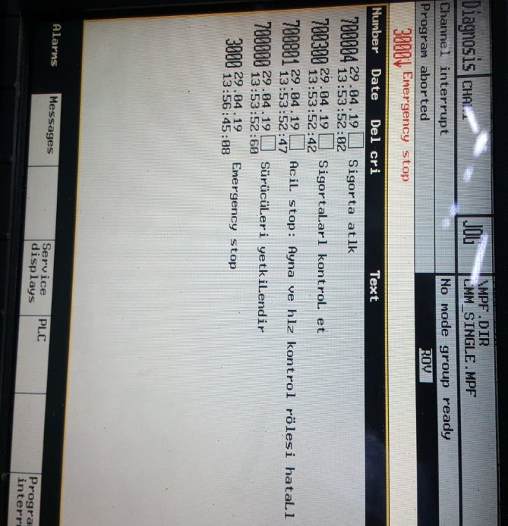
2) Ошибку 700004 — выдает электроавтоматика станка. Она должна быть описана в Руководстве по станку. Что там сказано?
3) Эта ошибка всегда выводится или ранее станок работал, выдавал готовую продукцию, но произошли какие-то обстоятельства, после чего происходит описываемое.
4) Эта ошибка выводится сразу после первоначальной загрузки системы или какие-то действия производятся на станке? Нет ли в строке вывода ошибки, сразу после номера 700004 символа «стрелка вниз». Это признак — одновременно появились несколько ошибок или сообщений. В области ДИАГНОСТИКА можно найти полный их список. Сделайте их фото.
5) Есть ли у Вас проект (не архив) электроавтоматики станка?
Уважаемый@David123 , большое спасибо, что пытаетесь помочь.
1) Текущий архив NC я сразу сохранил.
2) Там сказано — замените предохранитель или включите автомат.
3) Начну с самого начала. Мы купили станок в Турции. Когда он приехал, он включился, но выдавал другие ошибки. Включался свет в рабочей зоне от кнопки. Выяснилось, что там не было заглушки на разъёме подключения податчика прутка. Я стал ставить заглушку, но в процессе перевозки или погрузки станка этот разъём был сломан. В результате там что-то перемкнулось, и теперь выпадает такая ошибка про предохранитель. Разъём мы заменили, цепи прозвонили — всё нормально. Но теперь ошибка не уходит. Свет не включается.
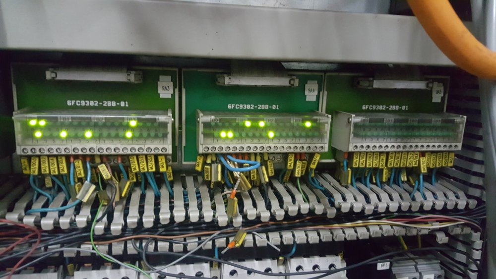
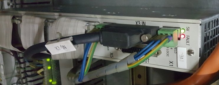
Теперь вернусь к автоматам. Все цепочки — нормальные. На фотографии 1 на модуле 9А3 горят светодиоды B2.7 и B3.0 — т.е. все автоматы нормальные. На фотографии 2 на блоке питания 9А1 постоянно горит красный светодиод FAULT. На фотографии 1 видно, что горят светодиоды на модулях 9А3 и 9А4 (это если мы правильно понимаем, входные цепи для 9А1) и не горят на выходном модуле 9А5. Сам блок 9А1 мы меняли (брали точно такой же с соседнего рабочего станка) — ничего не менялось. X3/IN — это связь с PLC.
4) Ошибка выпадает сразу при загрузке. Я разговаривал с сервисником Шпиннера из Болгарии, он сказал, что все остальные ошибки — это производные от 700004. Завтра сделаю фото области «диагностика».
5) Нет, проекта у меня нет.
Siemens Sinumerik 840D alarm list (840D/840Di/810D and similar controls), for cnc machinists and maintenance personnel who work on cnc machines with Sinumerik cnc controls.

Siemens Sinumerik Alarms
Sinumerik 840D Alarm List
- 1000 System error %1
- 1001 System error %1
- 1002 System error %1
- 1003 Alarm pointer for this self-clearing alarm %1 is zero
- 1004 Alarm reaction to NCK alarm incorrectly configured
- 1005 Operating system error %1 parameter %2 %3 %4
- 1010 Channel %1 system error %2 action %3
- 1011 Channel %1 %3 %4 system error %2
- 1012 Channel %1 system error %2 %3 %4
- 1013 Channel %1 system error %2
- 1014 Channel %1 system error %2
- 1015 Channel %1 axis %2 system error %3
- 1016 Channel %1 axis %2 system error %3
- 1017 Channel %1 axis %2 system error %3
- 1018 Floating point arithmetic error in channel %1 task %2 station %3 FPU state %4 %4
- 1019 Floating point arithmetic error at address %3 in channel %1 task %2 FPU state %4
- 1030 System error in link module error code %1 error type %2
- 1031 Link module generated an unspecified error %1 NCU %2 %3 %4
- 1100 No valid firmware
- 1160 Assertion failed in %1: %2
- 2000 PLC sign-of-life monitoring
- 2001 PLC has not started up
- 2100 NCK battery warning threshold reached
- 2101 NCK battery alarm
- 2102 NCK battery alarm
- 2110 NCK temperature alarm
- 2120 NCK fan alarm
- 2130 5V/24V encoder or 15V D/A converter under voltage
- 2140 The actual service switch position forces a SRAM to be cleared at the next Power On (general reset active)
- 2190 Hardware plug-in module for communication with the digitizer missing
- 2192 No NCU link module exists, MD %1 reset
- 2193 “Safety Integrated” is not available for link axis %1.
- 2195 Channel %1 axis %2 high-speed punching/nibbling not possible via link
- 2196 Link axis active and $MN_MM_SERVO_FIFO_SIZE != %1
- 2900 Reboot is delayed
- 3000 Emergency stop
- 3001 Internal emergency stop
- 4000 Channel %1 machine data %2[%3] has gap in axis assignment
- 4001 Channel %1 axis %2 defined for more than one channel via machine data %3
- 4002 Channel %1 machine data %2[%3] assigns an axis not defined in channel
- 4003 Axis %1 incorrect assignment of master channel in machine data %2
- 4004 Channel %1 machine data %2 axis %3 defined repeatedly as geometry axis
- 4005 Maximum number of axes in channel %1 exceeded. Limit %2
- 4007 Axis %1 incorrect assignment of master NCU in machine data %2
- 4010 Invalid identifier used in machine data %1[%2]
- 4011 Channel %1 invalid identifier used in machine data %2[%3]
- 4012 Invalid identifier used in machine data %1[%2]
- 4013 Invalid NCU link configuration by machine data %1 = %2 , on NCU_1 = %3
- 4014 Axis %1 defined several times in %2
- 4016 Axis %1 already used by NCU %2
- 4017 Axis container %1, location %2 already used by NCU %3
- 4018 Axis container %1, location %2 not used by any channel
- 4019 Axis container %1 advance not allowed with current status of NCU %2
- 4020 Identifier %1 used several times in machine data %2
- 4021 Channel %1 identifier %2 used several times in machine data %3
- 4022 Axis container %3 switch not allowed: ext. zero offset active channel %1 axis %2
- 4023 Axis container %1 switch not allowed, axis container %2 switch active
- 4024 Invalid axis configuration due to missing axis container machine data
- 4025 Axis container %3 switch not allowed: master/slave active channel %1 axis %2
- 4026 Machine data %1[%2], link axis NC%3_AX%4 not used by any channel
- 4027 Notice: MD %1 was also changed for the other axes of axis container %2
- 4028 Notice! The axial MDs of the axes of the axis containers were matched.
- 4029 Notice: the axial MDs in axis container %1 will be matched on the next power-up
- 4030 Channel %1 axis identifier missing in machine data %2[%3]
- 4031 Channel %1 link axis %2 defined for more than one channel in machine data %3
- 4032 Channel %1 wrong identifier for facing axis in %2
- 4033 Notice: NCU link communication still not connected
- 4034 Local link axis %1 is not allowed for different interpolation cycle time = %2/%3
- 4035 Interpolation cycle from NCU%1 = %2 does not match NCU%3 = %4
- 4036 Wrong NCU link configuration by MD %1
- 4040 Channel %1 axis identifier %2 not consistent with machine data %3
- 4045 Channel %1 conflict between machine data %2 and machine data %3
- 4050 NC code identifier %1 cannot be reconfigured to %2
- 4060 Standard machine data loaded
- 4062 Backup data loaded
- 4065 Buffered memory was restored from backup medium (potential loss of data!)
- 4066 Buffered memory of FFS restored from backup medium (potential loss of data!)
- 4070 Normalizing machine data has been altered
- 4073 Compile cycle functions define machine data number %1 several times
- 4075 Machine data %1 (and maybe others) not altered due to missing permission level %2
- 4076 %1 Machine data could not be altered with permission level %2
- 4077 New value %1 of MD %2 not set. Requested %3 bytes too much %4 memory.
- 4080 Incorrect configuration of indexing axis in MD %1
- 4090 Too many errors during power-up
- 4100 System cycle time/scan time divider corrected for digital drive
- 4102 Default values for drive cycle times differ
- 4110 IPO factor increased to %1
- 4111 PLC cycle increased to %1 ms
- 4112 Servo cycle changed to %1 ms
- 4113 Sysclock cycle changed to %1 ms
- 4114 Error in DP cycle of SDB1000
- 4115 Time ratio communication to Ipo changed to %1
- 4150 Channel %1 invalid M function sub program call configured
- 4152 Illegal configuration of the “Block display with absolute values” function
- 4160 Channel %1 invalid M function number configured for spindle switchover
- 4170 Invalid M function number for channel synchronisation assigned
- 4180 Invalid M function number assigned to enable ASUP
- 4181 Channel %1 invalid assignment of an M auxiliary function number
- 4182 Channel %1 invalid M auxiliary function number in %2%3, MD reset
- 4183 Channel %1 M auxiliary function number %2 used several times (%3 and %4)
- 4184 Channel %1 illegally predefined auxiliary function in %2%3, MD reset
- 4185 Channel %1 illegal auxiliary function configured %2 %3 %4
- 4200 Channel %1 geometry axis %2 must not be declared a rotary axis
- 4210 Channel %1 spindle %2 declaration as rotary axis missing
- 4215 Channel %1 spindle %2 declaration as modulo axis missing
- 4220 Channel %1 spindle %2 declared repeatedly
- 4225 Channel %1 axis %2 declaration as rotary axis missing
- 4230 Channel %1 data alteration from external not possible in current channel state
- 4240 Runtime overflow for IPO cycle or position controller cycle, IP %1
- 4250 FastPlcCom functionality not available
- 4252 PLCIO read error: %1
- 4254 PLCIO write error: %1
- 4260 Machine data %1 illegal
- 4270 Machine data %1 assigns not activated NCK input/output byte %2
- 4275 Machine data %1 and %2 both assign the same NCK output byte no. %3 several times
- 4280 Assignment of NCK input/output byte via MD %1[%2] does not match hardware configuration
- 4282 Hardware of external NCK outputs assigned repeatedly
- 4285 Error on terminal block %1, error code %2
- 4290 Local P-bus sign-of-life monitoring
- 4291 Module in local P-bus slot %1 error codes %2 %3 %4 %2 %3 %4
- 4300 Declaration in MD %1 is not allowed for geometry axis/spindle %2.
- 4310 Declaration in MD %1 index %2 is not allowed.
- 4320 Axis %1 function %2 %3 and %4 not allowed
- 4334 Channel %1 The amount of fine correction in parameter %2 of the orientable toolholder %3 is too large
- 4336 Channel %1 orientable toolholder no. %2 for orientation transformation %3 does not exist
- 4338 Channel %1 invalid transformation type ‘%2’ in toolholder %3 for orientation transformer %4
- 4340 Channel %1 block %2 invalid transformation type in transformation no. %3
- 4341 Channel %1 block %2 no data set available for transformation no. %3
- 4342 Channel %1 invalid machine data for general 5-axis transformation error no. %2
- 4343 Channel %1 attempt made to change the machine data of an active transformation.
- 4345 Channel %1 invalid configuration in chained transformation no.%2
- 4346 Channel %1 invalid geoaxis assignment in machine data %2[%3]
- 4347 Channel %1 invalid channel axis assignment in machine data %2[%3]
- 4350 Channel %1 axis identifier %2 machine data %3 not consistent with machine data %4
- 4400 MD alteration will cause reorganisation of buffered memory (loss of data!)
- 4502 Channel %1 anachronism %2(%3) -> %4
- 5000 Communication job not executable %1
- 6000 Memory reorganized using standard machine data
- 6010 Channel %1 data block %2 not or not completely created, error code %3
- 6020 Machine data have been altered – now memory is reorganized
- 6030 Limit of user memory has been adapted
- 6035 Instead of %1 KB the system has only %2 KB of free user memory of type “%3”
- 6100 Error while creating %1, error number %2 %3
- 6401 Channel %1 tool change not possible: Empty location for tool %2 Duplo no. %3 on magazine %4 not available.
- 6402 Channel %1 tool change not possible. Magazine no. %2 not available
- 6403 Channel %1 tool change not possible. Magazine location number %2 on magazine %3 not available.
- 6404 Channel %1 tool change not possible. Tool %2 not available or not usable
- 6405 Channel %1 command %2 has invalid PLC acknowledge parameter %3 – identifier %4
- 6406 Channel %1 PLC acknowledge for command %2 is missing
- 6407 Channel %1 tool %2 cannot be placed in magazine %3 on location %4.Invalid definition of magazine!
- 6410 TO unit %1 tool %2 / Duplo no. %3 has reached its pre warning limit with D = %4
- 6411 Channel %1 tool %2 / Duplo no. %3 has reached its prewarning limit with D = %4
- 6412 TO unit %1 tool %2 / Duplo no. %3 has reached its monitoring limit with D = %4
- 6413 Channel %1 tool %2 / Duplo no. %3 has reached its monitoring limit with D = %4
- 6421 Channel %1 tool move not possible. Empty location for tool %2 Duplo no. %3 on magazine %4 not available.
- 6422 Channel %1 tool move not possible. Magazine no. %2 not available.
- 6423 Channel %1 tool move not possible. Location %2 on magazine %3 not available.
- 6424 Channel %1 tool move not possible. Tool %2 not available/not usable.
- 6425 Channel %1 tool %2 cannot be placed in magazine %3 on location %4. Invalid definition of magazine!
- 6430 Workpiece counter: overflow in table of monitored cutting edges.
- 6431 Function not allowed. Tool management/monitoring is not active.
- 6432 Function not executable. No tool assigned to tool holder/spindle
- 6433 Channel %1 block %2 %3 not available with tool management
- 6434 Channel %1 block %2 NC command SETMTH not allowed because tool holder function not active
- 6441 Writing of $P_USEKT not allowed.
- 6442 Channel %1 function not executable. No tool assigned to desired magazine/magazine location %2.
- 6450 Channel %1 tool change not possible. Invalid magazine location no. %2 in buffer magazine
- 6451 Channel %1 tool change not possible. No buffer magazine defined.
- 6452 Channel %1 tool change not possible. Tool holder/spindle number = %2 not defined.
- 6453 Channel %1 tool change not possible. No assignment between toolholder/spindle no. = %2 and buffer magazine location %3
- 6454 Channel %1 tool change not possible. No distance relation available.
- 6500 NC memory full
- 6510 Too many part programs in the NC memory
- 6520 The value of the machine data %1%2 is too low
- 6530 Too many files in directory
- 6540 Too many directories in the NC memory
- 6550 Too many subdirectories
- 6560 Data format not allowed
- 6570 NC memory full
- 6580 NC memory full
- 6600 NC card memory is full
- 6610 Too many files open on NC card
- 6620 NC card has incorrect format
- 6630 NC card hardware is defective
- 6640 NC card is not inserted
- 6650 Write protection of NC card is active
- 6660 ‘Flash File System’ option is not set
- 6670 NC card read active
- 6671 NC card write active
- 6690 Cycles from NC card cannot be copied to the passive file system.
- 6691 Cycles from the passive file system cannot be saved on the NC card
- 6692 Cycle %1 lost
- 6693 File %1 lost
- 6698 Unknown NC card (%1/%2). Writing not possible.
- 6700 Channel %1 value of the machine data %2%3 is too low
- 7000 Too many compile cycle alarms defined
- 7010 Range of MMC alarm numbers for compile cycles exceeded
- 7020 Compile cycle alarm number has not been defined
- 7100 Compile cycles VDI area: %1 byte for inputs and %2 byte for outputs. Maximum %3 bytes available.
- 7200 Problem with externally linked compile cycle %1 %2
- 7201 Assertion error in %1 line %2
- 7202 Missing option bit for %1: %2
- 8000 Channel %1 option ‘user interrupt programs’ not set
- 8010 Option ‘activation of more than %1 axes’ not set
- 8020 Option ‘activation of more than %1 channels’ not set
- 8021 Option ‘activation of more than %1 mode groups’ not set
- 8022 Option ‘activation of more than %1KB SRAM’ not set
- 8030 Channel %1 block %2 option ‘interpolation of more than 4 axes’ not set
- 8032 Option ‘activation of more than %1 link axes’ not set
- 8034 Option ‘activation of axis containers’ not set
- 8036 Option: it is not allowed to set different IPO cycles or position control cycles with NCU link.
- 8038 Option ‘activation of more than %1 lead link axes’ not set
- 8040 Machine data %1 reset, corresponding option is not set
- 8041 Axis %1: MD %2 reset, corresponding option not sufficient
- 8044 Option for IPO cycle time %1 ms not set
- 8045 Option for selected cycle settings not set
- 8080 %1 options are activated without setting the license key
- 8081 %1 options are activated that are not licensed by the license key
- 8082 The license key was entered three times, Power On required before next try.
- 8098 Invalid combination of options (%1)
- 8100 Channel %1 block %2: function not possible
- 10203 Channel %1 NC start without reference point
- 10207 Channel %1 error when selecting or deselecting the digitize function
- 10208 Channel %1 continue program with NC start
- 10209 Channel %1 internal NC stop after block search
- 10222 Channel %1 inter-channel communication not possible
- 10223 Channel %1: Command %2 is already occupied
- 10225 Channel %1: command denied
- 10299 Channel %1 Auto-Repos function is not enabled
- 10600 Channel %1 block %2 auxiliary function during thread cutting active
- 10601 Channel %1 block %2 zero velocity at block end point during thread cutting
- 10604 Channel %1 block %2 thread lead increase too high
- 10605 Channel %1 block %2 thread lead decrease too high
- 10607 Channel %1 block %2 thread with frame not executable
- 10610 Channel %1 axis %2 not stopped
- 10620 Channel %1 block %3 axis %2 at software limit switch %4
- 10621 Channel %1 axis %2 rests on software limit switch %3
- 10630 Channel %1 block %2 axis %3 at working area limit %4
- 10631 Channel %1 axis %2 rests at working area limit %3
- 10650 Channel %1 axis %2 incorrect gantry machine data, error code %3
- 10651 Channel %1 illegal gantry configuration. Error code %2
- 10652 Channel %1 axis %2 gantry warning threshold exceeded
- 10653 Channel %1 axis %2 gantry error threshold exceeded
- 10654 Channel %1 waiting for synchronization start of gantry group %2
- 10655 Channel %1 synchronization of gantry group %2 in progress
- 10656 Channel %1 axis %2 gantry alarm not yet used
- 10700 Channel %1 block %2 NCK protection zone %3 violated during automatic or MDA mode
- 10701 Channel %1 block %2 channel-specific protection zone %3 violated during automatic or MDA mode
- 10702 Channel %1 NCK protection zone %2 violated during manual mode
- 10703 Channel %1 channel-specific protection zone %2 violated during manual mode
- 10704 Channel %1 block %2 protection zone monitoring is not guaranteed
- 10706 Channel %1 NCK protection zone %2 reached with axis %3 during manual mode
- 10707 Channel %1 channel-specific protection zone %2 reached with axis %3 during manual mode
- 10710 Channel %1 block %2 conflict with centre less grinding
- 10720 Channel %1 block %3 axis %2 software limit switch %4
- 10721 Channel %1 block %3 axis %2 software limit switch %4
- 10730 Channel %1 block %3 axis %2 working area limitation %4
- 10731 Channel %1 block %3 axis %2 working area limitation %4
- 10740 Channel %1 block %2 too many empty blocks in WAB programming
- 10741 Channel %1 block %2 direction reversal with WAB infeed motion
- 10742 Channel %1 block %2 WAB distance invalid or not programmed
- 10743 Channel %1 block %2 WAB programmed several times
- 10744 Channel %1 block %2 no valid WAB direction defined
- 10745 Channel %1 block %2 WAB end position not clear
- 10746 Channel %1 block %2 block search stop for WAB
- 10747 Channel %1 block %2 retraction direction not defined for WAB
- 10748 Channel %1 block %2 illegal retract plane with WAB
- 10750 Channel %1 block %2 tool radius compensation activated without tool number
- 10751 Channel %1 block %2 danger of collision due to tool radius compensation
- 10752 Channel %1 block %2 overflow of local block buffer with tool radius compensation
- 10753 Channel %1 block %2 selection of the tool radius compensation only possible in linear block
- 10754 Channel %1 block %2 deselection of the tool radius compensation only possible in linear block
- 10755 Channel %1 block %2 selection of the tool radius compensation via KONT not possible at the current starting point
- 10756 Channel %1 block %2 deselection of the tool radius compensation via KONT not possible at the programmed end point
- 10757 Channel %1 block %2 changing the compensation plane while tool radius compensation is active not possible
- 10758 Channel %1 block %2 curvature radius with variable compensation value too small
- 10759 Channel %1 block %2 path is parallel to tool orientation
- 10760 Channel %1 block %2 helical axis is not parallel to tool orientation
- 10761 Channel %1 block %2 tool radius compensation for ellipse with more than one revolution not possible
- 10762 Channel %1 block %2 too many empty blocks between two traversing blocks with active tool radius compensation
- 10763 Channel %1 block %2 path component of the block in the compensation plane becomes zero
- 10764 Channel %1 block %2 discontinuous path with active tool radius compensation
- 10765 Channel %1 block %2 3D tool radius compensation not possible
- 10766 Channel %1 illegal change of surface orientation between block %2 and block %3
- 10767 Channel %1 block %2 processing with tilt angle unequal 0 not possible
- 10768 Channel %1 block %2 illegal tool orientation with 3D tool radius compensation
- 10769 Channel %1 block %2 Illegal surface normal vector with 3D tool radius compensation
- 10770 Channel %1 block %2 change of corner type due to change of orientation with active tool radius compensation
- 10771 Channel %1 block %2 overflow of local block buffer due to orientation smoothing
- 10772 Channel %1 block %2 illegal orientation change when activating or deactivating 3D face cutting
- 10773 Channel %1 illegal tool orientation in block %2 at inside corner with block %3
- 10774 Channel %1 illegal tool dimensions with face cutting in block %2
- 10775 Channel %1 illegal tool change with face cutting in block %2
- 10776 Channel %1 block%2 axis %3 must be geometry axis if tool radius compensation is active
- 10777 Channel %1 block %2 tool radius compensation: too many blocks with suppression of compensation
- 10778 Channel %1 block %2 preprocessing stop with active tool radius compensation
- 10779 Channel %1 block %2 preprocessing stop with active tool radius compensation
- 10780 Channel %1 block %2 preprocessing stop with active tool radius compensation
- 10781 Channel %1 block %2 illegal orientation of involute with tool radius compensation
- 10782 Channel %1 block %2 illegal curve type with tool radius compensation
- 10783 Channel %1 block %2 tool radius compensation type requires orientation transformation
- 10784 Channel %1 block %2 illegal tool for tool radius compensation with constraint surface
- 10790 Channel %1 block %2 plane change during linear programming with angles
- 10791 Channel %1 block %2 invalid angle during linear programming
- 10792 Channel %1 block %2 illegal interpolation type during linear programming with angles
- 10793 Channel %1 block %2 second block missing during linear programming with angles
- 10794 Channel %1 block %2 angle specification missing in second block during linear interpolation with angles
- 10795 Channel %1 block %2 end point specification during angle programming contradictory
- 10800 Channel %1 block %3 axis %2 is not a geometry axis
- 10805 Channel %1 block %2 repositioning after switch of geometry axes or transformation
- 10810 Channel %1 block %2 master spindle not defined
- 10820 Channel %1 rotary axis/spindle %2 not defined
- 10860 Channel %1 block %2 feedrate not programmed
- 10861 Channel %1 block %3 velocity of positioning axis %2 is zero
- 10862 Channel %1 block %2 master spindle also used as path axis
- 10870 Channel %1 block %2 facing axis not defined
- 10880 Channel %1 block %2 too many empty blocks between two traversing blocks when inserting chamfers or radii
- 10881 Channel %1 block %2 overflow of local block buffer when inserting chamfers or radii
- 10882 Channel %1 block %2 activation of chamfers or radii (non-modal) without traversing movement in the block
- 10883 Channel %1 block %2 chamfer or fillet has to be reduced
- 10890 Channel %1 block %2 overflow of local block buffer when calculating splines
- 10891 Channel %1 block %2 multiplicity of node is greater than its order
- 10900 Channel %1 block %2 no S value programmed for constant cutting speed
- 10910 Channel %1 block %2 excessive velocity of one path axis
- 10911 Channel %1 block %2 transformation prohibits to traverse the pole
- 10912 Channel %1 block %2 preprocessing and main run might not be synchronized
- 10913 Channel %1 block %2 negative feed profile is ignored
- 10914 Movement not possible while transformation active – in channel %1, block %2
- 10930 Channel %1 block %2 interpolation type not allowed in stock removal contour
- 10931 Channel %1 block %2 incorrect stock removal contour
- 10932 Channel %1 block %2 preparation of contour has been restarted
- 10933 Channel %1 block %2 contour program does not contain enough contour blocks
- 10934 Channel %1 block %2 array for contour segmentation is set too small
- 10940 Channel %1 block %2 curve table %3: delete/overwrite not possible
- 10941 Channel %1 block %2 curve table %3: NC memory full
- 10942 Channel %1 block %2 curve table %3: illegal instruction during definition
- 10943 Channel %1 block %2 curve table %3: direction reversal of lead value in the block not allowed
- 10944 Channel %1 block %2 curve table %3: illegal transformation
- 10945 Channel %1 block %2 curve table %3: illegal coupling of axes
- 10946 Channel %1 block %2 curve table %3: no contour defined
- 10947 Channel %1 block %2 curve table %3: contour not continuous
- 10948 Channel %1 block %2 curve table %3: position jump at end of period
- 10949 Channel %1 block %2 curve table %3: missing master axis motion
- 10950 Channel %1 calculation of arc length function too inaccurate
- 10951 Channel %1 block %2 curve table %3: following value period is zero
- 10955 Channel %1 block %2 curve table %3: missing master axis motion
- 10956 Channel %1 block %2 curve table %3: NC memory limit DRAM reached
- 10960 Channel %1 block %2 COMPCURV/COMPCAD and radius compensation cannot be used simultaneously
- 10961 Channel %1 block %2 maximum cubic polynomials are allowed on active radius compensation.
- 10962 Channel %1 block %2 function %3 not possible with path correction
- 12000 Channel %1 block %2 address %3 programmed repeatedly
- 12010 Channel %1 block %2 address %3 address type programmed too often
- 12020 Channel %1 block %2 illegal address modification
- 12030 Channel %1 block %2 invalid parameter or data type in %3
- 12040 Channel %1 block %2 expression %3 is not of data type ‘AXIS’
- 12050 Channel %1 block %2 DIN address %3 not configured
- 12060 Channel %1 block %2 same G group programmed repeatedly
- 12070 Channel %1 block %2 too many syntax-defining G functions
- 12080 Channel %1 block %2 syntax error in text %3
- 12090 Channel %1 block %2 unexpected parameter %3
- 12100 Channel %1 block %2 number of passes %3 not permissible
- 12110 Channel %1 block %2 block syntax cannot be interpreted
- 12120 Channel %1 block %2 G function not separately programmed
- 12130 Channel %1 block %2 illegal tool orientation
- 12140 Channel %1 block %2 functionality %3 not implemented
- 12150 Channel %1 block %2 operation %3 not compatible with data type
- 12160 Channel %1 block %2 range of values exceeded
- 12170 Channel %1 block %2 identifier %3 defined repeatedly
- 12180 Channel %1 block %2 illegal chaining of operators %3
- 12190 Channel %1 block %2 variable of type ARRAY has too many dimensions
- 12200 Channel %1 block %2 symbol %3 cannot be created
- 12210 Channel %1 block %2 string %3 too long
- 12220 Channel %1 block %2 binary constant %3 in string too long
- 12230 Channel %1 block %2 hexadecimal constant %3 in string too long
- 12240 Channel %1 block %2 tool orientation %3 defined repeatedly
- 12250 Channel %1 block %2 nested macro %3 not possible
- 12260 Channel %1 block %2 too many initialization values specified %3
- 12261 Channel %1 block %2 initialization of %3 not allowed
- 12270 Channel %1 block %2 macro identifier %3 already defined
- 12280 Channel %1 block %2 maximum macro length %3 exceeded
- 12290 Channel %1 block %2 arithmetic variable % 3 not defined
- 12300 Channel %1 block %2 call-by-reference parameter missing on subroutine call %3
- 12310 Channel %1 block %2 axis parameter missing on procedure call %3
- 12320 Channel %1 block %2 parameter %3 is no variable
- 12330 Channel %1 block %2 type of parameter %3 incorrect
- 12340 Channel %1 block %2 number of parameters too high %3
- 12350 Channel %1 block %2 parameter %3 no longer possible
- 12360 Channel %1 block %2 dimension of parameter %3 incorrect
- 12370 Channel %1 block %2 range of values %3 not permissible
- 12380 Channel %1 block %2 maximum memory capacity reached
- 12390 Channel %1 block %2 initialization value %3 cannot be converted
- 12400 Channel %1 block %2 field %3 element does not exist
- 12410 Channel %1 block %2 incorrect index type for %3
- 12420 Channel %1 block %2 identifier %3 too long
- 12430 Channel %1 block %2 specified index is invalid
- 12440 Channel %1 block %2 maximum number of formal arguments exceeded
- 12450 Channel %1 block %2 label defined twice
- 12460 Channel %1 block %2 maximum number of symbols exceeded with %3
- 12470 Channel %1 block %2 G function %3 is unknown
- 12475 Channel %1 block %2 invalid G function number %3 programmed
- 12480 Channel %1 block %2 subroutine %3 already defined
- 12490 Channel %1 block %2 access permission level %3 is not valid
- 12500 Channel %1 block %2 in this module %3 is not possible
- 12510 Channel %1 block %2 too many machine data %3
- 12520 Channel %1 block %2 too many tool parameters %3
- 12530 Channel %1 block %2 invalid index for %3
- 12540 Channel %1 block %2 Block is too long or too complex
- 12550 Channel %1 block %2 name %3 not defined or option not installed
- 12552 Channel %1 block %2 tool/magazine OEM parameter not defined. Option not set.Option not set.
- 12560 Channel %1 block %2 programmed value %3 exceeds allowed limits
- 12570 Channel %1 block %2 too many motion synchronous actions in %3
- 12571 Channel %1 block %2 %3 not permissible for motion synchronous action
- 12572 Channel %1 block %2 %3 only permissible for motion synchronous action
- 12580 Channel %1 block %2 %3 not permissible for assignment in motion synchronous action
- 12581 Channel %1 block %2 invalid read access to %3 while in motion synchronous action
- 12582 Channel %1 block %2 field index %3 incorrect
- 12583 Channel %1 block %2 variable %3 no system variable
- 12584 Channel %1 block %2 variable %3 cannot be read synchronously with motion
- 12585 Channel %1 block %2 variable %3 cannot be changed synchronously with motion
- 12586 Channel %1 block %2 motion synchronous action: type conflict in variable %3
- 12587 Channel %1 block %2 motion synchronous action: operation/function %3 not allowed
- 12588 Channel %1 block %2 motion synchronous action: address %3 not allowed
- 12589 Channel %1 block %2 motion synchronous action: variable %3 not allowed with modal ID
- 12590 Channel %1 block %2 global user data cannot be created
- 12600 Channel %1 block %2 invalid line checksum
- 12610 Channel %1 block %2 accessing single character with call-by-reference parameter not possible %3
- 12620 Channel %1 block %2 accessing this variable as single character not possible
- 12630 Channel %1 block %2 skip ID/label in control structure not allowed
- 12640 Channel %1 block %2 invalid nesting of control structures
- 12641 Channel %1 block %2 maximum nesting depth of control structures exceeded
- 12650 Channel %1 block %2 axis identifier %3 different in channel %4
- 12660 Channel %1 block %2 motion synchronous action: variable %3 reserved for motion synchronous actions and technology cycles
- 12661 Channel %1 block %2 technology cycle %3: no further subprogram call possible
- 12700 Channel %1 block %2 contour definition programming not allowed as modal sub program is active
- 12701 Channel %1 block %2 illegal interpolation type for contour definition active
- 12710 Channel %1 block %2 illegal language element in external language mode
- 12720 Channel %1 block %2 program number for macro call (G65/G66) missing
- 12722 Channel %1 block %2 multiple ISO_2/3 macro or cycle calls in the block
- 12724 Channel %1 block %2 no radius programmed for cylinder interpolation activation/deactivation
- 12726 Channel %1 block %2 illegal plane selection with parallel axes
- 12728 Channel %1 block %2 distance for double turret not set
- 12730 Channel %1 block %2 no valid transformation machine data parametrized
- 12740 Channel %1 block %2 modal macro call %3 not possible
- 14000 Channel %1 block %2 illegal end of file
- 14001 Channel %1 block %2 illegal end of block
- 14009 Channel %1 block %2 illegal program path %3
- 14010 Channel %1 block %2 invalid default parameter in subroutine call
- 14011 Channel %1 block %2 program %3 not existing or will be edited
- 14012 Channel %1 block %2 maximum subroutine level exceeded
- 14013 Channel %1 block %2 number of subroutine passes invalid
- 14014 Channel %1 selected program %3 not available or will be edited
- 14015 Channel %1 block %2 program %3 is not enabled
- 14016 Channel %1 block %2 error when calling the subroutine via M/T function
- 14017 Channel %1 block %2 syntax error when calling the subroutine via M function
- 14020 Channel %1 block %2 wrong value or wrong number of parameters on function or procedure call
- 14021 Channel %1 block %2 wrong value or wrong number of parameters on function or procedure call
- 14025 Channel %1 block %2 motion synchronous action: illegal modal ID
- 14026 Channel %1 block %2 motion synchronous action: invalid polynomial number in the FCTDEF command
- 14030 Channel %1 block %2 combine OSCILL and POSP during oscillation with in feed motion
- 14033 Channel %1 block %2 involute: no end point programmed
- 14034 Channel %1 block %2 involute: angle of rotation too large
- 14035 Channel %1 block %2 involute: start point invalid
- 14036 Channel %1 block %2 involute: end point invalid
- 14037 Channel %1 block %2 involute: radius invalid
- 14038 Channel %1 block %2 involute not definable: end point error
- 14039 Channel %1 block %2 involute: end point programmed several times
- 14040 Channel %1 block %2 error in end point of circle
- 14045 Channel %1 block %2 error in tangential circle programming
- 14048 Channel %1 block %2 wrong number of revolutions in circle programming
- 14050 Channel %1 block %2 nesting depth for arithmetic operations exceeded
- 14051 Channel %1 block %2 arithmetic error in part program
- 14060 Channel %1 block %2 invalid skip level with differential block skip
- 14070 Channel %1 block %2 memory for variables not sufficient for subroutine call
- 14080 Channel %1 block %2 jump destination %3 not found
- 14082 Channel %1 block %2 label %3 program section not found
- 14085 Channel %1 block %2 instruction not allowed
- 14088 Channel %1 block %2 axis %3 doubtful position
- 14090 Channel %1 block %2 illegal D number
- 14091 Channel %1 block %2 illegal function, index %3 %3
- 14092 Channel %1 block %2 axis %3 is wrong axis type
- 14093 Channel %1 block %2 path interval <= 0 with polynominal interpolation
- 14094 Channel %1 block %2 polynominal degree greater than 3 programmed for polynominal interpolation
- 14095 Channel %1 block %2 radius for circle programming too small
- 14096 Channel %1 block %2 illegal type conversion
- 14097 Channel %1 block %2 string cannot be converted to AXIS type
- 14098 Channel %1 block %2 conversion error: no valid number found
- 14099 Channel %1 block %2 result in string concatenation too long
- 14100 Channel %1 block %2 orientation transformation not available
- 14101 Channel %1 block %2 orientation transformation not active
- 14102 Channel %1 block %2 polynominal degree greater than 5 programmed for orientation vector angle
- 14110 Channel %1 block %2 Euler angles and orientation vector components programmed
- 14111 Channel %1 block %2 Euler angles, orientation vector and transformation axes programmed
- 14112 Channel %1 block %2 programmed orientation path not possible
- 14113 Channel %1 block %2 programmed lead angle too large
- 14114 Channel %1 block %2 programmed tilt angle too large
- 14115 Channel %1 block %2 illegal definition of workpiece surface
- 14116 Channel %1 block %2 absolute orientation programmed while ORIPATH is active
- 14117 Channel %1 block %2 no angle or direction of the cone programmed
- 14118 Channel %1 block %2 no end orientation programmed
- 14119 Channel %1 block %2 no intermediate orientation programmed
- 14120 Channel %1 block %2 plane determination for programmed orientation not possible
- 14122 Channel %1 block %2 angle and direction of the cone programmed
- 14123 Channel %1 block %2 nutation angle of the cone too small
- 14124 Channel %1 block %2 start tangent for orientation is zero
- 14125 Channel %1 block %2 programmed rotation is not possible
- 14129 Channel %1 block %2 orientation angles and orientation vector components programmed
- 14130 Channel %1 block %2 too many initialization values given
- 14131 Channel %1 block %2 orientation axes and lead/tilt angles programmed
- 14132 Channel %1 block %2 orientation axes incorrectly configured
- 14133 Channel %1 block %2 G code for orientation definition not allowed
- 14134 Channel %1 block %2 G code for orientation interpolation not allowed
- 14140 Channel %1 block %2 position programming without transformation not allowed
- 14144 Channel %1 block %2 PTP movement not allowed
- 14146 Channel %1 block %2 CP or PTP movement without transformation not allowed
- 14148 Channel %1 illegal reference system for Cartesian manual traverse
- 14150 Channel %1 block %2 illegal tool carrier number programmed or declared (MD)
- 14151 Channel %1 block %2 illegal tool carrier rotation
- 14152 Channel %1 block %2 tool carrier: invalid orientation. Error code: %3
- 14153 Channel %1 block %2 unknown tool carrier type: %3
- 14154 Channel %1 block %2 The amount of fine correction in parameter %3 of the orientable tool holder %4 is too large
- 14155 Channel %1 block %2 invalid base frame definition for tool carrier offset
- 14156 Channel %1 toolholder selection error at reset
- 14157 Channel %1 block %2 illegal interpolation type with MOVT
- 14159 Channel %1 block %2 more than two angles programmed with ROTS or AROTS
- 14160 Channel %1 block %2 tool length selection without geometry axis specification
- 14165 Channel %1 block %2 active T number does not match selected tool
- 14170 Channel %1 block %2 illegal interpolation type with tool length compensation
- 14180 Channel %1 block %2 H number is not defined
- 14185 Channel %1 block %2 D number is not defined
- 14190 Channel %1 block %2 H number with G49
- 14195 Channel %1 block %2 D number with G49
- 14197 Channel %1 block %2 D number and H number programmed simultaneously
- 14198 Channel %1 block %2 illegal change of tool direction with tool offset
- 14199 Channel %1 block %2 illegal plane change for tool with diameter component
- 14200 Channel %1 block %2 negative polar radius
- 14210 Channel %1 block %2 polar angle too large
- 14250 Channel %1 block %2 negative pole radius
- 14260 Channel %1 block %2 pole angle too large
- 14270 Channel %1 block %2 pole programmed incorrectly
- 14280 Channel %1 block %2 polar coordinates programmed incorrectly
- 14290 Channel %1 block %2 poly nominal degree greater than 5 programmed for poly nominal interpolation
- 14300 Channel %1 block %2 overlaid handwheel motion activated incorrectly
- 14310 Handwheel %1 configuration incorrect or inactive
- 14400 Channel %1 block %2 tool radius compensation active at transformation switchover
- 14401 Channel %1 block %2 transformation not available
- 14402 Channel %1 block %2 spline active at transformation change
- 14403 Channel %1 block %2 preprocessing and main run might not be synchronized
- 14404 Channel %1 block %2 illegal parametrization of transformation
- 14410 Channel %1 block %2 spline active at geometry axis changeover
- 14411 Channel %1 block %2 tool radius compensation active at geometry axis changeover
- 14412 Channel %1 block %2 transformation active at geometry axis changeover
- 14413 Channel %1 block %2 fine tool correction: changeover geometry/channel axis not allowed
- 14414 Channel %1 block %2 GEOAX function: incorrect call
- 14415 Channel %1 block %2 tangent control: changeover geometry/channel axis not allowed
- 14420 Channel %1 block %2 index axis %3 frame not allowed
- 14500 Channel %1 block %2 illegal DEF or PROC instruction in the part program
- 14510 Channel %1 block %2 PROC instruction missing on subroutine call
- 14520 Channel %1 block %2 illegal PROC instruction in data definition section
- 14530 Channel %1 block %2 EXTERN and PROC instruction do not correspond
- 14600 Channel %1 block %2 reload buffer %3 cannot be established
- 14601 Channel %1 block %2 reload buffer could not be deleted
- 14602 Channel %1 block %2 timeout during EXTCALL
- 14610 Channel %1 block %2 compensation block not possible
- 14650 Channel %1 block %2 SETINT instruction with invalid ASUP input
- 14660 Channel %1 block %2 SETINT instruction with invalid priority
- 14700 Channel %1 block %2 timeout during command to interpreter
- 14701 Channel %1 block %2 number of available NC blocks reduced by %3
- 14710 Channel %1 block %2 error in initialization sequence in function %3
- 14720 Channel %1 block %2 axes for centerless transformation not available
- 14730 Channel %1 block %2 conflict at activation of centerless transformation
- 14740 Channel %1 block %2 no tool data available for centerless grinding
- 14745 Channel %1 block %2 centerless grinding not active
- 14750 Channel %1 block %2 too many auxiliary functions programmed
- 14751 Channel %1 block %2 resources for motion synchronous actions not sufficient (code: %3)
- 14752 Channel %1 block %2 DELDTG | STOPREOF conflict
- 14753 Channel %1 block %2 motion synchronous actions with illegal interpolation type
- 14754 Channel %1 block %2 motion synchronous actions and wrong feed type
- 14755 Channel %1 block %2 motion synchronous actions without traverse motion
- 14756 Channel %1 block %2 motion synchronous action and wrong value
- 14757 Channel %1 block %2 motion synchronous action and wrong type
- 14758 Channel %1 block %2 programmed value not available
- 14759 Channel %1 block %2 motion synchronous action and wrong axis type
- 14760 Channel %1 block %2 auxiliary function of a group programmed repeatedly
- 14761 Channel %1 block %2 motion synchronous action: DELDTG function not allowed with active tool radius compensation
- 14762 Channel %1 block %2 too many PLC variables programmed
- 14763 Channel %1 block %2 too many link variables programmed
- 14764 NCU link cannot transfer all link variables immediately
- 14765 NCU link cannot transfer all link variables
- 14766 NCU link is heavily loaded, impending memory shortage
- 14767 Machine data matching via NCU link not complete
- 14770 Channel %1 block %2 auxiliary function programmed incorrectly
- 14780 Channel %1 block %2 unreleased option used
- 14790 Channel %1 block %2 axis %3 programmed by PLC
- 14800 Channel %1 block %2 programmed path speed less or equal to zero
- 14810 Channel %1 block %2 negative axis speed programmed for positioning axis %3
- 14811 Channel %1 block %2 incorrect value range for acceleration of axis/spindle %3
- 14812 Channel %1 block %2 SOFTA not available for axis %3
- 14815 Channel %1 block %2 negative thread lead change programmed
- 14820 Channel %1 block %2 negative value for maximum spindle speed programmed with constant cutting speed
- 14821 Channel %1 block %2 error in selection or deselection of GWPS
- 14822 Channel %1 block %2 incorrect programming of GWPS
- 14823 Channel %1 block %2 error on selection or deselection of tool monitoring
- 14824 Channel %1 block %2 conflict with GWPS
- 14840 Channel %1 block %2 incorrect value range for constant cutting speed
- 14900 Channel %1 block %2 center point and end point programmed simultaneously
- 14910 Channel %1 block %2 invalid angle of aperture for programmed circle
- 14920 Channel %1 block %2 intermediate point of circle incorrect
- 15000 Channel %1 block %2 channel-sync instruction using illegal mark
- 15010 Channel %1 block %2 program coordination instruction with invalid channel number
- 15020 Channel %1 block %2 CHANDATA instruction cannot be executed. Channel %3 is not active
- 15021 Channel %1 block %2 CHANDATA instruction with invalid channel number
- 15025 CHANDATA(%2): channel is not active. Channel data will be ignored.
- 15030 Channel %1 block %2 different measurement system settings
- 15100 Channel %1 block %2 REORG abort caused by log file overflow
- 15110 Channel %1 block %2 REORG not possible
- 15150 Channel %1 block %2 reload from external aborted
- 15160 Channel %1 block %2 wrong preprocessing configuration
- 15165 Channel %1 block %2 error when translating or interpreting PLC Asup %3
- 15166 Channel %1 user system asup _N_ASUP_SPF not available
- 15170 Channel %1 block %2 program %3 could not be compiled
- 15171 Channel %1 block %2 compiled program %3 older than the relevant subroutine
- 15175 Channel %1 block %2 program %3. Interfaces could not be built
- 15180 Channel %1 block %2 program %3 cannot be executed as INI file
- 15185 Channel %1 %2 errors in INI file
- 15190 Channel %1 block %2 not enough free memory for subroutine call
- 15300 Channel %1 block %2 invalid number-of-passed-blocks during block search
- 15310 Channel %1 block %2 file requested during block search is not available
- 15320 Channel %1 block %2 invalid block search command
- 15330 Channel %1 block %2 invalid block number as search target
- 15340 Channel %1 block %2 invalid label as search target
- 15350 Channel %1 block %2 search target not found
- 15360 Channel %1 illegal target of block search (syntax error)
- 15370 Channel %1 target of block search not found
- 15380 Channel %1 block %2 illegal incremental programming in axis %3
- 15390 Channel %1 block %2 %3 not executed during block search
- 15395 Channel %1 master-slave not executable during block search
- 15400 Channel %1 block %2 selected initial init file does not exist
- 15410 Channel %1 block %2 initialization file contains invalid M function
- 15420 Channel %1 block %2 instruction in current mode not allowed
- 15450 Channel %1 block %2 compiled program cannot be stored
- 15460 Channel %1 block %2 syntax error with modal function
- 15500 Channel %1 block %2 illegal angle of shear
- 15700 Channel %1 block %2 illegal cycle alarm number %3
- 15800 Channel %1 block %2 wrong starting conditions for CONTPRON/CONTDCON
- 15810 Channel %1 block %2 wrong array dimension for CONTPRON/CONTDCON
- 15900 Channel %1 block %2 touch probe not allowed
- 15910 Channel %1 block %2 touch probe not allowed
- 15950 Channel %1 block %2 no traverse motion programmed
- 15960 Channel %1 block %2 no traverse motion programmed
Pages: 1 2 3