
Sinumerik Alarm 16906 Channel %1 program control: action %2 is aborted due to an alarm
Parameters:
%1 = Channel number
%2 = Action number/action name
Definitions:
The action was aborted due to an alarm.
Reactions:
– Alarm display.
Remedy:
Eliminate the error and acknowledge the alarm. Then repeat the operation.
Program Continuation:
Clear alarm with the Delete key or NC START.
References
- Siemens Diagnostics Guide by Siemens
Sinumerik Alarm 16906 Channel %1 program control: action %2 is aborted due to an alarm
Автор:
Нанософт разработка · Опубликовано: только что
Конференция «Цифровая индустрия промышленной России» («ЦИПР») входит в пятерку крупнейших мероприятий в области цифровой экономики России. На этом масштабном форуме ведущие российские компании представляют свои разработки для цифровой трансформации ключевых отраслей и предприятий страны.
На сессии «Стройкомплекс будущего: вызовы и перспективы цифровой трансформации» исполнительный директор «Нанософт» Максим Егоров рассказал о новых проектах компании. В частности, был представлен программный продукт NSR NormaCS Specification. Эта система, не имеющая аналогов в России, осуществляет автоматический подбор нормативных требований при работе с BIM-моделью, способствуя эволюционному переходу в части технического регулирования. Для реализации задачи разработан искусственный интеллект, который уже сейчас умеет работать с нормативным текстом.
Почетные гости «ЦИПР 2023», Председатель Правительства РФ Михаил Мишустин и Заместитель Председателя Правительства РФ Дмитрий Чернышенко, при знакомстве с выставочной экспозицией высоко оценили Платформу nanoCAD и разработку компании «СиСофт Девелопмент» – систему Model Studio CS.
«Фактически мы импортозаместили все то, что необходимо для проектирования, а именно наша компания, которая сделала продукт nanoCAD, и вставили эту технологию проектирования в стройку. Это важно. Это тот элемент, о котором мы и не мечтали два года назад», – отметил Михаил Мишустин, осматривая цифровой двойник кампуса, реализованный с использованием технологий компании «Нанософт».
По итогам конференции Председатель Правительства РФ дал ряд поручений для дальнейшего развития IT-отрасли России. Он поблагодарил за работу всех участников мероприятия, но отметил, что сейчас доля отечественных разработок составляет около 20%, и призвал не копировать западные технологии, а развивать собственные решения.
О компании «Нанософт»
«Нанософт» – российский разработчик инженерного ПО: технологий автоматизированного проектирования (CAD/САПР), информационного моделирования (BIM/ТИМ) и сопровождения объектов промышленного и гражданского строительства (ПГС) на всех этапах жизненного цикла, а также сквозной цифровизации всех процессов в производстве.
Миссия компании – формирование условий для массового оснащения российского рынка лицензионными, качественными и доступными отечественными программными продуктами. «Нанософт» помогает своим заказчикам достичь импортонезависимости в области инженерного ПО и нацелен на развитие собственных технологий в фокусе реальных потребностей. Это позволяет гарантированно защитить критически важную ИТ-инфраструктуру, что особенно актуально сейчас, когда западные вендоры уходят с рынка, замораживают поставки ПО и техническую поддержку.
Все программные продукты компании включены в Единый реестр российских программ для электронных вычислительных машин и баз данных.
Официальный сайт: nanocad.ru.
О конференции ЦИПР
ЦИПР (Цифровая индустрия промышленной России) – первая в России конференция для глобального диалога и кооперации государства и бизнеса по вопросам развития цифровой экономики, цифровой трансформации промышленности, реализации национальной программы «Цифровая экономика Российской Федерации», развития российского высокотехнологичного экспорта, кибербезопасности.
Официальный сайт: cipr.ru.
1001 System error %1
1002 System error %1
1003 Alarm pointer for this self-clearing alarm %1 is zero
1004 Alarm reaction to NCK alarm incorrectly configured
1005 Operating system error %1 parameter %2 %3 %4
1010 Channel %1 system error %2 action %3
1011 Channel %1 %3 %4 system error %2
1012 Channel %1 system error %2 %3 %4
1013 Channel %1 system error %2
1014 Channel %1 system error %2
1015 Channel %1 axis %2 system error %3
1016 Channel %1 axis %2 system error %3
1017 Channel %1 axis %2 system error %3
1018 Floating point arithmetic error in channel %1 task %2 station %3 FPU state %4 %4
1019 Floating point arithmetic error at address %3 in channel %1 task %2 FPU state %4
1030 System error in link module error code %1 error type %2
1031 Link module generated an unspecified error %1 NCU %2 %3 %4
1100 No valid firmware
1160 Assertion failed in %1: %2
2000 PLC sign-of-life monitoring
2001 PLC has not started up
2100 NCK battery warning threshold reached
2101 NCK battery alarm
2102 NCK battery alarm
2110 NCK temperature alarm
2120 NCK fan alarm
2130 5V/24V encoder or 15V D/A converter under voltage
2140 The actual service switch position forces a SRAM to be cleared at the next Power On (general reset active)
2190 Hardware plug-in module for communication with the digitizer missing
2192 No NCU link module exists, MD %1 reset
2193 Safety Integrated is not available for link axis %1.
2195 Channel %1 axis %2 high-speed punching/nibbling not possible via link
2196 Link axis active and $MN_MM_SERVO_FIFO_SIZE != %1
2900 Reboot is delayed
3000 Emergency stop
3001 Internal emergency stop
4000 Channel %1 machine data %2[%3] has gap in axis assignment
4001 Channel %1 axis %2 defined for more than one channel via machine data %3
4002 Channel %1 machine data %2[%3] assigns an axis not defined in channel
4003 Axis %1 incorrect assignment of master channel in machine data %2
4004 Channel %1 machine data %2 axis %3 defined repeatedly as geometry axis
4005 Maximum number of axes in channel %1 exceeded. Limit %2
4007 Axis %1 incorrect assignment of master NCU in machine data %2
4010 Invalid identifier used in machine data %1[%2]
4011 Channel %1 invalid identifier used in machine data %2[%3]
4012 Invalid identifier used in machine data %1[%2]
4013 Invalid NCU link configuration by machine data %1 = %2 , on NCU_1 = %3
4014 Axis %1 defined several times in %2
4016 Axis %1 already used by NCU %2
4017 Axis container %1, location %2 already used by NCU %3
4018 Axis container %1, location %2 not used by any channel
4019 Axis container %1 advance not allowed with current status of NCU %2
4020 Identifier %1 used several times in machine data %2
4021 Channel %1 identifier %2 used several times in machine data %3
4022 Axis container %3 switch not allowed: ext. zero offset active channel %1 axis %2
4023 Axis container %1 switch not allowed, axis container %2 switch active
4024 Invalid axis configuration due to missing axis container machine data
4025 Axis container %3 switch not allowed: master/slave active channel %1 axis %2
4026 Machine data %1[%2], link axis NC%3_AX%4 not used by any channel
4027 Notice: MD %1 was also changed for the other axes of axis container %2
4028 Notice! The axial MDs of the axes of the axis containers were matched.
4029 Notice: the axial MDs in axis container %1 will be matched on the next power-up
4030 Channel %1 axis identifier missing in machine data %2[%3]
4031 Channel %1 link axis %2 defined for more than one channel in machine data %3
4032 Channel %1 wrong identifier for facing axis in %2
4033 Notice: NCU link communication still not connected
4034 Local link axis %1 is not allowed for different interpolation cycle time = %2/%3
4035 Interpolation cycle from NCU%1 = %2 does not match NCU%3 = %4
4036 Wrong NCU link configuration by MD %1
4040 Channel %1 axis identifier %2 not consistent with machine data %3
4045 Channel %1 conflict between machine data %2 and machine data %3
4050 NC code identifier %1 cannot be reconfigured to %2
4060 Standard machine data loaded
4062 Backup data loaded
4065 Buffered memory was restored from backup medium (potential loss of data!)
4066 Buffered memory of FFS restored from backup medium (potential loss of data!)
4070 Normalizing machine data has been altered
4073 Compile cycle functions define machine data number %1 several times
4075 Machine data %1 (and maybe others) not altered due to missing permission level %2
4076 %1 Machine data could not be altered with permission level %2
4077 New value %1 of MD %2 not set. Requested %3 bytes too much %4 memory.
4080 Incorrect configuration of indexing axis in MD %1
4090 Too many errors during power-up
4100 System cycle time/scan time divider corrected for digital drive
4102 Default values for drive cycle times differ
4110 IPO factor increased to %1
4111 PLC cycle increased to %1 ms
4112 Servo cycle changed to %1 ms
4113 Sysclock cycle changed to %1 ms
4114 Error in DP cycle of SDB1000
4115 Time ratio communication to Ipo changed to %1
4150 Channel %1 invalid M function sub program call configured
4152 Illegal configuration of the Block display with absolute values function
4160 Channel %1 invalid M function number configured for spindle switchover
4170 Invalid M function number for channel synchronisation assigned
4180 Invalid M function number assigned to enable ASUP
4181 Channel %1 invalid assignment of an M auxiliary function number
4182 Channel %1 invalid M auxiliary function number in %2%3, MD reset
4183 Channel %1 M auxiliary function number %2 used several times (%3 and %4)
4184 Channel %1 illegally predefined auxiliary function in %2%3, MD reset
4185 Channel %1 illegal auxiliary function configured %2 %3 %4
4200 Channel %1 geometry axis %2 must not be declared a rotary axis
4210 Channel %1 spindle %2 declaration as rotary axis missing
4215 Channel %1 spindle %2 declaration as modulo axis missing
4220 Channel %1 spindle %2 declared repeatedly
4225 Channel %1 axis %2 declaration as rotary axis missing
4230 Channel %1 data alteration from external not possible in current channel state
4240 Runtime overflow for IPO cycle or position controller cycle, IP %1
4250 FastPlcCom functionality not available
4252 PLCIO read error: %1
4254 PLCIO write error: %1
4260 Machine data %1 illegal
4270 Machine data %1 assigns not activated NCK input/output byte %2
4275 Machine data %1 and %2 both assign the same NCK output byte no. %3 several times
4280 Assignment of NCK input/output byte via MD %1[%2] does not match hardware configuration
4282 Hardware of external NCK outputs assigned repeatedly
4285 Error on terminal block %1, error code %2
4290 Local P-bus sign-of-life monitoring
4291 Module in local P-bus slot %1 error codes %2 %3 %4 %2 %3 %4
4300 Declaration in MD %1 is not allowed for geometry axis/spindle %2.
4310 Declaration in MD %1 index %2 is not allowed.
4320 Axis %1 function %2 %3 and %4 not allowed
4334 Channel %1 The amount of fine correction in parameter %2 of the orientable toolholder %3 is too large
4336 Channel %1 orientable toolholder no. %2 for orientation transformation %3 does not exist
4338 Channel %1 invalid transformation type %2 in toolholder %3 for orientation transformer %4
4340 Channel %1 block %2 invalid transformation type in transformation no. %3
4341 Channel %1 block %2 no data set available for transformation no. %3
4342 Channel %1 invalid machine data for general 5-axis transformation error no. %2
4343 Channel %1 attempt made to change the machine data of an active transformation.
4345 Channel %1 invalid configuration in chained transformation no.%2
4346 Channel %1 invalid geoaxis assignment in machine data %2[%3]
4347 Channel %1 invalid channel axis assignment in machine data %2[%3]
4350 Channel %1 axis identifier %2 machine data %3 not consistent with machine data %4
4400 MD alteration will cause reorganisation of buffered memory (loss of data!)
4502 Channel %1 anachronism %2(%3) -> %4
5000 Communication job not executable %1
6000 Memory reorganized using standard machine data
6010 Channel %1 data block %2 not or not completely created, error code %3
6020 Machine data have been altered now memory is reorganized
6030 Limit of user memory has been adapted
6035 Instead of %1 KB the system has only %2 KB of free user memory of type %3
6100 Error while creating %1, error number %2 %3
6401 Channel %1 tool change not possible: Empty location for tool %2 Duplo no. %3 on magazine %4 not available.
6402 Channel %1 tool change not possible. Magazine no. %2 not available
6403 Channel %1 tool change not possible. Magazine location number %2 on magazine %3 not available.
6404 Channel %1 tool change not possible. Tool %2 not available or not usable
6405 Channel %1 command %2 has invalid PLC acknowledge parameter %3 identifier %4
6406 Channel %1 PLC acknowledge for command %2 is missing
6407 Channel %1 tool %2 cannot be placed in magazine %3 on location %4.Invalid definition of magazine!
6410 TO unit %1 tool %2 / Duplo no. %3 has reached its pre warning limit with D = %4
6411 Channel %1 tool %2 / Duplo no. %3 has reached its prewarning limit with D = %4
6412 TO unit %1 tool %2 / Duplo no. %3 has reached its monitoring limit with D = %4
6413 Channel %1 tool %2 / Duplo no. %3 has reached its monitoring limit with D = %4
6421 Channel %1 tool move not possible. Empty location for tool %2 Duplo no. %3 on magazine %4 not available.
6422 Channel %1 tool move not possible. Magazine no. %2 not available.
6423 Channel %1 tool move not possible. Location %2 on magazine %3 not available.
6424 Channel %1 tool move not possible. Tool %2 not available/not usable.
6425 Channel %1 tool %2 cannot be placed in magazine %3 on location %4. Invalid definition of magazine!
6430 Workpiece counter: overflow in table of monitored cutting edges.
6431 Function not allowed. Tool management/monitoring is not active.
6432 Function not executable. No tool assigned to tool holder/spindle
6433 Channel %1 block %2 %3 not available with tool management
6434 Channel %1 block %2 NC command SETMTH not allowed because tool holder function not active
6441 Writing of $P_USEKT not allowed.
6442 Channel %1 function not executable. No tool assigned to desired magazine/magazine location %2.
6450 Channel %1 tool change not possible. Invalid magazine location no. %2 in buffer magazine
6451 Channel %1 tool change not possible. No buffer magazine defined.
6452 Channel %1 tool change not possible. Tool holder/spindle number = %2 not defined.
6453 Channel %1 tool change not possible. No assignment between toolholder/spindle no. = %2 and buffer magazine location %3
6454 Channel %1 tool change not possible. No distance relation available.
6500 NC memory full
6510 Too many part programs in the NC memory
6520 The value of the machine data %1%2 is too low
6530 Too many files in directory
6540 Too many directories in the NC memory
6550 Too many subdirectories
6560 Data format not allowed
6570 NC memory full
6580 NC memory full
6600 NC card memory is full
6610 Too many files open on NC card
6620 NC card has incorrect format
6630 NC card hardware is defective
6640 NC card is not inserted
6650 Write protection of NC card is active
6660 Flash File System option is not set
6670 NC card read active
6671 NC card write active
6690 Cycles from NC card cannot be copied to the passive file system.
6691 Cycles from the passive file system cannot be saved on the NC card
6692 Cycle %1 lost
6693 File %1 lost
6698 Unknown NC card (%1/%2). Writing not possible.
6700 Channel %1 value of the machine data %2%3 is too low
7000 Too many compile cycle alarms defined
7010 Range of MMC alarm numbers for compile cycles exceeded
7020 Compile cycle alarm number has not been defined
7100 Compile cycles VDI area: %1 byte for inputs and %2 byte for outputs. Maximum %3 bytes available.
7200 Problem with externally linked compile cycle %1 %2
7201 Assertion error in %1 line %2
7202 Missing option bit for %1: %2
8000 Channel %1 option user interrupt programs not set
8010 Option activation of more than %1 axes not set
8020 Option activation of more than %1 channels not set
8021 Option activation of more than %1 mode groups not set
8022 Option activation of more than %1KB SRAM not set
8030 Channel %1 block %2 option interpolation of more than 4 axes not set
8032 Option activation of more than %1 link axes not set
8034 Option activation of axis containers not set
8036 Option: it is not allowed to set different IPO cycles or position control cycles with NCU link.
8038 Option activation of more than %1 lead link axes not set
8040 Machine data %1 reset, corresponding option is not set
8041 Axis %1: MD %2 reset, corresponding option not sufficient
8044 Option for IPO cycle time %1 ms not set
8045 Option for selected cycle settings not set
8080 %1 options are activated without setting the license key
8081 %1 options are activated that are not licensed by the license key
8082 The license key was entered three times, Power On required before next try.
8098 Invalid combination of options (%1)
8100 Channel %1 block %2: function not possible
10203 Channel %1 NC start without reference point
10207 Channel %1 error when selecting or deselecting the digitize function
10208 Channel %1 continue program with NC start
10209 Channel %1 internal NC stop after block search
10222 Channel %1 inter-channel communication not possible
10223 Channel %1: Command %2 is already occupied
10225 Channel %1: command denied
10299 Channel %1 Auto-Repos function is not enabled
10600 Channel %1 block %2 auxiliary function during thread cutting active
10601 Channel %1 block %2 zero velocity at block end point during thread cutting
10604 Channel %1 block %2 thread lead increase too high
10605 Channel %1 block %2 thread lead decrease too high
10607 Channel %1 block %2 thread with frame not executable
10610 Channel %1 axis %2 not stopped
10620 Channel %1 block %3 axis %2 at software limit switch %4
10621 Channel %1 axis %2 rests on software limit switch %3
10630 Channel %1 block %2 axis %3 at working area limit %4
10631 Channel %1 axis %2 rests at working area limit %3
10650 Channel %1 axis %2 incorrect gantry machine data, error code %3
10651 Channel %1 illegal gantry configuration. Error code %2
10652 Channel %1 axis %2 gantry warning threshold exceeded
10653 Channel %1 axis %2 gantry error threshold exceeded
10654 Channel %1 waiting for synchronization start of gantry group %2
10655 Channel %1 synchronization of gantry group %2 in progress
10656 Channel %1 axis %2 gantry alarm not yet used
10700 Channel %1 block %2 NCK protection zone %3 violated during automatic or MDA mode
10701 Channel %1 block %2 channel-specific protection zone %3 violated during automatic or MDA mode
10702 Channel %1 NCK protection zone %2 violated during manual mode
10703 Channel %1 channel-specific protection zone %2 violated during manual mode
10704 Channel %1 block %2 protection zone monitoring is not guaranteed
10706 Channel %1 NCK protection zone %2 reached with axis %3 during manual mode
10707 Channel %1 channel-specific protection zone %2 reached with axis %3 during manual mode
10710 Channel %1 block %2 conflict with centre less grinding
10720 Channel %1 block %3 axis %2 software limit switch %4
10721 Channel %1 block %3 axis %2 software limit switch %4
10730 Channel %1 block %3 axis %2 working area limitation %4
10731 Channel %1 block %3 axis %2 working area limitation %4
10740 Channel %1 block %2 too many empty blocks in WAB programming
10741 Channel %1 block %2 direction reversal with WAB infeed motion
10742 Channel %1 block %2 WAB distance invalid or not programmed
10743 Channel %1 block %2 WAB programmed several times
10744 Channel %1 block %2 no valid WAB direction defined
10745 Channel %1 block %2 WAB end position not clear
10746 Channel %1 block %2 block search stop for WAB
10747 Channel %1 block %2 retraction direction not defined for WAB
10748 Channel %1 block %2 illegal retract plane with WAB
10750 Channel %1 block %2 tool radius compensation activated without tool number
10751 Channel %1 block %2 danger of collision due to tool radius compensation
10752 Channel %1 block %2 overflow of local block buffer with tool radius compensation
10753 Channel %1 block %2 selection of the tool radius compensation only possible in linear block
10754 Channel %1 block %2 deselection of the tool radius compensation only possible in linear block
10755 Channel %1 block %2 selection of the tool radius compensation via KONT not possible at the current starting point
10756 Channel %1 block %2 deselection of the tool radius compensation via KONT not possible at the programmed end point
10757 Channel %1 block %2 changing the compensation plane while tool radius compensation is active not possible
10758 Channel %1 block %2 curvature radius with variable compensation value too small
10759 Channel %1 block %2 path is parallel to tool orientation
10760 Channel %1 block %2 helical axis is not parallel to tool orientation
10761 Channel %1 block %2 tool radius compensation for ellipse with more than one revolution not possible
10762 Channel %1 block %2 too many empty blocks between two traversing blocks with active tool radius compensation
10763 Channel %1 block %2 path component of the block in the compensation plane becomes zero
10764 Channel %1 block %2 discontinuous path with active tool radius compensation
10765 Channel %1 block %2 3D tool radius compensation not possible
10766 Channel %1 illegal change of surface orientation between block %2 and block %3
10767 Channel %1 block %2 processing with tilt angle unequal 0 not possible
10768 Channel %1 block %2 illegal tool orientation with 3D tool radius compensation
10769 Channel %1 block %2 Illegal surface normal vector with 3D tool radius compensation
10770 Channel %1 block %2 change of corner type due to change of orientation with active tool radius compensation
10771 Channel %1 block %2 overflow of local block buffer due to orientation smoothing
10772 Channel %1 block %2 illegal orientation change when activating or deactivating 3D face cutting
10773 Channel %1 illegal tool orientation in block %2 at inside corner with block %3
10774 Channel %1 illegal tool dimensions with face cutting in block %2
10775 Channel %1 illegal tool change with face cutting in block %2
10776 Channel %1 block%2 axis %3 must be geometry axis if tool radius compensation is active
10777 Channel %1 block %2 tool radius compensation: too many blocks with suppression of compensation
10778 Channel %1 block %2 preprocessing stop with active tool radius compensation
10779 Channel %1 block %2 preprocessing stop with active tool radius compensation
10780 Channel %1 block %2 preprocessing stop with active tool radius compensation
10781 Channel %1 block %2 illegal orientation of involute with tool radius compensation
10782 Channel %1 block %2 illegal curve type with tool radius compensation
10783 Channel %1 block %2 tool radius compensation type requires orientation transformation
10784 Channel %1 block %2 illegal tool for tool radius compensation with constraint surface
10790 Channel %1 block %2 plane change during linear programming with angles
10791 Channel %1 block %2 invalid angle during linear programming
10792 Channel %1 block %2 illegal interpolation type during linear programming with angles
10793 Channel %1 block %2 second block missing during linear programming with angles
10794 Channel %1 block %2 angle specification missing in second block during linear interpolation with angles
10795 Channel %1 block %2 end point specification during angle programming contradictory
10800 Channel %1 block %3 axis %2 is not a geometry axis
10805 Channel %1 block %2 repositioning after switch of geometry axes or transformation
10810 Channel %1 block %2 master spindle not defined
10820 Channel %1 rotary axis/spindle %2 not defined
10860 Channel %1 block %2 feedrate not programmed
10861 Channel %1 block %3 velocity of positioning axis %2 is zero
10862 Channel %1 block %2 master spindle also used as path axis
10870 Channel %1 block %2 facing axis not defined
10880 Channel %1 block %2 too many empty blocks between two traversing blocks when inserting chamfers or radii
10881 Channel %1 block %2 overflow of local block buffer when inserting chamfers or radii
10882 Channel %1 block %2 activation of chamfers or radii (non-modal) without traversing movement in the block
10883 Channel %1 block %2 chamfer or fillet has to be reduced
10890 Channel %1 block %2 overflow of local block buffer when calculating splines
10891 Channel %1 block %2 multiplicity of node is greater than its order
10900 Channel %1 block %2 no S value programmed for constant cutting speed
10910 Channel %1 block %2 excessive velocity of one path axis
10911 Channel %1 block %2 transformation prohibits to traverse the pole
10912 Channel %1 block %2 preprocessing and main run might not be synchronized
10913 Channel %1 block %2 negative feed profile is ignored
10914 Movement not possible while transformation active in channel %1, block %2
10930 Channel %1 block %2 interpolation type not allowed in stock removal contour
10931 Channel %1 block %2 incorrect stock removal contour
10932 Channel %1 block %2 preparation of contour has been restarted
10933 Channel %1 block %2 contour program does not contain enough contour blocks
10934 Channel %1 block %2 array for contour segmentation is set too small
10940 Channel %1 block %2 curve table %3: delete/overwrite not possible
10941 Channel %1 block %2 curve table %3: NC memory full
10942 Channel %1 block %2 curve table %3: illegal instruction during definition
10943 Channel %1 block %2 curve table %3: direction reversal of lead value in the block not allowed
10944 Channel %1 block %2 curve table %3: illegal transformation
10945 Channel %1 block %2 curve table %3: illegal coupling of axes
10946 Channel %1 block %2 curve table %3: no contour defined
10947 Channel %1 block %2 curve table %3: contour not continuous
10948 Channel %1 block %2 curve table %3: position jump at end of period
10949 Channel %1 block %2 curve table %3: missing master axis motion
10950 Channel %1 calculation of arc length function too inaccurate
10951 Channel %1 block %2 curve table %3: following value period is zero
10955 Channel %1 block %2 curve table %3: missing master axis motion
10956 Channel %1 block %2 curve table %3: NC memory limit DRAM reached
10960 Channel %1 block %2 COMPCURV/COMPCAD and radius compensation cannot be used simultaneously
10961 Channel %1 block %2 maximum cubic polynomials are allowed on active radius compensation.
10962 Channel %1 block %2 function %3 not possible with path correction
12000 Channel %1 block %2 address %3 programmed repeatedly
12010 Channel %1 block %2 address %3 address type programmed too often
12020 Channel %1 block %2 illegal address modification
12030 Channel %1 block %2 invalid parameter or data type in %3
12040 Channel %1 block %2 expression %3 is not of data type AXIS
12050 Channel %1 block %2 DIN address %3 not configured
12060 Channel %1 block %2 same G group programmed repeatedly
12070 Channel %1 block %2 too many syntax-defining G functions
12080 Channel %1 block %2 syntax error in text %3
12090 Channel %1 block %2 unexpected parameter %3
12100 Channel %1 block %2 number of passes %3 not permissible
12110 Channel %1 block %2 block syntax cannot be interpreted
12120 Channel %1 block %2 G function not separately programmed
12130 Channel %1 block %2 illegal tool orientation
12140 Channel %1 block %2 functionality %3 not implemented
12150 Channel %1 block %2 operation %3 not compatible with data type
12160 Channel %1 block %2 range of values exceeded
12170 Channel %1 block %2 identifier %3 defined repeatedly
12180 Channel %1 block %2 illegal chaining of operators %3
12190 Channel %1 block %2 variable of type ARRAY has too many dimensions
12200 Channel %1 block %2 symbol %3 cannot be created
12210 Channel %1 block %2 string %3 too long
12220 Channel %1 block %2 binary constant %3 in string too long
12230 Channel %1 block %2 hexadecimal constant %3 in string too long
12240 Channel %1 block %2 tool orientation %3 defined repeatedly
12250 Channel %1 block %2 nested macro %3 not possible
12260 Channel %1 block %2 too many initialization values specified %3
12261 Channel %1 block %2 initialization of %3 not allowed
12270 Channel %1 block %2 macro identifier %3 already defined
12280 Channel %1 block %2 maximum macro length %3 exceeded
12290 Channel %1 block %2 arithmetic variable % 3 not defined
12300 Channel %1 block %2 call-by-reference parameter missing on subroutine call %3
12310 Channel %1 block %2 axis parameter missing on procedure call %3
12320 Channel %1 block %2 parameter %3 is no variable
12330 Channel %1 block %2 type of parameter %3 incorrect
12340 Channel %1 block %2 number of parameters too high %3
12350 Channel %1 block %2 parameter %3 no longer possible
12360 Channel %1 block %2 dimension of parameter %3 incorrect
12370 Channel %1 block %2 range of values %3 not permissible
12380 Channel %1 block %2 maximum memory capacity reached
12390 Channel %1 block %2 initialization value %3 cannot be converted
12400 Channel %1 block %2 field %3 element does not exist
12410 Channel %1 block %2 incorrect index type for %3
12420 Channel %1 block %2 identifier %3 too long
12430 Channel %1 block %2 specified index is invalid
12440 Channel %1 block %2 maximum number of formal arguments exceeded
12450 Channel %1 block %2 label defined twice
12460 Channel %1 block %2 maximum number of symbols exceeded with %3
12470 Channel %1 block %2 G function %3 is unknown
12475 Channel %1 block %2 invalid G function number %3 programmed
12480 Channel %1 block %2 subroutine %3 already defined
12490 Channel %1 block %2 access permission level %3 is not valid
12500 Channel %1 block %2 in this module %3 is not possible
12510 Channel %1 block %2 too many machine data %3
12520 Channel %1 block %2 too many tool parameters %3
12530 Channel %1 block %2 invalid index for %3
12540 Channel %1 block %2 Block is too long or too complex
12550 Channel %1 block %2 name %3 not defined or option not installed
12552 Channel %1 block %2 tool/magazine OEM parameter not defined. Option not set.Option not set.
12560 Channel %1 block %2 programmed value %3 exceeds allowed limits
12570 Channel %1 block %2 too many motion synchronous actions in %3
12571 Channel %1 block %2 %3 not permissible for motion synchronous action
12572 Channel %1 block %2 %3 only permissible for motion synchronous action
12580 Channel %1 block %2 %3 not permissible for assignment in motion synchronous action
12581 Channel %1 block %2 invalid read access to %3 while in motion synchronous action
12582 Channel %1 block %2 field index %3 incorrect
12583 Channel %1 block %2 variable %3 no system variable
12584 Channel %1 block %2 variable %3 cannot be read synchronously with motion
12585 Channel %1 block %2 variable %3 cannot be changed synchronously with motion
12586 Channel %1 block %2 motion synchronous action: type conflict in variable %3
12587 Channel %1 block %2 motion synchronous action: operation/function %3 not allowed
12588 Channel %1 block %2 motion synchronous action: address %3 not allowed
12589 Channel %1 block %2 motion synchronous action: variable %3 not allowed with modal ID
12590 Channel %1 block %2 global user data cannot be created
12600 Channel %1 block %2 invalid line checksum
12610 Channel %1 block %2 accessing single character with call-by-reference parameter not possible %3
12620 Channel %1 block %2 accessing this variable as single character not possible
12630 Channel %1 block %2 skip ID/label in control structure not allowed
12640 Channel %1 block %2 invalid nesting of control structures
12641 Channel %1 block %2 maximum nesting depth of control structures exceeded
12650 Channel %1 block %2 axis identifier %3 different in channel %4
12660 Channel %1 block %2 motion synchronous action: variable %3 reserved for motion synchronous actions and technology cycles
12661 Channel %1 block %2 technology cycle %3: no further subprogram call possible
12700 Channel %1 block %2 contour definition programming not allowed as modal sub program is active
12701 Channel %1 block %2 illegal interpolation type for contour definition active
12710 Channel %1 block %2 illegal language element in external language mode
12720 Channel %1 block %2 program number for macro call (G65/G66) missing
12722 Channel %1 block %2 multiple ISO_2/3 macro or cycle calls in the block
12724 Channel %1 block %2 no radius programmed for cylinder interpolation activation/deactivation
12726 Channel %1 block %2 illegal plane selection with parallel axes
12728 Channel %1 block %2 distance for double turret not set
12730 Channel %1 block %2 no valid transformation machine data parametrized
12740 Channel %1 block %2 modal macro call %3 not possible
14000 Channel %1 block %2 illegal end of file
14001 Channel %1 block %2 illegal end of block
14009 Channel %1 block %2 illegal program path %3
14010 Channel %1 block %2 invalid default parameter in subroutine call
14011 Channel %1 block %2 program %3 not existing or will be edited
14012 Channel %1 block %2 maximum subroutine level exceeded
14013 Channel %1 block %2 number of subroutine passes invalid
14014 Channel %1 selected program %3 not available or will be edited
14015 Channel %1 block %2 program %3 is not enabled
14016 Channel %1 block %2 error when calling the subroutine via M/T function
14017 Channel %1 block %2 syntax error when calling the subroutine via M function
14020 Channel %1 block %2 wrong value or wrong number of parameters on function or procedure call
14021 Channel %1 block %2 wrong value or wrong number of parameters on function or procedure call
14025 Channel %1 block %2 motion synchronous action: illegal modal ID
14026 Channel %1 block %2 motion synchronous action: invalid polynomial number in the FCTDEF command
14030 Channel %1 block %2 combine OSCILL and POSP during oscillation with in feed motion
14033 Channel %1 block %2 involute: no end point programmed
14034 Channel %1 block %2 involute: angle of rotation too large
14035 Channel %1 block %2 involute: start point invalid
14036 Channel %1 block %2 involute: end point invalid
14037 Channel %1 block %2 involute: radius invalid
14038 Channel %1 block %2 involute not definable: end point error
14039 Channel %1 block %2 involute: end point programmed several times
14040 Channel %1 block %2 error in end point of circle
14045 Channel %1 block %2 error in tangential circle programming
14048 Channel %1 block %2 wrong number of revolutions in circle programming
14050 Channel %1 block %2 nesting depth for arithmetic operations exceeded
14051 Channel %1 block %2 arithmetic error in part program
14060 Channel %1 block %2 invalid skip level with differential block skip
14070 Channel %1 block %2 memory for variables not sufficient for subroutine call
14080 Channel %1 block %2 jump destination %3 not found
14082 Channel %1 block %2 label %3 program section not found
14085 Channel %1 block %2 instruction not allowed
14088 Channel %1 block %2 axis %3 doubtful position
14090 Channel %1 block %2 illegal D number
14091 Channel %1 block %2 illegal function, index %3 %3
14092 Channel %1 block %2 axis %3 is wrong axis type
14093 Channel %1 block %2 path interval
14094 Channel %1 block %2 polynominal degree greater than 3 programmed for polynominal interpolation
14095 Channel %1 block %2 radius for circle programming too small
14096 Channel %1 block %2 illegal type conversion
14097 Channel %1 block %2 string cannot be converted to AXIS type
14098 Channel %1 block %2 conversion error: no valid number found
14099 Channel %1 block %2 result in string concatenation too long
14100 Channel %1 block %2 orientation transformation not available
14101 Channel %1 block %2 orientation transformation not active
14102 Channel %1 block %2 polynominal degree greater than 5 programmed for orientation vector angle
14110 Channel %1 block %2 Euler angles and orientation vector components programmed
14111 Channel %1 block %2 Euler angles, orientation vector and transformation axes programmed
14112 Channel %1 block %2 programmed orientation path not possible
14113 Channel %1 block %2 programmed lead angle too large
14114 Channel %1 block %2 programmed tilt angle too large
14115 Channel %1 block %2 illegal definition of workpiece surface
14116 Channel %1 block %2 absolute orientation programmed while ORIPATH is active
14117 Channel %1 block %2 no angle or direction of the cone programmed
14118 Channel %1 block %2 no end orientation programmed
14119 Channel %1 block %2 no intermediate orientation programmed
14120 Channel %1 block %2 plane determination for programmed orientation not possible
14122 Channel %1 block %2 angle and direction of the cone programmed
14123 Channel %1 block %2 nutation angle of the cone too small
14124 Channel %1 block %2 start tangent for orientation is zero
14125 Channel %1 block %2 programmed rotation is not possible
14129 Channel %1 block %2 orientation angles and orientation vector components programmed
14130 Channel %1 block %2 too many initialization values given
14131 Channel %1 block %2 orientation axes and lead/tilt angles programmed
14132 Channel %1 block %2 orientation axes incorrectly configured
14133 Channel %1 block %2 G code for orientation definition not allowed
14134 Channel %1 block %2 G code for orientation interpolation not allowed
14140 Channel %1 block %2 position programming without transformation not allowed
14144 Channel %1 block %2 PTP movement not allowed
14146 Channel %1 block %2 CP or PTP movement without transformation not allowed
14148 Channel %1 illegal reference system for Cartesian manual traverse
14150 Channel %1 block %2 illegal tool carrier number programmed or declared (MD)
14151 Channel %1 block %2 illegal tool carrier rotation
14152 Channel %1 block %2 tool carrier: invalid orientation. Error code: %3
14153 Channel %1 block %2 unknown tool carrier type: %3
14154 Channel %1 block %2 The amount of fine correction in parameter %3 of the orientable tool holder %4 is too large
14155 Channel %1 block %2 invalid base frame definition for tool carrier offset
14156 Channel %1 toolholder selection error at reset
14157 Channel %1 block %2 illegal interpolation type with MOVT
14159 Channel %1 block %2 more than two angles programmed with ROTS or AROTS
14160 Channel %1 block %2 tool length selection without geometry axis specification
14165 Channel %1 block %2 active T number does not match selected tool
14170 Channel %1 block %2 illegal interpolation type with tool length compensation
14180 Channel %1 block %2 H number is not defined
14185 Channel %1 block %2 D number is not defined
14190 Channel %1 block %2 H number with G49
14195 Channel %1 block %2 D number with G49
14197 Channel %1 block %2 D number and H number programmed simultaneously
14198 Channel %1 block %2 illegal change of tool direction with tool offset
14199 Channel %1 block %2 illegal plane change for tool with diameter component
14200 Channel %1 block %2 negative polar radius
14210 Channel %1 block %2 polar angle too large
14250 Channel %1 block %2 negative pole radius
14260 Channel %1 block %2 pole angle too large
14270 Channel %1 block %2 pole programmed incorrectly
14280 Channel %1 block %2 polar coordinates programmed incorrectly
14290 Channel %1 block %2 poly nominal degree greater than 5 programmed for poly nominal interpolation
14300 Channel %1 block %2 overlaid handwheel motion activated incorrectly
14310 Handwheel %1 configuration incorrect or inactive
14400 Channel %1 block %2 tool radius compensation active at transformation switchover
14401 Channel %1 block %2 transformation not available
14402 Channel %1 block %2 spline active at transformation change
14403 Channel %1 block %2 preprocessing and main run might not be synchronized
14404 Channel %1 block %2 illegal parametrization of transformation
14410 Channel %1 block %2 spline active at geometry axis changeover
14411 Channel %1 block %2 tool radius compensation active at geometry axis changeover
14412 Channel %1 block %2 transformation active at geometry axis changeover
14413 Channel %1 block %2 fine tool correction: changeover geometry/channel axis not allowed
14414 Channel %1 block %2 GEOAX function: incorrect call
14415 Channel %1 block %2 tangent control: changeover geometry/channel axis not allowed
14420 Channel %1 block %2 index axis %3 frame not allowed
14500 Channel %1 block %2 illegal DEF or PROC instruction in the part program
14510 Channel %1 block %2 PROC instruction missing on subroutine call
14520 Channel %1 block %2 illegal PROC instruction in data definition section
14530 Channel %1 block %2 EXTERN and PROC instruction do not correspond
14600 Channel %1 block %2 reload buffer %3 cannot be established
14601 Channel %1 block %2 reload buffer could not be deleted
14602 Channel %1 block %2 timeout during EXTCALL
14610 Channel %1 block %2 compensation block not possible
14650 Channel %1 block %2 SETINT instruction with invalid ASUP input
14660 Channel %1 block %2 SETINT instruction with invalid priority
14700 Channel %1 block %2 timeout during command to interpreter
14701 Channel %1 block %2 number of available NC blocks reduced by %3
14710 Channel %1 block %2 error in initialization sequence in function %3
14720 Channel %1 block %2 axes for centerless transformation not available
14730 Channel %1 block %2 conflict at activation of centerless transformation
14740 Channel %1 block %2 no tool data available for centerless grinding
14745 Channel %1 block %2 centerless grinding not active
14750 Channel %1 block %2 too many auxiliary functions programmed
14751 Channel %1 block %2 resources for motion synchronous actions not sufficient (code: %3)
14752 Channel %1 block %2 DELDTG | STOPREOF conflict
14753 Channel %1 block %2 motion synchronous actions with illegal interpolation type
14754 Channel %1 block %2 motion synchronous actions and wrong feed type
14755 Channel %1 block %2 motion synchronous actions without traverse motion
14756 Channel %1 block %2 motion synchronous action and wrong value
14757 Channel %1 block %2 motion synchronous action and wrong type
14758 Channel %1 block %2 programmed value not available
14759 Channel %1 block %2 motion synchronous action and wrong axis type
14760 Channel %1 block %2 auxiliary function of a group programmed repeatedly
14761 Channel %1 block %2 motion synchronous action: DELDTG function not allowed with active tool radius compensation
14762 Channel %1 block %2 too many PLC variables programmed
14763 Channel %1 block %2 too many link variables programmed
14764 NCU link cannot transfer all link variables immediately
14765 NCU link cannot transfer all link variables
14766 NCU link is heavily loaded, impending memory shortage
14767 Machine data matching via NCU link not complete
14770 Channel %1 block %2 auxiliary function programmed incorrectly
14780 Channel %1 block %2 unreleased option used
14790 Channel %1 block %2 axis %3 programmed by PLC
14800 Channel %1 block %2 programmed path speed less or equal to zero
14810 Channel %1 block %2 negative axis speed programmed for positioning axis %3
14811 Channel %1 block %2 incorrect value range for acceleration of axis/spindle %3
14812 Channel %1 block %2 SOFTA not available for axis %3
14815 Channel %1 block %2 negative thread lead change programmed
14820 Channel %1 block %2 negative value for maximum spindle speed programmed with constant cutting speed
14821 Channel %1 block %2 error in selection or deselection of GWPS
14822 Channel %1 block %2 incorrect programming of GWPS
14823 Channel %1 block %2 error on selection or deselection of tool monitoring
14824 Channel %1 block %2 conflict with GWPS
14840 Channel %1 block %2 incorrect value range for constant cutting speed
14900 Channel %1 block %2 center point and end point programmed simultaneously
14910 Channel %1 block %2 invalid angle of aperture for programmed circle
14920 Channel %1 block %2 intermediate point of circle incorrect
15000 Channel %1 block %2 channel-sync instruction using illegal mark
15010 Channel %1 block %2 program coordination instruction with invalid channel number
15020 Channel %1 block %2 CHANDATA instruction cannot be executed. Channel %3 is not active
15021 Channel %1 block %2 CHANDATA instruction with invalid channel number
15025 CHANDATA(%2): channel is not active. Channel data will be ignored.
15030 Channel %1 block %2 different measurement system settings
15100 Channel %1 block %2 REORG abort caused by log file overflow
15110 Channel %1 block %2 REORG not possible
15150 Channel %1 block %2 reload from external aborted
15160 Channel %1 block %2 wrong preprocessing configuration
15165 Channel %1 block %2 error when translating or interpreting PLC Asup %3
15166 Channel %1 user system asup _N_ASUP_SPF not available
15170 Channel %1 block %2 program %3 could not be compiled
15171 Channel %1 block %2 compiled program %3 older than the relevant subroutine
15175 Channel %1 block %2 program %3. Interfaces could not be built
15180 Channel %1 block %2 program %3 cannot be executed as INI file
15185 Channel %1 %2 errors in INI file
15190 Channel %1 block %2 not enough free memory for subroutine call
15300 Channel %1 block %2 invalid number-of-passed-blocks during block search
15310 Channel %1 block %2 file requested during block search is not available
15320 Channel %1 block %2 invalid block search command
15330 Channel %1 block %2 invalid block number as search target
15340 Channel %1 block %2 invalid label as search target
15350 Channel %1 block %2 search target not found
15360 Channel %1 illegal target of block search (syntax error)
15370 Channel %1 target of block search not found
15380 Channel %1 block %2 illegal incremental programming in axis %3
15390 Channel %1 block %2 %3 not executed during block search
15395 Channel %1 master-slave not executable during block search
15400 Channel %1 block %2 selected initial init file does not exist
15410 Channel %1 block %2 initialization file contains invalid M function
15420 Channel %1 block %2 instruction in current mode not allowed
15450 Channel %1 block %2 compiled program cannot be stored
15460 Channel %1 block %2 syntax error with modal function
15500 Channel %1 block %2 illegal angle of shear
15700 Channel %1 block %2 illegal cycle alarm number %3
15800 Channel %1 block %2 wrong starting conditions for CONTPRON/CONTDCON
15810 Channel %1 block %2 wrong array dimension for CONTPRON/CONTDCON
15900 Channel %1 block %2 touch probe not allowed
15910 Channel %1 block %2 touch probe not allowed
15950 Channel %1 block %2 no traverse motion programmed
15960 Channel %1 block %2 no traverse motion programmed
16000 Channel %1 block %2 invalid value for lifting direction
16005 Channel %1 block %2 invalid value for lifting distance
16010 Channel %1 block %2 machining stop after lift fast
16015 Channel %1 block %2 wrong axis identifier %3
16016 Channel %1 block %2 no retraction position programmed for axis %3
16020 Channel %1 repositioning in block %2 is not possible
16100 Channel %1 block %2 spindle %3 not available in the channel
16105 Channel %1 block %2 spindle %3 cannot be assigned
16110 Channel %1 block %2 spindle %3 for dwell time not in control mode
16120 Channel %1 block %2 invalid index for tool fine compensation
16130 Channel %1 block %2 instruction not allowed with FTOCON
16140 Channel %1 block %2 FTOCON not allowed
16150 Channel %1 block %2 invalid spindle number with PUTFTOCF
16200 Channel %1 block %2 spline and polynominal interpolation not available
16300 Channel %1 block %2 denominator polynominal with zero places within parameter range not allowed
16400 Channel %1 block %2 positioning axis %3 cannot participate in spline
16410 Channel %1 block %2 axis %3 is not a geometry axis
16420 Channel %1 block %2 axis %3 programmed repeatedly
16421 Channel %1 block %2 angle %3 programmed repeatedly in the block
16422 Channel %1 block %2 angle %3 programmed repeatedly in the block
16423 Channel %1 block %2 angle %3 programmed repeatedly in the block
16424 Channel %1 block %2 coordinate %3 programmed repeatedly in the block
16430 Channel %1 block %2 geometry axis %3 cannot traverse as positioning axis in rotated coordinate system
16440 Channel %1 block %2 rotation programmed for non-existent geometry axis
16500 Channel %1 block %2 chamfer or rounding negative
16510 Channel %1 block %2 no facing axis available
16700 Channel %1 block %2 axis %3 invalid feed type
16710 Channel %1 block %2 axis %3 master spindle not programmed
16715 Channel %1 block %2 axis %3 spindle not in standstill
16720 Channel %1 block %2 axis %3 thread lead is zero
16730 Channel %1 block %2 axis %3 wrong parameter
16740 Channel %1 block %2 no geometry axis programmed
16750 Channel %1 block %2 axis %3 SPCON not programmed
16751 Channel %1 block %2 spindle/axis %3 SPCOF not executable
16755 Channel %1 block %2 no stop required
16760 Channel %1 block %2 axis %3 S value missing
16761 Channel %1 block %2 axis/spindle %3 not programmable in the channel
16762 Channel %1 block %2 spindle %3 thread function is active
16763 Channel %1 block %2 axis %3 programmed speed is illegal (zero or negative)
16770 Channel %1 block %2 axis %3 no measuring system available
16771 Channel %1 following axis %2 overlaid movement not enabled
16776 Channel %1 block %2 curve table %3 does not exist for axis %4
16777 Channel %1 block %2 coupling: following axis %3 for lead axis %4 not available
16778 Channel %1 block %2 coupling: Ring coupling at following axis %3 and leading axis %4 impermissible
16779 Channel %1 block %2 coupling: too many couplings for axis %3, see active leading axis %4
16780 Channel %1 block %2 following spindle/axis missing
16781 Channel %1 block %2 master spindle/axis missing
16782 Channel %1 block %2 following spindle/axis %3 not available
16783 Channel %1 block %2 master spindle/axis %3 not available
16785 Channel %1 block %2 identical spindles/axes %3
16787 Channel %1 block %2 coupling parameter not changeable
16788 Channel %1 block %2 cyclic coupling
16789 Channel %1 block %2 multiple link
16790 Channel %1 block %2 Parameter is zero or missing
16791 Channel %1 block %2 parameter is not relevant
16792 Channel %1 block %2 too many couplings for axis/spindle %3
16793 Channel %1 block %2 coupling of axis %3 prohibits transformation change
16794 Channel %1 block %2 coupling of axis/spindle %3 prohibits reference point approach
16795 Channel %1 block %2 string cannot be interpreted
16796 Channel %1 block %2 coupling not defined
16797 Channel %1 block %2 coupling is active
16798 Channel %1 block %2 axis %3 is following axis and prohibits axis container rotation
16799 Channel %1 block %2 axis %3 is master axis and prohibits axis container rotation
16800 Channel %1 block %2 traverse instruction DC/CDC for axis %3 not allowed
16810 Channel %1 block %2 traverse instruction ACP for axis %3 not allowed
16820 Channel %1 block %2 traverse instruction ACN for axis %3 not allowed
16830 Channel %1 block %2 incorrect position programmed for axis/spindle %3
16903 Channel %1 program control: action %2 not allowed in the current state
16904 Channel %1 program control: action %2 not allowed in the current state
16905 Channel %1 program control: action %2 not allowed
16906 Channel %1 program control: action %2 is aborted due to an alarm
16907 Channel %1 action %2 only possible in stop state
16908 Channel %1 action %2 only possible in reset state or at the block end
16909 Channel %1 action %2 not allowed in current mode
16911 Channel %1 mode change is not allowed
16912 Channel %1 program control: action %2 only possible in reset state
16913 Mode group %1 channel %2 mode change: action %3 not allowed
16914 Mode group %1 channel %2 mode change: action %3 not allowed
16915 Channel %1 action %2 not allowed in the current block
16916 Channel %1 repositioning: action %2 not allowed in the current state
16918 Channel %1 for action %2 all channels must be in reset state
16919 Channel %1 action %2 is not allowed due to a pending alarm
16920 Channel %1 action %2 is already active
16921 Channel %1 mode group %2 machine data: channel/mode group assignment not allowed or assigned twice
16922 Channel %1 subprograms: action %2 maximum nesting depth exceeded
16923 Channel %1 program control: action %2 not allowed in the current state
16924 Channel %1 caution: program test modifies tool management data
16925 Channel %1 program control: action %2 not allowed in the current state, action %3 active
16926 Channel %1 channel coordination: action %2 not allowed in block %3, marker %4 is already set
16927 Channel %1 action %2 at active interrupt treatment not allowed
16928 Channel %1 interrupt treatment: action %2 not possible
16930 Channel %1: preceding block and current block %2 must be separated through an executable block
16931 Channel %1 subprograms: action %2 maximum nesting depth exceeded
16932 Channel %1 conflict when activating user data type %2
16933 Channel %1 interrupt treatment: action %2 not allowed in the current state
16934 Channel %1 interrupt treatment: action %2 not possible due to stop
16935 Channel %1 action %2 not possible due to search run
16936 Channel %1 action %2 not possible due to active dry run
16937 Channel %1 action %2 not possible due to program test
16938 Channel %1 action %2 aborted due to active gear change
16939 Channel %1 action %2 rejected due to active gear change
16940 Channel %1 action %2 wait for gear change
16941 Channel %1 action %2 rejected because no program event has been executed yet
16942 Channel %1 start program command action %2 not possible
16943 Channel %1 action %2 not possible due to ASUP
16944 Channel %1 action %2 not possible due to active search blocks
16945 Channel %1 action %2 delayed up to the block end
16946 Channel %1 start via START is not allowed
16947 Channel %1 start via PLC is not allowed
16948 Channel %1 dependent channel %2 still active
16949 Correspondence between marker of channel %1 and channel %2 is invalid.
16950 Channel %1 search run with hold block
16951 Channel %1 search run in a program section that cannot be searched
17000 Channel %1 block %2 maximum number of symbols exceeded
17001 Channel %1 block %2 no memory left for tool/magazine data
17010 Channel %1 block %2 no memory left
17020 Channel %1 block %2 illegal array index 1
17030 Channel %1 block %2 illegal array index 2
17040 Channel %1 block %2 illegal axis index
17050 Channel %1 block %2 illegal value
17055 Channel %1 block %2 GUD variable not existing
17060 Channel %1 block %2 requested data area too large
17070 Channel %1 block %2 data is write-protected
17080 Channel %1 block %2 %3 value below lower limit
17090 Channel %1 block %2 %3 value exceeds upper limit
17095 Channel %1 block %2 invalid value
17100 Channel %1 block %2 digital input/comparator no. %3 not activated
17110 Channel %1 block %2 digital output no. %3 not activated
17120 Channel %1 block %2 analog input no. %3 not activated
17130 Channel %1 block %2 analog output no. %3 not activated
17140 Channel %1 block %2 NCK output %3 is assigned to a function via machine data
17150 Channel %1 block %2 maximum of %3 NCK outputs programmable in the block
17160 Channel %1 block %2 no tool selected
17170 Channel %1 block %2 number of symbols too large
17180 Channel %1 block %2 illegal D number
17181 Channel %1 block %2 T no.= %3, D no.= %4 not existing
17182 Channel %1 block %2 illegal sum correction number
17188 Channel %1 D number %2 defined in tool T no. %3 and %4
17189 Channel %1 D number %2 of tools defined on magazine/location %3 and %4
17190 Channel %1 block %2 illegal T number
17191 Channel %1 block %2 T= %3 not existing, program %4
17192 TO unit %1 invalid tool designation of %2, duplo no. %3. No more replacement tools possible in %4.
17193 Channel %1 block %2 the active tool is no longer on toolholder no./spindle no. %3, program %4
17194 Channel %1 block %2 no suitable tool found
17200 Channel %1 block %2 deleting tool data not possible
17202 Channel %1 block %2 deleting magazine data not possible
17210 Channel %1 block %2 access to variable not possible
17212 Channel %1 tool management: Load manual tool %3, duplo no. %2 onto spindle/ toolholder %4
17214 Channel %1 tool management: remove manual tool %3 from spindle/toolholder %2
17216 Channel %1 tool management: remove manual tool from spindle/toolholder %4 and load manual tool %3, duplo no. %2
17220 Channel %1 block %2 tool not existing
17230 Channel %1 block %2 Duplo no. already assigned
17240 Channel %1 block %2 illegal tool definition
17250 Channel %1 block %2 illegal magazine definition
17260 Channel %1 block %2 illegal magazine location definition
17262 Channel %1 block %2 illegal tool adapter operation
17270 Channel %1 block %2 call-by-reference: illegal variable
17500 Channel %1 block %2 axis %3 is not an indexing axis
17501 Channel %1 block %2 indexing axis %3 with Hirth tool system is active
17502 Channel %1 block %2 indexing axis %3 with Hirth tooth system stop is delayed
17503 Channel %1 block %2 indexing axis %3 with Hirth tooth system and axis not referenced
17510 Channel %1 block %2 invalid index for indexing axis %3
17600 Channel %1 block %2 preset on transformed axis %3 not possible
17605 Channel %1 block %2 axis %3 transformation active: inhibits rotation of axis container
17610 Channel %1 block %2 axis %3 involved in the transformation, action cannot be carried out
17620 Channel %1 block %2 approaching fixed point for transformed axis %3 not possible
17630 Channel %1 block %2 referencing for transformed axis %3 not possible
17640 Channel %1 block %2 spindle operation for transformed axis %3 not possible
17650 Channel %1 block %2 machine axis %3 not programmable
17800 Channel %1 block %2 illegally coded position programmed
17900 Channel %1 block %2 axis %3 is no machine axis
18000 Channel %1 block %2 NCK-specific protection zone %3 wrong. Error code %4
18001 Channel %1 block %2 channel-specific protection zone %3 incorrect. Error code %4
18002 Channel %1 block %2 NCK protection zone %3 cannot be activated. Error code %4
18003 Channel %1 block %2 NCK protection zone %3 cannot be activated.Error code %4
18004 Channel %1 block %2 orientation of workpiece-related protection zone %3 does not correspond to the orientation of tool-related protection zone %4
18005 Channel %1 block %2 serious error in definition of NCK-specific protection zone %3
18006 Channel %1 block %2 serious error in definition of channel-specific protection zone %3
18100 Channel %1 block %2 invalid value assigned to FXS[]
18101 Channel %1 block %2 invalid value assigned to FXST[]
18102 Channel %1 block %2 invalid value assigned to FXSW[]
18200 Channel %1 block %2 curve table: block search stop not allowed with definition CTABDEF
18201 Channel %1 block %2 curve table: table %3 does not exist
18202 Channel %1 block %2 curve table: instruction CTABEND without CTABDEF not allowed
18300 Channel %1 block %2 frame: fine shift not possible
18310 Channel %1 block %2 frame: illegal rotation
18311 Channel %1 block %2 frame: illegal instruction
18312 Channel %1 block %2 frame: fine shift not configured
18313 Channel %1 block %2 frame: illegal switchover of geometry axes
18314 Channel %1 block %2 frame: type conflict
18400 Channel %1 block %2 language change not possible:
20000 Channel %1 axis %2 reference cam not reached
20001 Channel %1 axis %2 no cam signal present
20002 Channel %1 axis %2 zero mark not found
20003 Channel %1 axis %2 measuring system error
20004 Channel %1 axis %2 reference mark missing
20005 Channel %1 axis %2 reference point approach aborted
20006 Channel %1 axis %2 reference point creep velocity not reached
20007 Channel %1 axis %2 reference point approach requires 2 measuring systems
20008 Channel %1 axis %2 reference point approach requires second referenced measuring system
20050 Channel %1 axis %2 handwheel mode active
20051 Channel %1 axis %2 handwheel mode not possible
20052 Channel %1 axis %2 already active
20053 Channel %1 axis %2 DRF, FTOCON, external zero point offset not possible
20054 Channel %1 axis %2 wrong index for indexing axis in JOG mode
20055 Channel %1 master spindle not present in JOG mode
20056 Channel %1 axis %2 no revolutional feedrate possible. Axis/spindle %3 stationary
20057 Channel %1 block %2 revolutional feedrate for axis/spindle %3 is
20058 Channel %1 axis %2 revolutional feedrate: illegal feed source
20060 Channel %1 axis %2 cannot be traversed as geometry axis
20061 Channel %1 axis %2 cannot be traversed as orientation axis
20062 Channel %1 axis %2 already active
20063 Channel %1 axis %2 orientation axes cannot be traversed without transformation
20065 Channel %1 master spindle not defined for geometry axes in JOG mode
20070 Channel %1 axis %2 programmed end position is behind software limit switch %3
20071 Channel %1 axis %2 programmed end position is behind working area limit %3
20072 Channel %1 axis %2 is not an indexing axis
20073 Channel %1 axis %2 cannot be repositioned
20074 Channel %1 axis %2 wrong index position
20075 Channel %1 axis %2 can currently not oscillate
20076 Channel %1 axis %2 oscillating mode change not possible
20077 Channel %1 axis %2 programmed position is behind software limit switch %3
20078 Channel %1 axis %2 programmed position is behind working area limit %3
20079 Channel %1 axis %2 oscillation path length %3
20080 Channel %1 axis %2 no handwheel assigned for overlaid motion
20085 Channel %1 contour handwheel: traverse direction or overtravel of beginning of block not allowed
20090 Axis %1 travel to fixed stop not possible. Check programming and axis data.
20091 Axis %1 has not reached fixed stop
20092 Axis %1 travel to fixed stop still active
20093 Axis %1 standstill monitoring at fixed-stop end point has been triggered
20094 Axis %1 function has been aborted
20095 Axis %1 illegal torque, current torque %2
20096 Axis %1 brake test aborted, additional information %2
20100 Channel %1: invalid configuration for digitizing function
20101 Communication with the digitizer not possible
20102 Channel %1: No or invalid trafo at digitizing active
20103 Channel %1: digitizing module does not support 3+2 axis digitizing
20105 Channel %1: axes stopped by digitizer. Error code: %2
20106 Emergency stop set by the digitizer
20108 Invalid data package received from the digitizer. Error codes: %1, %2
20109 Error in communication with the digitizer: status code of com-circuit: %1
20120 Axis %1: too many compensation relations
20121 Axis %1: Configuration error in compensation table %2
20122 Compensation table %1: invalid axis assignment
20123 Axis %1: different output assignment of multiplied tables
20124 Axis %1: sum of compensation values too large
20125 Axis %1: change of compensation value is too rapid
20130 Channel %1 contour tunnel monitoring
20140 Channel %1 motion synchronous action: traversing of command axis %2 see NC alarm %3
20141 Channel %1 motion synchronous action: illegal axis type
20142 Channel %1 command axis %2: rotation of axis container already enabled
20143 Channel %1 axis %2 command axis cannot be started as it is controlled by the PLC
20144 Channel %1 block %2 motion synchronous action: system variable access not possible
20145 Channel %1 block %2 motion synchronous action: arithmetic error
20146 Channel %1 block %2 motion synchronous action: nesting depth exceeded
20147 Channel %1 block %2 motion synchronous action: command not executable
20148 Channel %1 block %2 motion synchronous action: internal error %3
20149 Channel %1 block %2 motion synchronous action: illegal index
20150 Channel %1 tool management: PLC terminates interrupted command
20160 Channel %1 tool management: PLC can terminate only incorrectly aborted commands
20170 Channel %1 machine data $AC_FIFO invalid
20200 Channel %1 invalid spindle number %2 with tool fine compensation
20201 Channel %1 spindle %2 no tool assigned
20203 Channel %1 no active tool
20204 Channel %1 PUTFTOC command not allowed with FTOCOF
20210 Channel %1 block %3 spindle %2 wrong values for centerless grinding
20211 Channel %1 block %3 spindle %2 support point beyond range limits
21600 Monitoring for ESR active
21610 Channel %1 axis %2 encoder %3 frequency limit exceeded
21611 Channel %1 NC-controlled Extended Stop/Retract triggered
21612 Channel %1 axis %2 VDI signal Servo enable reset during motion
21613 Axis %1 measuring system changing
21614 Channel %1 axis %2 hardware limit switch %3
21615 Channel %1 axis %2 taken from traverse mode to follow-up mode
21616 Channel %1 block %2 overlaid motion active at transformation switchover
21617 Channel %1 block %2 transformation does not allow to traverse the pole
21618 Channel %1 as from block %2 transformation active: overlaid motion too great
21619 Channel %1 block %2 transformation active: motion not possible
21650 Channel %1 axis %2 overlaid motion not allowed
21660 Channel %1 block %2 axis %3 conflict between SYNACT: $AA_OFF and CORROF
21665 Channel %1 $AA_TOFF cleared
21670 Channel %1 block %2 illegal change of tool direction with $AA_TOFF active
21700 Channel %1 block %3 axis %2 touch probe already deflected, edge polarity not possible
21701 Channel %1 block %3 axis %2 measurement not possible
21702 Channel %1 block %3 axis %2 measurement aborted
21703 Channel %1 block %3 axis %2 touch probe not deflected, illegal edge polarity
21740 Output value at analog output no. %1 has been limited
21750 Error during output of cam signals via timer
21760 Channel %1 block %2 too many auxiliary functions programmed
21800 Channel %1 workpiece setpoint %2 reached
22000 Channel %1 block %3 spindle %2 change of gear stage not possible
22010 Channel %1 block %3 spindle %2 actual gear stage differs from requested gear stage
22011 Channel %1 block %3 spindle %2 change to programmed gear stage not possible
22012 Channel %1 block %2 leading spindle %3 is in simulation.
22013 Channel %1 block %2 dependent spindle %3 is in simulation.
22014 Channel %1 block %2. The dynamics of leading spindle %3 and dependent spindle %4 is too variably
22020 Channel %1 block %3 spindle %2 gear step change position not reached
22040 Channel %1 block %3 spindle %2 is not referenced with zero marker
22045 Block %2 spindle/axis %3 not available in channel %1 because active in channel %4
22050 Channel %1 block %3 spindle %2 no transition from speed control mode to position control mode
22051 Channel %1 block %3 spindle %2 reference mark not found
22052 Channel %1 block %3 spindle %2 no standstill on block change
22053 Channel %1 block %3 spindle %2 reference mode not supported
22054 Channel %1 block %3 spindle %2 improper punching signal
22055 Channel %1 block %3 spindle %2 configured positioning speed is too high
22060 Channel %1 position control expected for axis/spindle %2
22062 Channel %1 axis %2 reference point approach: zero marker search velocity (MD) is not reached
22064 Channel %1 axis %2 reference point approach: zero marker search velocity (MD) is too high
22065 Channel %1 tool management: Tool motion is not possible, as tool %2 with Duplo no. %3 is not in magazine %4
22066 Channel %1 tool management: Tool change is not possible, as tool %2 with Duplo no. %3 is not in magazine %4
22067 Channel %1 tool management: tool change not possible since there is no tool available in tool group %2
22068 Channel %1 block %2 tool management: no tool available in tool group %3
22069 Channel %1 block %2 tool management: No tool available in tool group %3, program %4
22070 TO unit %1 Please change tool T= %2 into magazine. Repeat data backup
22071 TO unit %1 tool %2 duplo no. %3 is active, but not in the magazine area under consideration
22100 Channel %1 block %3 spindle %2 chuck speed exceeded
22200 Channel %1 spindle %2 axis stopped during tapping
22250 Channel %1 spindle %2 axis stopped during thread cutting
22260 Channel %1 spindle %2 thread might be damaged
22270 Channel %1 block %2 maximum velocity of thread axis at position %3 reached
22275 Channel %1 block %2 zero velocity of thread axis at position %3 reached
22280 Channel %1 in block %2: Prog. acceleration path too short %3, %4 required
22320 Channel %1 block %2 PUTFTOCF command could not be transferred
22321 Channel %1 axis %2 PRESET not allowed during traverse motion
22322 Channel %1 axis %2 PRESET: illegal value
25000 Axis %1 hardware fault of active encoder
25001 Axis %1 hardware fault of passive encoder
25010 Axis %1 pollution of measuring system
25011 Axis %1 pollution of passive encoder
25020 Axis %1 zero mark monitoring of active encoder
25021 Axis %1 zero mark monitoring of passive encoder
25022 Axis %1 encoder %2 warning %3
25030 Axis %1 actual velocity alarm limit
25031 Axis %1 actual velocity warning limit
25040 Axis %1 standstill monitoring
25042 Axis %1 standstill monitoring during torque/force limitation
25050 Axis %1 contour monitoring
25060 Axis %1 speed setpoint limitation
25070 Axis %1 drift value too large
25080 Axis %1 positioning monitoring
25100 Axis %1 measuring system switchover not possible
25105 Axis %1 measuring systems differ considerably
25110 Axis %1 selected encoder not available
25200 Axis %1 requested set of parameters invalid
25201 Axis %1 drive fault
25202 Axis %1 waiting for drive
26000 Axis %1 clamping monitoring
26001 Axis %1 parameterization error: friction compensation
26002 Axis %1 encoder %2 parameterization error: number of encoder marks
26003 Axis %1 parameterization error: lead screw pitch
26004 Axis %1 encoder %2 parameterization error: grid point distance with linear encoders
26005 Axis %1 parameterization error: output rating
26006 Axis %1 encoder %2 encoder type/output type %3 not possible
26007 Axis %1 QEC: invalid coarse step size
26008 Axis %1 QEC: invalid fine step size
26009 Axis %1 QEC: memory overflow
26010 Axis %1 QEC: invalid acceleration characteristic
26011 Axis %1 QEC: invalid measuring periods
26012 Axis %1 QEC: feed forward control not active
26014 Axis %1 machine data %2 invalid value
26015 Axis %1 machine data %2[%3] invalid value
26016 Axis %1 machine data %2 invalid value
26017 Axis %1 machine data %2[%3] invalid value
26018 Axis %1 setpoint output drive %2 used more than once
26019 Axis %1 encoder %2 measurement not possible with this controller module
26020 Axis %1 encoder %2 hardware fault %3 during encoder initialization
26022 Axis %1 encoder %2 measurement with simulated encoder not possible
26024 Axis %1 machine data %2 value changed
26025 Axis %1 machine data %2[%3] value changed
26030 Axis %1 encoder %2 absolute position lost
26031 Axis %1 configuration error master-slave
26032 Axis %1 master-slave not configured
26050 Axis %1 parameter set change from %2 to %3 not possible
26051 Channel %1 in block %2 unanticipated stop crossed in continuous path mode
26052 Channel %1 in block %2: path velocity too high for auxiliary function output
26070 Channel %1 axis %2 cannot be controlled by the PLC, max. number exceeded
26072 Channel %1 axis %2 cannot be controlled by the PLC
26074 Channel %1 switching off PLC control of axis %2 not allowed in the current state
26080 Channel %1 retraction position of axis %2 not programmed or invalid
26081 Channel %1 axis trigger of axis %2 was activated, but axis is not PLC- controlled
26100 Axis %1 drive %2 sign of life missing
26101 Axis %1 drive %2 communication failure
26102 Axis %1 drive %2 sign of life missing
26105 Drive of axis %1 not found
26106 Encoder %2 of axis %1 not found
26110 Independent drive stop/retract triggered
27000 Axis %1 is not safely referenced
27001 Axis %1 error in a monitoring channel, code %2, values: NCK %3, drive %4
27002 Axis %1 test stop is running
27003 Checksum error found: %1 %2
27004 Axis %1, difference safe input %2, NCK %3, drive %4
27005 Axis %1 error in data cross check: static actual value difference
27006 Axis %1 Test ext. pulse deletion running
27007 Axis %1 acceptance test mode is active
27008 Axis %1 SW limit switch deactivated
27010 Axis %1 tolerance for safe standstill exceeded
27011 Axis %1 safe velocity exceeded
27012 Axis %1 safe end position exceeded
27013 Axis %1 safe braking ramp exceeded
27020 Axis %1 stop E triggered
27021 Axis %1 stop D triggered
27022 Axis %1 stop C triggered
27023 Axis %1 stop B triggered
27024 Axis %1 stop A triggered
27030 Axis %1 function not supported on this 611D module
27031 Axis %1 limit value for safe velocity %2 at gear ratio %3 too large (max. %4)
27032 Axis %1 checksum error of safe monitoring. Confirmation and re-test required!
27033 Axis %1 parameterization of MD %2[%3] invalid
27034 Parameterization of MD %1 invalid
27090 Error in data cross check NCK-PLC, %1[%2], NCK: %3; %4 ALSI
27091 Error in data cross check NCK PLC, stop of %1
27092 Communication broken off during NCK PLC data cross check, error detected by %1
27093 Checksum error NCK-SPL, %1, %2, %3
27094 Write access to system variable %1 only allowed from NCK-SPL
27095 %1 SPL protection not activated
27096 SPL start not allowed
27100 At least one axis is not safely referenced
27101 Axis %1 difference in function safe operational stop, NCK: %2 drive: %3
27102 Axis %1 difference in function safe velocity %2, NCK: %3 drive: %4
27103 Axis %1 difference in function safe limit position %2, NCK: %3 drive: %4
27104 Axis %1 difference in function safe cam plus %2, NCK: %3 drive: %4
27105 Axis %1 difference in function safe cam minus %2, NCK: %3 drive: %4
27106 Axis %1 difference in function safe velocity nx, NCK: %2 drive: %3
27107 Axis %1 difference in function cam modulo monitoring, NCK: %2 drive: %3
27124 Stop A triggered at least in 1 axis
27200 PROFIsafe: cycle time %1 [ms] too long
27201 PROFIsafe: MD %1[%2]: bus segment %3 error
27202 PROFIsafe: MD %1[%2]: address %3 error
27203 PROFIsafe: MD %1[%2]: SPL assignment error
27204 PROFIsafe: double assignment MD %1[%2] MD %3[%4]
27220 PROFIsafe: Number of NCK F modules (%1) number of DP modules (%2)
27221 PROFIsafe: NCK F module MD %1[%2] unknown
27222 PROFI safe: S7 F module PROFI safe address %1 unknown
27223 PROFIsafe: NCK F module MD %1[%2] is not a %3 module
27224 PROFIsafe: F module MD %1[%2] MD %3[%4]: double assignment of PROFIsafe address
27225 PROFIsafe: slave %1, configuration error %2
27240 PROFIsafe: DP M not running up, DP info: %1
27241 PROFIsafe: DP M version different, NCK: %1, PLC: %2
27242 PROFIsafe: F module %1, %2 faulty
27250 PROFIsafe: configuration in DP M changed; error code %1 %2
27251 PROFIsafe: F module %1, %2 reports error %3
27252 PROFIsafe: Slave %1, sign-of-life error
27253 PROFIsafe: communication fault F master component %1, error %2
27254 PROFIsafe: F module %1, error on channel %2; %3
27255 PROFIsafe: F module %1, general error
27256 PROFIsafe: Current cycle time %1 [ms] > parameterized cycle time
27299 PROFIsafe: Diagnosis %1 %2 %3 %4
28000 NCU link connection to all other NCUs of the link network has been aborted
28001 NCU link connection to the NCU %1 of the link network has been aborted
28002 Error on activation of machine data, NCU network-wide machine data were modified by NCU %1
28004 NCU link: NCU %1 of the link network is not on the bus
28005 NCU link: NCU %1 of the link network not running synchronously
28007 NCU link: conflict in configuration data of NCU %1
28008 NCU link: conflict in timer setting of NCU %1
28009 NCU link: conflict in bus parameters of NCU %1
28010 NCU link: the NCU %1 has not received a message
28011 IPO time insufficient for NCU link. Link cycle time: %1
28012 NCU link: synchronization cycle signal failure %1 times
28020 NCU link: too many link axes configured %1
28030 Serious alarm on NCU %1, axes in follow-up mode
28031 Serious alarm on NCU %1 not yet acknowledged, axes still in follow-up mode
28032 Emergency stop activated on NCU %1, axes in follow-up mode
28033 Emergency stop on NCU % 1, axes still in follow-up mode
29033 Channel %1 axis change of axis %2 not possible, PLC axis movement not yet completed
60000 Channel %1 block %2:
61000 Channel %1 block %2 no tool compensation active
61001 Channel %1 block %2 thread lead incorrect
61002 Channel %1 block %2 machining type wrongly defined
61003 Channel %1 block %2 no feed programmed in the cycle
61004 Channel %1 block %2 configuration geometry axis incorrect
61005 Channel %1 block %2 3rd geometry axis not present
61006 Channel %1 block %2 tool radius too large
61007 Channel %1 block %2 tool radius too small
61009 Channel %1 block %2 active tool number = 0
61010 Channel %1 block %2 finishing allowance too large
61011 Channel %1 block %2 scaling not allowed
61012 Channel %1 block %2 different scaling on the plane
61013 Channel %1 block %2 basic settings were changed, program cannot be executed
61101 Channel %1 block %2 reference plane incorrectly defined
61102 Channel %1 block %2 no spindle direction programmed
61103 Channel %1 block %2 number of drillings is zero
61104 Channel %1 block %2 contour violation of slots/long holes
61105 Channel %1 block %2 cutter radius too large
61106 Channel %1 block %2 number or distance of circular elements
61107 Channel %1 block %2 first drilling depth incorrectly defined
61108 Channel %1 block %2 illegal values for parameters _RAD1 and _DP1
61109 Channel %1 block %2 parameter _CDIR incorrectly defined
61110 Channel %1 block %2 finishing allowance at the base > depth infeed
61111 Channel %1 block %2 infeed width > tool diameter
61112 Channel %1 block %2 tool radius negative
61113 Channel %1 block %2 parameter _CRAD for corner radius too large
61114 Channel %1 block %2 machining direction G41/G42 incorrectly defined
61115 Channel %1 block %2 approach or retract mode (straight line/circle/plane/space) incorrectly defined
61116 Channel %1 block %2 approach or retraction path = 0
61117 Channel %1 block %2 active tool radius
61118 Channel %1 block %2 length or width = 0
61119 Channel %1 block %2 nominal or core diameter incorrectly programmed
61120 Channel %1 block %2 internal/external thread type not defined
61121 Channel %1 block %2 number of teeth per cutting edge missing
61122 Channel %1 block %2 safety clearance on the plane incorrectly defined
61124 Channel %1 block %2 infeed width is not programmed
61125 Channel %1 block %2 technology selection in parameter _TECHNO incorrectly defined
61126 Channel %1 block %2 thread length too short
61127 Channel %1 block %2 transmission ratio of tapping axis incorrectly defined (machine data)
61128 Channel %1 block %2 dipping angle = 0 for dipping with oscillation or helix
61180 Channel %1 block %2 no name assigned to swivel data block, although MD $MN_MM_NUM_TOOL_CARRIER > 1
61181 Channel %1 block %2 NCK software version unsufficient (missing TOOLCARRIER functionality)
61182 Channel %1 block %2 name of swivel data block unknown
61183 Channel %1 block %2 retraction mode GUD7 _TC_FR beyond value range 0 2
61184 Channel %1 block %2 no solution possible with current input angle values
61185 Channel %1 block %2 no or incorrect (min > max) rotary axis angle ranges assigned
61186 Channel %1 block %2 rotary axis vectors invalid > Check installation and start-up of the swivel cycle CYCLE800
61188 Channel %1 block %2 no axis name for the 1st axis assigned -> Check installation and start-up of the swivel cycle CYCLE800
61200 Channel %1 block %2 too many elements in the machining block
61201 Channel %1 block %2 wrong sequence in the machining block
61202 Channel %1 block %2 no technology cycle
61203 Channel %1 block %2 no positioning cycle
61204 Channel %1 block %2 unknown technology cycle
61205 Channel %1 block %2 unknown positioning cycle
61210 Channel %1 block %2 block search element not found
61211 Channel %1 block %2 absolute reference missing
61212 Channel %1 block %2 wrong tool type
61213 Channel %1 block %2 circle radius too small
61214 Channel %1 block %2 no lead programmed
61215 Channel %1 block %2 raw dimension incorrectly programmed
61216 Channel %1 block %2 feed/tooth only possible with milling tools
61217 Channel %1 block %2 cutting speed for tool radius 0 programmed
61218 Channel %1 block %2 feed/tooth programmed, but number of teeth is zero
61222 Channel %1 block %2 plane infeed greater than the tool diameter
61223 Channel %1 block %2 approach path too short
61224 Channel %1 block %2 retract path too short
61225 Channel %1 block %2 swivel data block unknown
61226 Channel %1 block %2 swivel head cannot be exchanged
61230 Channel %1 block %2 tool probe diameter too small
61231 Channel %1 block %2 ShopMill program %3 cannot be executed, as it has not been tested by ShopMill
61232 Channel %1 block %2 loading of magazine tool not possible
61233 Channel %1 block %2: Thread inclination incorrectly defined
61234 Channel %1 block %2 ShopMill subroutine %4 cannot be executed, as it has not been tested by ShopMill
61235 Channel %1 block %2: ShopTurn program %4 cannot be executed, as it has not been tested by ShopTurn.
61236 Channel %1 block %2: ShopTurn subroutine %4 cannot be executed, as it has not been tested by ShopTurn.
61237 Channel %1 block %2: Retraction direction unknown. Manually retract tool!
61238 Channel %1 block %2: Machining direction unknown.
61239 Channel %1 block %2: Tool change point lies in the retraction area!
61240 Channel %1 block %2: Wrong feed type
61241 Channel %1 block %2: No retraction plane defined for this machining direction.
61242 Channel %1 block %2: Wrong machining direction
61243 Channel %1 block %2: Correct tool change point, tool tip is in retraction area!
61244 Channel %1 block %2: Thread lead change results in an undefined thread
61246 Channel %1 block %2: Safety clearance too small
61247 Channel %1 block %2: Blank radius too small
61248 Channel %1 block %2: Infeed too small
61249 Channel %1 block %2: Number of edges too small
61250 Channel %1 block %2: Key width/Edge length too small
61251 Channel %1 block %2: Key width/Edge length too large
61252 Channel %1 block %2: Chamfer/Radius too large
61253 Channel %1 block %2: No finishing allowance programmed
61254 Channel %1 block %2: Error when traversing to fixed stop
61255 Channel %1 block %2: Cut-off error: Tool breakage?
61301 Channel %1 block %2 measuring probe does not switch
61302 Channel %1 block %2 measuring probe collision
61303 Channel %1 block %2 safe area exceeded
61308 Channel %1 block %2 check measuring distance 2a
61309 Channel %1 block %2 check measuring probe type
61310 Channel %1 block %2 scale factor is active
61311 Channel %1 block %2 no D number is active
61316 Channel %1 block %2 center point and radius cannot be determined.
61332 Channel %1 block %2 change tool tip position
61338 Channel %1 block %2 positioning velocity is zero
61601 Channel %1 block %2 finished-part diameter too small
61602 Channel %1 block %2 tool width incorrectly defined
61603 Channel %1 block %2 groove form incorrectly defined
61604 Channel %1 block %2 active tool violates programmed contour
61605 Channel %1 block %2 contour incorrectly programmed
61606 Channel %1 block %2 contour processing error
61607 Channel %1 block %2 starting point incorrectly programmed
61608 Channel %1 block %2 wrong cutting edge position programmed
61609 Channel %1 block %2 form incorrectly defined
61610 Channel %1 block %2 no infeed depth programmed
61611 Channel %1 block %2 no intersection point found
61612 Channel %1 block %2 thread axis cutting not possible
61613 Channel %1 block %2 undercut position incorrectly defined
61800 Channel %1 block %2: External CNC system missing
61801 Channel %1 block %2: Wrong G code selected
61802 Channel %1 block %2: Wrong axis type
61803 Channel %1 block %2 programmed axis not present
61804 Channel %1 block %2: Progr. position exceeds reference point
61805 Channel %1 block %2: The value is absolutely and incrementally programmed
61806 Channel %1 block %2: Incorrect axis assignment
61807 Channel %1 block %2 wrong spindle direction programmed (active)
61808 Channel %1 block %2: The final drilling depth or individual drilling depth is missing
61809 Channel %1 block %2: Impermissible drilling position
61810 Channel %1 block %2: ISO-G code not possible
61811 Channel %1 block %2: Impermissible ISO axis name
61812 Channel %1 block %2: Value(s) in the external cycle call incorrectly defined
61813 Channel %1 block %2: GUD value incorrectly defined
61814 Channel %1 block %2: Polar coordinates not possible with cycle
61815 Channel %1 block %2: G40 not active
61816 Channel %1 block %2: axes are not at the reference point
61817 Channel %1 block %2: The axis coordinates are within the protection zone
61818 Channel %1 block %2: The axis area limit values are identical
62000 Channel %1 block %2:
62100 Channel %1 block %2 no drilling cycle active
62101 Channel %1 block %2: Incorrect cutting direction G3 is generated
62103 Channel %1 block %2: The finishing allowance is not programmed
62105 Channel %1 block %2 number of columns or lines is zero
62180 Channel %1 block %2 no name assigned to swivel data block although machine data $MN_MM_NUM_TOOL_CARRIER > 1
62181 Channel %1 block %2 NCK software version unsufficient (missing TOOLCARRIER functionality)
62182 Channel %1 block %2: Load swivel head
62183 Channel %1 block %2 retraction mode GUD7 _TC_FR beyond value range 0 2
62184 Channel %1 block %2 no solution possible with current input angle values
62185 Channel %1 block %2 no end stop assigned to rotary axes
62186 Channel %1 block %2 illegal rotary axis vectors
62187 Channel %1 block %2 name of swivel data block unknown
62200 Channel %1 block %2: Start spindle
63000 Channel %1 block %2:
65000 Channel %1 block %2:
66000 Channel %1 block %2:
67000 Channel %1 block %2:
68000 Channel %1 block %2:
70000 Compile cycle alarm
75000 OEM alarm
75005 Channel %1 block %2 CLC: General programming error
75010 Channel %1 block %2 CLC_LIM value exceeds MD limit
75015 Channel %1 block %2 CLC(0) with active TOC
75016 Channel %1 block %2 CLC: orientation changed for TRAFOOF
75020 Channel %1 CLC position offset at lower limit %2
75021 Channel %1 CLC position offset at upper limit %2
75025 Channel %1 CLC stopped because sensor head has been touched
75050 Channel %1 wrong MD configuration, error code %2
75051 Channel %1 CC_COPON CC_COPOFF error code %2
75060 Channel %1 tolerance window exceeded axis %2
75061 Channel %1 coupling active axis %2
75062 Channel %1 axes not in standstill axis %2
75070 Channel %1 wrong machine data for collision protection %2
75071 Channel %1 collision monitoring axis %2
75100 Too many analog axes configured
75110 Axis %1 reached drift limit
75200 Channel %1 wrong MD configuration, %2 incorrect
75210 Channel %1 number of axes/axis assignment inconsistent
75250 Channel %1 tool parameters incorrect
75255 Channel %1 working area error
75260 Channel %1 block %2 tool parameters incorrect
75265 Channel %1 block %2 working area error
75270 Channel %1 tool parameters incorrect
75275 Channel %1 block %2 working area error
75451 Error with definition of setpoint switchover
75452 Axis %1 setpoint switchover not possible in the current state
75500 Channel %1 wrong configuration
75600 Channel %1 retrace support: wrong MD configuration. Error code %2
75601 Channel %1 block %2 invalid parameter in CC_PREPRE()
75605 Channel %1 retrace support: internal error, error code %2
75606 Channel %1 retraceable contour was shortened
75607 Channel %1 resynchronisation not possible
100300 xxx not found
100301 The table cannot be completely generated
100302 No data available or no access authorization
100303 Paging not possible
100350 Display MD saved
100351 Display MD take-over not possible
101000 No connection to the PLC!
101001 The PLC system status list cannot be read!
101002 Invalid password!
101003 Password for %1 is set!
101004 Password for %1 is set!
101005 The passwords do not match!
101006 Password is deleted!
101007 Password is not set!
101008 Current access level: %1
101013 Input error see help (i)-key
101016 Error: The operand address is greater than 65535!
101017 No PLC input screen forms found!
101018 Reading-in only possible in an active PLC status!
101100 No access authorization!
101111 No axes configured!
101112 No drives configured!
101113 No channels configured!
101114 No MSD configured!
101115 No FDD configured!
101130 Error return value not defined: 00h 00h
101131 No servo disable at PI start
101132 Impermissible execution argument value
101133 MDx120 CURRCTRL_GAIN could not be calculated
101134 MDx407 SPEEDCTRL_GAIN_1 could not be calculated
101135 MDx409 SPEEDCTRL_INTEGRATOR_TIME_1 could not be calculated
101136 MDx150 FIELDCTRL_GAIN could not be calculated
101137 MDx141 MAGNETIZING_REACTANCE=0
101138 MDx139/MDx140 MD_STATOR-/ROTOR_LEAKAGE_REACTANCE=0
101139 MDx134 MOTOR_NOMINAL_FREQUENCY=0
101140 MDx138 ROTOR_COLD_RESISTANCE = 0
101141 MDx117 MOTOR_INERTIA = 0
101142 MDx146
101143 MDx142 FIELD_WEAKENING_SPEED = 0
101144 MDx118 MOTOR_STANDSTILL_CURRENT = 0
101145 MD1104/1118 MOTOR_MAX_CURRENT/MOTOR_STANDSTILL_CURRENT > 900.0
101146 Boot file(s) saved
101147 Boot file(s) deleted
101148 Controller MD calculated
101150 MD set active
101151 Start-up successful
101153 MMC-NCK communication faulty %1 %2
101154 PI service was rejected
101155 Path %1 not available
101156 Impermissible function
101157 File %1 not available
101158 Function not permitted in the current operating state.
101159 Remote block in wrong state
101160 Date and time of the PLC set
101161 The drive is not in cyclic mode!
101162 MDx134/MDx400 MOTOR_NOMINAL_FREQUENCY/MOTOR_RATED_SPEED impermissible
101163 MDx130 MOTOR_NOMINAL_POWER
101164 MDx132 MOTOR_NOMINAL_VOLTAGE
101165 MDx103 MOTOR_NOMINAL_CURRENT
101166 MDx129 POWER_FACTOR_COS_PHI impermissible
101167 MDx134/MDx400 MOTOR_NOMINAL_FREQUENCY/MOTOR_RATED_SPEED impermissible
101168 Warning MDx142 FIELD_WEAKENING_SPEED
101200 Safety-Integrated data copied
101201 Safety-Integrated data confirmed
101202 SI data is copied from axis %1 to drive %2 Parameters: %1 = Axis name %2 = Drive number
101203 SI data not completely copied
101204 SI data not confirmed
101205 Drive data changed? -> Dont forget to save the boot files!
101206 Search action running, pleas wait
101207 Position at $MN_
101208 SI data confirmed: Axis 1
101209 SI data confirmed: Drive 1
101210 The machine data is being prepared for display
101211 NCK address not changed!
101212 NCK address changed!
101213 Invalid NCK address.
101214 Initialization of this window failed!
101300 Please wait language is being changed
103000 There is no correction block on the NCK
103001 Selection is only possible after being enabled or in the RESET state.
103002 Copying to the clipboard is not possible
103003 MDI clipboard cannot be deleted
103004 Block search not possible
103006 Block search without calculation only possible on the main program level.
103007 Ending overstore is not possible in this channel state.
103008 Block search in channel %1 started please wait
103009 Conflict between search type and search target!
103010 Invalid file name
103011 No program selected block search finished
103014 Please reference the axis first
104000 Current tool not found
104001 No other tools available
104002 No other cutting edges available
104003 There arent any tools at all
104004 No tool selected
104005 No cutting edge selected
104006 No TO area available in the current channel
104007 Error during tool creation
104008 Error during cutting edge creation
104011 Error during tool deletion
104012 No master spindle available
104014 Incorrect entry
104015 Number of parameters per cutting edge is zero
104016 No spindle available
104018 Tool not available
104019 Tool type not available
104020 No empty location found
104023 Error during tool loading
104024 Error during tool unloading
104025 No magazine configured
104026 Notice: Tool is being loaded!
104027 Notice: Tool is being unloaded!
104029 Loading to this location not possible
104030 No more data available
105000 Error x y
105001 Cycle description sc.com not available
105002 File xxx already exists
105003 Workpiece xxx already exists
105004 Clipboard empty! To PASTE, COPY first
105005 Only workpieces can be inserted here
105006 Only files can be inserted here
105007 No name specified
105008 Memory error while writing a cycle call
105009 No write-authorization for the data
105010 No data selected
105011 Cycle description cov.com not available
105012 The program is not or only partially editable (NC reset)
105013 The copied data can be inserted with the soft key Paste
105014 Error while copying!
105015 Error while renaming!
105016 Error while deleting!
105017 Selection is only possible after being enabled or in the RESET state.
105018 Error during program generation!
105019 Error while opening a window!
105020 Error while closing a window!
105021 Error during workpiece generation!
105022 Error during enabling!
105023 File exists already!
105024 Check values! At least 1 value lies outside the input limits!
105025 Please wait, the directory is being prepared!
105026 Notice! The simulated program and edited program are not the same!
105030 Please wait, renumbering is being carried out!
105031 Renumbering was aborted!
105032 Renumbering finished!
105041 Block number is too large!
105042 Impermissible block number!
105043 Impermissible increment!
105050 Please wait: Graphic is being output!
105051 Output of dynamic long texts for cycle parameterization
105052 Error in the cycle description of the !
105053 No cycle available in current line!
105054 Error during cycle description call!
105060 Please wait: Initilization of the cycle support
105061 Error when opening the file!
105062 Error when closing the file!
105063 Error when positioning in the file %1!
105064 Error when reading the file!
105070 Please wait: Initialization of the simulation started!
105075 Not enough axes in the current channel? > Contour with default axis names: X, Z !
109001 No switchover: Switchover disable set in current PLC
109002 No switchover: Target PLC occupied, try again
109003 No switchover: Switchover disable set in target PLC
109004 No switchover: PLC occupied by higher-priority MMCs
109005 No switchover: No displaceable MMC at the target PLC
109006 No switchover: Selected channel invalid
109007 Channel switchover running
109008 Activation is running
111001 Non-interpretable step in line %1
111002 Insufficient memory, abort in line %1
111003 ManualTurn: %1
111004 File faulty or not available: %1
111005 Error when interpreting the contour %1 Parameters: %1 = Contour name
111006 Maximum number of contour elements exceeded %1
111007 Error in line %1 %2
111008 Spindle not synchronized
111009 Load new tool: T%1 Parameters: %1 = Tool number
111010 Teach-in interruption: Log overflow
111100 Wrong position programmed for the spindle
111105 No measuring system available
111106 No spindle stop for a block change
111107 Reference mark not found
111108 No transition from speed control mode to position control mode
111109 Configured positioning velocity is too high
111110 Velocity/Speed is negative
111111 Setpoint speed is zero
111112 Invalid gear stage
111115 Programmed position was not reached
111126 Absolute value minus not possible
111127 Absolute value plus not possible
111200 Spindle positioning error
111300 NC start key defective
111301 NC stop key defective
111302 Spindle start key defective
111303 Spindle stop key defective
111304 Connection to the PLC broken off
111305 Asynchronous subroutine was not executed
111306 Error when selecting or deselecting constant cutting speed
111307 Error when deleting handwheel offset
111308 Error when setting upper spindle speed limit
111309 Error when selecting tool
111310 Error when selecting zero offset
111311 NC start not possible: Deselect single block
111400 Unknown PLC error
111410 Tool %1 was created
111411 %1 Tool(s) can (could) not be created
111420 Error during the inch/metric conversion! Check all data!
111430 Program not loaded. Error when converting old cycles in G code. No NC memory.
111900 Start only possible in basic display
111901 Contour is contained in the current program, machining not enabled
111902 Start only with valid reference point
111904 4. Axis not configured, i.e., no driven tool possible
112045 Several insertion points required
112046 Main contour cannot be bypassed
112052 No residual material generated
112057 Programmed helix violates contour
112099 System-error contour pocket
112100 Error during renumbering. Original state restored.
112200 The contour is a step in the current program sequence. Machining not enabled
112201 The contour is a step in the current automatic sequence. Machining not enabled
112210 Tool axis cannot be switched over. Insufficient NC memory.
112211 Tool preselection could not be processed. Insufficient NC memory.
112300 Tool management type 2 not possible. Magazine not completely loaded.
112301 Tool management type 2 not possible. The magazine is not sorted as in the tool list.
112323 Replace swivel head.
112324 Load swivel head.
112325 Exchange swivel head.
112326 Set swivel head
112327 Angle not in permissible area
112328 Angle adapted to angle grid.
112329 Set swivel head/table
112330 Set swivel table.
112350 No swivel data set up.
112360 The step was not accepted into the program sequence, as the program is running.
112400 Is not available in the tool management
112401 Tool could not be created
112420 Error during the inch/metric conversion! Check all data!
112502 Insufficient memory, abort in line %1
112504 File faulty or not available: %1 Parameters: %1 = File name
112505 Error when interpreting the contour %1
112506 Maximum number of contour elements exceeded %1
112541 Program cannot be interpreted
112604 Connection to the PLC broken off
112605 Asynchronous subroutine was not executed
112650 Unknown PLC error
112999 Faulty grafic data. Exit graphic and restart
120000 Area %1 cannot be loaded! Acknowledge alarm, press area switchover key!
120001 Area %1 cannot be selected. Please deactivate area %2
120002 Area %1 is still active. Please deactivate area %1
120003 Area %1 cannot be deactivated. Please try again
120005 Please acknowledge the dialog box in area %1
120006 The channel switchover is currently disabled by area %1.
120007 The channel switchover is currently disabled.
120008 Control unit switchover, PLC timeout: 001 control unit switchover, PLC timeout: 002 control unit switchover, PLC timeout: 003
120120 The alarm list is full of alarm texts: Number of alarm texts too high Alarm texts: File %1 not found alarm texts: Input/Output error in file %1 alarm texts: Input/Output error alarm texts: Error when reading from the index file alarm texts: Error when writing in the index file alarm texts: Syntax error in alarm text file %1
120200 Image preparation suppressed
120201 Communication failure
120202 Waiting for a connection to the NC
120301 Faulty entry for hardkey Program in Keys.ini.
120302 The selection is not possible. A program has to have been edited first via the area Program.
120303 The selection is not possible. The edited file %1 no longer exists.
120304 The selection is not possible. The file %1 has insufficient read rights.
120305 Selection is not possible. The file %1 is currently being edited.
120306 The selection is not possible. The file %1 is selected and active in channel %2.
120307 The file %1 cannot be opened for the editor because it is selected in channel %2 for execution from external sources.
120308 In the event of an emergency stop, the program %1 can only be changed in the machine/program correction area.
120309 The selection is not possible. Please close the simulation and repeat the selection.
120310 The selection is not possible. Please wait for the pending action or terminate it, then repeat the selection.
300000 Hardware drive bus: DCM not present
300001 Axis %1 drive number %2 not possible
300002 Axis %1 drive number %2 assigned twice
300003 Axis %1 drive %2 wrong module type %3
300004 Axis %1 drive %2 wrong drive type %3 (FDD/MSD)
300005 At least one module found on drive bus that has not been configured
300006 Module with drive number %1 has not been found on drive bus
300007 Axis %1 drive %2 not present or inactive
300008 Axis %1 drive %2 measuring circuit %3 is not available
300009 Axis %1 drive %2 measuring circuit %3 wrong measuring circuit type (type %4 used)
300010 Axis %1 drive %2 active without NC axis assignment
300011 Axis %1 drive %2 hardware version of spindle not supported
300012 Axis %1 drive %2 hardware version of control module not supported
300020 Drive %1 removed for diagnosis
300100 Drive power failure
300101 Bus communications failure
300200 Drive bus hardware fault
300201 Axis %1 drive %2 timeout during access, error location %3
300202 Axis %1 drive %2 CRC error, error location %3
300300 Axis %1 drive %2 boot error, error code %3
300400 Axis %1 drive %2 system error, error codes %3, %4
300401 Drive software for type %1, block %2 missing or incorrect
300402 System error in drive link. Error codes %1, %2
300403 Axis %1 drive %2 drive software and drive MD with different version numbers
300404 Axis %1 drive %2 drive MD contains different drive number
300405 Axis %1 drive %2 unknown drive alarm, code %3
300410 Axis %1 drive %2 error when storing a file (%3, %4)
300411 Axis %1 drive %2 error when reading a file (%3, %4)
300412 Error when storing a file (%1, %2)
300413 Error when reading a file (%1, %2)
300423 Measuring results could not be read (%1)
300500 Axis %1 drive %2 system error, error codes %3, %4
300501 Axis %1 drive %2 maximum current monitoring
300502 Axis %1 drive %2 maximum current monitoring of phase current R
300503 Axis %1 drive %2 maximum current monitoring of phase current S
300504 Axis %1 drive %2 measuring circuit error of motor measuring system
300505 Axis %1 drive %2 measuring circuit error of absolute track, code %3
300506 Axis %1 drive %2 NC sign-of-life failure
300507 Axis %1 drive %2 synchronization error of rotor position
300508 Axis %1 drive %2 zero mark monitoring of motor measuring system
300509 Axis %1 drive %2 current frequency exceeded
300510 Axis %1 drive %2 error on actual current measurement zero balancing
300511 Axis %1 drive %2 measuring function active
300515 Axis %1 drive %2 power section heat sink temperature exceeded
300604 Axis %1 drive %2 motor encoder is not adjusted
300605 Axis %1 drive %2 motor change not valid
300606 Axis %1 drive %2 flux controller at limit
300607 Axis %1 drive %2 current controller at limit
300608 Axis %1 drive %2 speed controller at limit
300609 Axis %1 drive %2 encoder cut-off frequency exceeded
300610 Axis %1 drive %2 rotor position identification failed
300611 Axis %1 drive %2 generator mode: Motion at rotor position identification
300612 Axis %1 drive %2 illegal current during rotor position identification
300613 Axis %1 drive %2 maximum permissible motor temperature exceeded
300614 Axis %1 drive %2 time monitoring of motor temperature
300701 Axis %1 drive %2 start-up required
300702 Axis %1 drive %2 base cycle time invalid
300703 Axis %1 drive %2 current cycle time invalid
300704 Axis %1 drive %2 speed controller cycle time invalid
300705 Axis %1 drive %2 position controller cycle time invalid
300706 Axis %1 drive %2 monitoring cycle time invalid
300707 Axis %1 drive %2 basic cycle times of axes differ
300708 Axis %1 drive %2 current controller cycle times of axes differ
300709 Axis %1 drive %2 speed controller cycle times of axes differ
300710 Axis %1 drive %2 position controller cycle times of axes differ
300711 Axis %1 drive %2 monitoring cycle times of axes differ
300712 Axis %1 drive %2 configuration of controller structure (higher dynamic response) not possible
300713 Axis %1 drive %2 lead time for position controller invalid
300714 Axis %1 drive %2 power section code invalid
300715 Axis %1 drive %2 maximum power section current less than or equal to zero
300716 Axis %1 drive %2 torque constant less than or equal to zero
300717 Axis %1 drive %2 motor moment of inertia less than or equal to zero
300718 Axis %1 drive %2 calculation dead time of current controller less than or equal to zero
300719 Axis %1 drive %2 motor not parameterized for delta operation
300720 Axis %1 drive %2 maximum motor speed invalid
300721 Axis %1 drive %2 zero-load current greater than rated motor current
300722 Axis %1 drive %2 zero-load motor current greater than rated current of power section
300723 Axis %1 drive %2 STS configuration of axes differ
300724 Axis %1 drive %2 number of pole pairs invalid
300725 Axis %1 drive %2 number of encoder marks of measuring system invalid
300726 Axis %1 drive %2 voltage constant is zero
300727 Axis %1 drive %2 reactance less than or equal to zero
300728 Axis %1 drive %2 adaption factor torque/current too high
300729 Axis %1 drive %2 motor zero-speed current less than or equal to zero
300730 Axis %1 drive %2 rotor resistance invalid
300731 Axis %1 drive %2 rated power less than or equal to zero
300732 Axis %1 drive %2 rated speed less than or equal to zero
300733 Axis %1 drive %2 zero load voltage invalid
300734 Axis %1 drive %2 zero load current less than or equal to zero
300735 Axis %1 drive %2 field weakening speed invalid
300736 Axis %1 drive %2 Lh characteristic invalid
300737 Axis %1 drive %2 configuration of two EnDat encoders not possible
300738 Axis %1 drive %2 module number for measuring system not possible
300739 Axis %1 drive %2 measuring system already used as motor measuring system
300740 Axis %1 drive %2 measuring system used several times
300741 Axis %1 drive %2 asynchronous mode: feedforward control gain out of range
300742 Axis %1 drive %2 voltage/frequency mode: converter frequency invalid
300743 Axis %1 drive %2 function not supported on this 611D controller module
300744 Axis %1 drive %2 safety monitoring checksum invalid, confirmation and acceptance test required!
300745 Axis %1 drive %2 limit values for safe end positions exchanged
300746 Axis %1 drive %2 SBH/SG not enabled
300747 Axis %1 drive %2 monitoring cycle time MD 1300 invalid
300748 Axis %1 drive %2 monitoring cycle times of both axes differ
300749 Axis %1 drive %2 conversion factor between motor and load too large
300750 Axis %1 drive %2 parameterization error in speed control adaption
300751 Axis %1 drive %2 speed control gain too high
300752 Axis %1 drive %2 blocking frequency of setpoint current filter too high
300753 Axis %1 drive %2 rotor position identification current less than minimal value
300754 Axis %1 drive %2 signal number of var. signaling function invalid
300755 Axis %1 drive %2 voltage/frequency mode: motor is turning
300756 Axis %1 drive %2 speed hysteresis of setpoint current smoothing invalid
300757 Axis %1 drive %2 adaption factor of torque limit invalid
300757 Axis %1 drive %2 adaption factor of torque limit invalid
300758 Axis %1 drive %2 generator mode: response voltage > switch-off threshold
300759 Axis %1 drive %2 generator mode: response voltage > monitoring threshold
300760 Axis %1 drive %2 generator mode: emergency retraction speed > max. motor speed
300761 Axis %1 drive %2 generator mode: minimum axis speed > max. motor speed
300762 Axis %1 drive %2 emergency retraction mode/generator mode already active
300763 Axis %1 drive %2 emergency retraction mode/generator mode invalid
300764 Axis %1 drive %2 emergency retraction mode/generator mode not possible
300765 Axis %1 drive %2 measurement of DC link voltage not possible
300766 Axis %1 drive %2 blocking frequency > Shannon frequency
300767 Axis %1 drive %2 natural frequency > Shannon frequency
300768 Axis %1 drive %2 numerator bandwidth > double blocking frequency
300769 Axis %1 drive %2 denominator bandwidth > double natural frequency
300770 Axis %1 drive %2 format error
300771 Axis %1 drive %2 asynchronous mode: converter frequency invalid
300772 Axis %1 drive %2 asynchronous mode: speed control gain too high
300773 Axis %1 drive %2 asynchronous mode: feedforward control structure not possible
300774 Axis %1 drive %2 asynchronous mode: changeover speed invalid
300775 Axis %1 drive %2 fixed link voltage of axes differ
300776 Axis %1 drive %2 measuring circuit monitoring must be active
300777 Axis %1 drive %2 rotor position identification current too high
300778 Axis %1 drive %2 generator mode: converter frequency rotor position identification
300779 Axis %1 drive %2 motor moment of inertia less than or equal to zero
300780 Axis %1 drive %2 zero load current > rated motor current
300781 Axis %1 drive %2 zero load current > rated current of power section
300782 Axis %1 drive %2 reactance less than or equal to zero
300783 Axis %1 drive %2 rotor resistance invalid
300784 Axis %1 drive %2 zero load voltage invalid
300785 Axis %1 drive %2 zero load current less than or equal to zero
300786 Axis %1 drive %2 field weakening speed invalid
300787 Axis %1 drive %2 asynchronous mode: feedforward control gain out of range
300788 Axis %1 drive %2 parameterization error in current control adaption
300789 Axis %1 drive %2 function not supported on this 611D controller module
300799 Axis %1 drive %2 data backup and reboot required
300850 Axis %1 drive %2 parameterization error in speed control adaption
300854 Axis %1 drive %2 signal number of var. signaling function invalid
300855 Axis %1 drive %2 voltage/frequency mode: motor is turning
300858 Axis %1 drive %2 generator mode: response voltage > switch-off threshold
300859 Axis %1 drive %2 generator mode: response voltage > monitoring threshold
300860 Axis %1 drive %2 generator mode: emergency retraction speed > max. motor speed
300861 Axis %1 drive %2 generator mode: minimum axis speed > max. motor speed
300862 Axis %1 drive %2 emergency retraction mode/generator mode already active
300863 Axis %1 drive %2 emergency retraction mode/generator mode invalid
300864 Axis %1 drive %2 emergency retraction mode/generator mode not possible
300865 Axis %1 drive %2 measurement of DC link voltage not possible
300875 Axis %1 drive %2 fixed link voltage of axes differ
300888 Axis %1 drive %2 parameterization error in current control adaption
300900 Axis %1 drive %2 stop A triggered
300901 Axis %1 drive %2 stop B triggered
300906 Axis %1 drive %2 safe braking ramp exceeded
300907 Axis %1 drive %2 tolerance for safe operational stop exceeded
300908 Axis %1 drive %2 stop C triggered
300909 Axis %1 drive %2 stop D triggered
300910 Axis %1 drive %2 stop E triggered
300911 Axis %1 drive %2 error in one monitoring channel
300914 Axis %1 drive %2 safe velocity exceeded
300915 Axis %1 drive %2 safe end positions exceeded
300950 Axis %1 drive %2 is not safely referenced
300951 Axis %1 drive %2 test stop is running
300952 Axis %1 drive %2 acceptance test mode is active
301701 Axis %1 drive %2 limit value for safe velocity too large
301702 Axis %1 drive %2 track inversion incorrect
301703 Axis %1 drive %2 encoder/motor type are not compatible
301704 Axis %1 drive %2 pole pair width/division of linear scale (internal) out of range
301705 Axis %1 drive %2 distance-coded scale incorrectly parameterized
301706 Axis %1 drive %2 parameterization of cam position invalid
301707 Axis %1 drive %2 parameterization of modulo value for safe cam (SN) invalid
301708 Axis %1 drive %2 actual value synchronization not allowed
301709 Axis %1 drive %2 submodule with integrated linearization invalid
301710 Axis %1 drive %2 resolution SSI motor measuring system invalid
301711 Axis %1 drive %2 transmission length SSI motor measuring system invalid
301712 Axis %1 drive %2 multiturn SSI motor measuring system invalid
301713 Axis %1 drive %2 resolution SSI direct measuring system invalid
301714 Axis %1 drive %2 transmission length SSI direct measuring system invalid
301715 Axis %1 drive %2 multiturn SSI direct measuring system invalid
301716 Axis %1 drive %2 SSI direct measuring system without incremental signals not possible
301717 Axis %1 drive %2 SSI transmission timeout
301718 Axis %1 drive %2 combination of motor/power section invalid
301719 Axis %1 drive %2 power section data incomplete
310505 Axis %1 drive %2 measuring circuit error of absolute track, code %3
310606 Axis %1 drive %2 external valve voltage supply failed
310607 Axis %1 drive %2 valve not responding
310608 Axis %1 drive %2 speed controller at limit
310609 Axis %1 drive %2 encoder cut-off frequency exceeded
310610 Axis %1 drive %2 wrong piston position
310611 Axis %1 drive %2 pressure sensor failed
310612 Axis %1 drive %2 force limitation off
310701 Axis %1 drive %2 speed controller cycle time invalid
310702 Axis %1 drive %2 position controller cycle time invalid
310703 Axis %1 drive %2 monitoring cycle time invalid
310704 Axis %1 drive %2 speed controller cycle times of axes differ
310705 Axis %1 drive %2 monitoring cycle times of axes differ
310706 Axis %1 drive %2 maximum working speed invalid
310707 Axis %1 drive %2 STS configuration of axes differ
310708 Axis %1 drive %2 number of encoder marks of measuring system invalid
310709 Axis %1 drive %2 error in piston diameter or piston rod diameter
310710 Axis %1 drive %2 distance-coded scale incorrectly parameterized
310750 Axis %1 drive %2 feedforward gain too high
310751 Axis %1 drive %2 proportional gain for speed controller too high
310752 Axis %1 drive %2 integral gain for speed controller invalid
310753 Axis %1 drive %2 D component for speed controller invalid
310754 Axis %1 drive %2 friction compensation gradient too high
310755 Axis %1 drive %2 area factor too high
310756 Axis %1 drive %2 controlled system gain is less than or equal to zero
310757 Axis %1 drive %2 blocking frequency > Shannon frequency
310758 Axis %1 drive %2 natural frequency > Shannon frequency
310759 Axis %1 drive %2 bandwidth numerator larger than double blocking frequency
310760 Axis %1 drive %2 bandwidth denominator greater than double natural frequency
310761 Axis %1 drive %2 proportional gain of force controller too high
310762 Axis %1 drive %2 integral gain for force controller invalid
310763 Axis %1 drive %2 D component of force controller invalid
310764 Axis %1 drive %2 controlled system gain for force controller is less than or equal to zero
310771 Axis %1 drive %2 gain in fine area of valve characteristic is less than or equal to zero
310772 Axis %1 drive %2 gain in rough area of valve characteristic is less than or equal to zero
310773 Axis %1 drive %2 gain at end of saturation area of valve characteristic is less than or equal to zero
310774 Axis %1 drive %2 zero area and knee area of valve characteristic overlap
310775 Axis %1 drive %2 knee area and saturation area of valve characteristic overlap
311710 Axis %1 drive %2 resolution SSI motor measuring system invalid
311711 Axis %1 drive %2 transmission length SSI motor measuring system invalid
311712 Axis %1 drive %2 multiturn SSI motor measuring system invalid
311716 Axis %1 drive %2 SSI measuring system without incremental signals not possible
311717 Axis %1 drive %2 SSI transmission timeout
380001 Profibus-DP: startup error, reason %1 parameter %2 %3 %4.
380003 Profibus-DP: operating error, reason %1,parameter %2 %3 %4.
380005 Profibus-DP: bus access conflict, type %1, counter %2
380020 Profibus-DP: SDB1000 error %1 for SDB source %2
380021 Profibus-DP: default SDB1000 was loaded
380022 Profibus-DP: configuration of DP master has been changed
380040 Profibus-DP: configuration error %1, parameter %2
380050 Profibus-DP: multiple assignment of inputs on address %1
380051 Profibus-DP: multiple assignment of outputs on address %1
380060 Profibus-DP: alarm %1 on logical address %2 from unassigned station
380070 Profibus DP: no input slot available for base address %1 (length %2)
380071 Profibus DP: no output slot available for base address %1 (size %2)
380072 Profibus DP: output slot for base address %1 (size %2) not allowed
380075 Profibus DP: DP I/O failure slave %1
380500 Profibus-DP: fault on drive %1, code %2, value %3, time %4
400102 Delete DB 2 in the PLC and restart
400103 Delete DB 3 in the PLC and restart
400106 Delete DB 3 in the PLC and restart
400109 Delete DB 9 in the PLC and restart
400171 Delete DB 71 in the PLC and restart
400172 Delete DB 72 in the PLC and restart
400173 Delete DB 73 in the PLC and restart
400174 Delete DB 74 in the PLC and restart
400250 NCK sign-of-life monitoring
400251 NCK has not started up
400252 Sign-of-life monitoring
400260 Failure of machine control panel 1
400261 Failure of machine control panel 2
400262 Failure of manual operating device
400604 Set change with M06 in the machine data
400902 Impermissible channel no. parameter in FC 9
401502 Impermissible axis no. parameter in FC 15
401602 Impermissible axis no. parameter in FC 16
401702 Impermissible spindle IF no. parameter in FC 17
401805 Impermissible axis no. parameter in FC 18
401901 Impermissible BAG no. parameter in FC 19
401902 Impermissible channel no. parameter in FC 19
402501 Impermissible BAG no. parameter in FC 25
402502 Impermissible channel no. parameter in FC 25
410150 Area in M group decoder list is too large
810001 Error OB_event
810002 Synchronous error
810003 Asychronous error
810004 Stop/Interrupt event
810005 Order form execution event
810006 Error communication event
810007 Error H/F system event
810008 Error diagnostics data from modules
810009 User-diagnostics event
Здравствуйте, чипмейкеры )
Давно испытываю желание настроить под себя интерфейс sinumerik 840Dsl, искал на эту тему хоть что-нибудь на просторах интернета и всё впустую.
Может кто-нибудь подскажет, где можно что-то найти на эту тему?
Конкретно интересует окно T,F,S.
Ещё конкретнее — шкала нагрузки шпинделя.
Она выглядит как полоска с делениями 0, 50 и 100%, что весьма грубо и малоинформативно. Только графически, без числового значения. В то время, когда иногда очень хочется знать прирост по нагрузке с точностью хотя бы 1% для определения степени износа инструмента. Приходилось даже залезать в машинные данные — параметры приводов, там можно увидеть «сглаженный момент» с точностью аж 0.1%, но разумеется это не очень удобно, т.к. при сверлении, например, хочется ещё видеть глубину, на которой находится сверло…
Что обидно, рядом стоит станок на 10 лет старше моего (с той же стойкой, на нём тоже приходится периодически работать), у которого на фоне полоски показывается нагрузка с точностью до 1% и там гораздо комфортнее следить за состоянием инструмента.
Вручную изучил массу файлов HMI, много интересного нашёл и узнал, но к решению задачи особо не приблизился.
Может быть существует более простой способ вывести на основной экран значение нагрузки, не влезая в код HMI?
В связи с этим возник ещё один вопрос по переменной индикации (извиняюсь, если с ошибкой, пишу по памяти) $MM_HMI_MONITOR. Для чего именно она предназначена (документация и хелпы не очень информативны) и в каком блоке данных PLC следует искать значение нагрузки шпинделя, если оно там есть?
Заранее спасибо за ответы и понимание, если ляпнул глупость )
Изменено 19.02.2020 16:07 пользователем Джеймс
Перейти к контенту
Значит,начну с Sander,мануалы на фирме SIEMENS выкладываются,чтобы заказчик примерно представлял,что и какую технику он может заказать.Как и в других областях,авторские права разработчиков этой техники строго охраняются.Существует специальная служба,которая регулярно шерстит «гугль»и мало не покажется,если произойдет утечка;-адвокаты там звери!
А теперь,по теме.Прежде чем выложить процедуру перезаписи NCK на SINUMERIK-810D,840D,хочу сразу предупредить,что переинсталляция NCK,шаг крайний и ответственный.Это крайняя мера и прибегать к ней нужно,если все остальные способы оказались неэффективны.
Добавлено 06-09-2009 19:52
Итак,если решились,то мы должны работать с ключом красного цвета,т.е. с первым уровнем доступа.Переведите его в предпоследнюю позицию.Дальше;
1.В окне «STARTAP»,введите ,удерживая кнопку «^» непрерывно ,код «S U N R I S E»
2.На SIMODRIVE-611,установить переключатель «S4» в положение «2»
Попробуйте сейчас прописать программы»PLC»,-это вариант «малой крови»,без вышибания информации ядра NCK
Если не пошло,тогда нет выбора и нужно инсталлировать NCK и PLC полностью.
Без наличия диска с программами NCK,PLC,SPF,MPF не начинайте инсталляцию!!!
Добавлено 06-09-2009 20:14
Теперь подробно,как выполняется процедура полного обнуления памяти.Все операции производятся на SIMODRIVE-611
1.S4—>»3″,выключить и включить машину
2.S4—>»4″,держать не более 3 секунд
3.S4—>»0″
4.S3—>»1″-обнуление регистров
5.S3—>»0″
6.S3—>»1″,выключaем и с задержкой 10 с. включaем машину.
7.S3—>»0″
Если, после обнуления,горят краcные лампочки «RF» и «RS»,то
8.S4—>»3″ с задержкой 3 с. неcколько раз повторить.
9.S4—>»0″-пишем параметры ядра NCK
10.S4—>»2″-пишем программы PLC
Добавлено 06-09-2009 20:25
Еcли обнуление и запись прошли без накладок,горят две зеленые лампочки.Теперь осталось:
1.Проверить наличие осей
2.Обязательно,перед «REFERENCE POINT» удалить код доступа и сменить красный ключ!
ВНИМАНИЕ! В процессе перезаписи возможно самопроизвольное изменение параметров интерфейса обмена данными,поэтому не надо паниковать,если запись не пошла с первого раза.Подкорректируйте параметры в окне «SERVICE».
Только что, David123 сказал:
Уважаемый @nein !
1) Насколько я понял, Вы умеете обращаться с архивами, первым делом сохраните текущий архив NC.
2) Ошибку 700004 — выдает электроавтоматика станка. Она должна быть описана в Руководстве по станку. Что там сказано?
3) Эта ошибка всегда выводится или ранее станок работал, выдавал готовую продукцию, но произошли какие-то обстоятельства, после чего происходит описываемое.
4) Эта ошибка выводится сразу после первоначальной загрузки системы или какие-то действия производятся на станке? Нет ли в строке вывода ошибки, сразу после номера 700004 символа «стрелка вниз». Это признак — одновременно появились несколько ошибок или сообщений. В области ДИАГНОСТИКА можно найти полный их список. Сделайте их фото.
5) Есть ли у Вас проект (не архив) электроавтоматики станка?
Уважаемый@David123 , большое спасибо, что пытаетесь помочь.
1) Текущий архив NC я сразу сохранил.
2) Там сказано — замените предохранитель или включите автомат.
3) Начну с самого начала. Мы купили станок в Турции. Когда он приехал, он включился, но выдавал другие ошибки. Включался свет в рабочей зоне от кнопки. Выяснилось, что там не было заглушки на разъёме подключения податчика прутка. Я стал ставить заглушку, но в процессе перевозки или погрузки станка этот разъём был сломан. В результате там что-то перемкнулось, и теперь выпадает такая ошибка про предохранитель. Разъём мы заменили, цепи прозвонили — всё нормально. Но теперь ошибка не уходит. Свет не включается.
Теперь вернусь к автоматам. Все цепочки — нормальные. На фотографии 1 на модуле 9А3 горят светодиоды B2.7 и B3.0 — т.е. все автоматы нормальные. На фотографии 2 на блоке питания 9А1 постоянно горит красный светодиод FAULT. На фотографии 1 видно, что горят светодиоды на модулях 9А3 и 9А4 (это если мы правильно понимаем, входные цепи для 9А1) и не горят на выходном модуле 9А5. Сам блок 9А1 мы меняли (брали точно такой же с соседнего рабочего станка) — ничего не менялось. X3/IN — это связь с PLC.
4) Ошибка выпадает сразу при загрузке. Я разговаривал с сервисником Шпиннера из Болгарии, он сказал, что все остальные ошибки — это производные от 700004. Завтра сделаю фото области «диагностика».
5) Нет, проекта у меня нет.
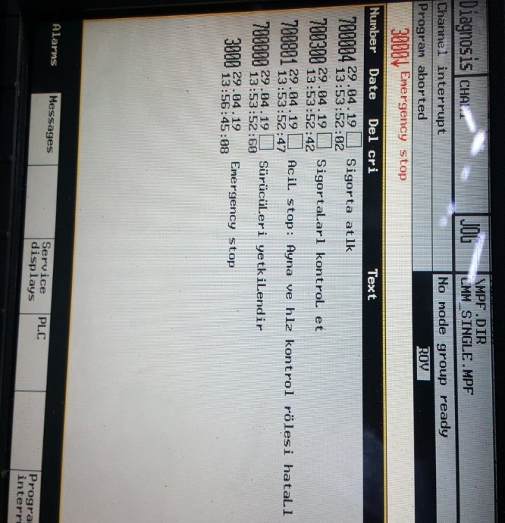
Siemens Sinumerik 840D alarm list (840D/840Di/810D and similar controls), for cnc machinists and maintenance personnel who work on cnc machines with Sinumerik cnc controls.

Siemens Sinumerik Alarms
Sinumerik 840D Alarm List
- 1000 System error %1
- 1001 System error %1
- 1002 System error %1
- 1003 Alarm pointer for this self-clearing alarm %1 is zero
- 1004 Alarm reaction to NCK alarm incorrectly configured
- 1005 Operating system error %1 parameter %2 %3 %4
- 1010 Channel %1 system error %2 action %3
- 1011 Channel %1 %3 %4 system error %2
- 1012 Channel %1 system error %2 %3 %4
- 1013 Channel %1 system error %2
- 1014 Channel %1 system error %2
- 1015 Channel %1 axis %2 system error %3
- 1016 Channel %1 axis %2 system error %3
- 1017 Channel %1 axis %2 system error %3
- 1018 Floating point arithmetic error in channel %1 task %2 station %3 FPU state %4 %4
- 1019 Floating point arithmetic error at address %3 in channel %1 task %2 FPU state %4
- 1030 System error in link module error code %1 error type %2
- 1031 Link module generated an unspecified error %1 NCU %2 %3 %4
- 1100 No valid firmware
- 1160 Assertion failed in %1: %2
- 2000 PLC sign-of-life monitoring
- 2001 PLC has not started up
- 2100 NCK battery warning threshold reached
- 2101 NCK battery alarm
- 2102 NCK battery alarm
- 2110 NCK temperature alarm
- 2120 NCK fan alarm
- 2130 5V/24V encoder or 15V D/A converter under voltage
- 2140 The actual service switch position forces a SRAM to be cleared at the next Power On (general reset active)
- 2190 Hardware plug-in module for communication with the digitizer missing
- 2192 No NCU link module exists, MD %1 reset
- 2193 “Safety Integrated” is not available for link axis %1.
- 2195 Channel %1 axis %2 high-speed punching/nibbling not possible via link
- 2196 Link axis active and $MN_MM_SERVO_FIFO_SIZE != %1
- 2900 Reboot is delayed
- 3000 Emergency stop
- 3001 Internal emergency stop
- 4000 Channel %1 machine data %2[%3] has gap in axis assignment
- 4001 Channel %1 axis %2 defined for more than one channel via machine data %3
- 4002 Channel %1 machine data %2[%3] assigns an axis not defined in channel
- 4003 Axis %1 incorrect assignment of master channel in machine data %2
- 4004 Channel %1 machine data %2 axis %3 defined repeatedly as geometry axis
- 4005 Maximum number of axes in channel %1 exceeded. Limit %2
- 4007 Axis %1 incorrect assignment of master NCU in machine data %2
- 4010 Invalid identifier used in machine data %1[%2]
- 4011 Channel %1 invalid identifier used in machine data %2[%3]
- 4012 Invalid identifier used in machine data %1[%2]
- 4013 Invalid NCU link configuration by machine data %1 = %2 , on NCU_1 = %3
- 4014 Axis %1 defined several times in %2
- 4016 Axis %1 already used by NCU %2
- 4017 Axis container %1, location %2 already used by NCU %3
- 4018 Axis container %1, location %2 not used by any channel
- 4019 Axis container %1 advance not allowed with current status of NCU %2
- 4020 Identifier %1 used several times in machine data %2
- 4021 Channel %1 identifier %2 used several times in machine data %3
- 4022 Axis container %3 switch not allowed: ext. zero offset active channel %1 axis %2
- 4023 Axis container %1 switch not allowed, axis container %2 switch active
- 4024 Invalid axis configuration due to missing axis container machine data
- 4025 Axis container %3 switch not allowed: master/slave active channel %1 axis %2
- 4026 Machine data %1[%2], link axis NC%3_AX%4 not used by any channel
- 4027 Notice: MD %1 was also changed for the other axes of axis container %2
- 4028 Notice! The axial MDs of the axes of the axis containers were matched.
- 4029 Notice: the axial MDs in axis container %1 will be matched on the next power-up
- 4030 Channel %1 axis identifier missing in machine data %2[%3]
- 4031 Channel %1 link axis %2 defined for more than one channel in machine data %3
- 4032 Channel %1 wrong identifier for facing axis in %2
- 4033 Notice: NCU link communication still not connected
- 4034 Local link axis %1 is not allowed for different interpolation cycle time = %2/%3
- 4035 Interpolation cycle from NCU%1 = %2 does not match NCU%3 = %4
- 4036 Wrong NCU link configuration by MD %1
- 4040 Channel %1 axis identifier %2 not consistent with machine data %3
- 4045 Channel %1 conflict between machine data %2 and machine data %3
- 4050 NC code identifier %1 cannot be reconfigured to %2
- 4060 Standard machine data loaded
- 4062 Backup data loaded
- 4065 Buffered memory was restored from backup medium (potential loss of data!)
- 4066 Buffered memory of FFS restored from backup medium (potential loss of data!)
- 4070 Normalizing machine data has been altered
- 4073 Compile cycle functions define machine data number %1 several times
- 4075 Machine data %1 (and maybe others) not altered due to missing permission level %2
- 4076 %1 Machine data could not be altered with permission level %2
- 4077 New value %1 of MD %2 not set. Requested %3 bytes too much %4 memory.
- 4080 Incorrect configuration of indexing axis in MD %1
- 4090 Too many errors during power-up
- 4100 System cycle time/scan time divider corrected for digital drive
- 4102 Default values for drive cycle times differ
- 4110 IPO factor increased to %1
- 4111 PLC cycle increased to %1 ms
- 4112 Servo cycle changed to %1 ms
- 4113 Sysclock cycle changed to %1 ms
- 4114 Error in DP cycle of SDB1000
- 4115 Time ratio communication to Ipo changed to %1
- 4150 Channel %1 invalid M function sub program call configured
- 4152 Illegal configuration of the “Block display with absolute values” function
- 4160 Channel %1 invalid M function number configured for spindle switchover
- 4170 Invalid M function number for channel synchronisation assigned
- 4180 Invalid M function number assigned to enable ASUP
- 4181 Channel %1 invalid assignment of an M auxiliary function number
- 4182 Channel %1 invalid M auxiliary function number in %2%3, MD reset
- 4183 Channel %1 M auxiliary function number %2 used several times (%3 and %4)
- 4184 Channel %1 illegally predefined auxiliary function in %2%3, MD reset
- 4185 Channel %1 illegal auxiliary function configured %2 %3 %4
- 4200 Channel %1 geometry axis %2 must not be declared a rotary axis
- 4210 Channel %1 spindle %2 declaration as rotary axis missing
- 4215 Channel %1 spindle %2 declaration as modulo axis missing
- 4220 Channel %1 spindle %2 declared repeatedly
- 4225 Channel %1 axis %2 declaration as rotary axis missing
- 4230 Channel %1 data alteration from external not possible in current channel state
- 4240 Runtime overflow for IPO cycle or position controller cycle, IP %1
- 4250 FastPlcCom functionality not available
- 4252 PLCIO read error: %1
- 4254 PLCIO write error: %1
- 4260 Machine data %1 illegal
- 4270 Machine data %1 assigns not activated NCK input/output byte %2
- 4275 Machine data %1 and %2 both assign the same NCK output byte no. %3 several times
- 4280 Assignment of NCK input/output byte via MD %1[%2] does not match hardware configuration
- 4282 Hardware of external NCK outputs assigned repeatedly
- 4285 Error on terminal block %1, error code %2
- 4290 Local P-bus sign-of-life monitoring
- 4291 Module in local P-bus slot %1 error codes %2 %3 %4 %2 %3 %4
- 4300 Declaration in MD %1 is not allowed for geometry axis/spindle %2.
- 4310 Declaration in MD %1 index %2 is not allowed.
- 4320 Axis %1 function %2 %3 and %4 not allowed
- 4334 Channel %1 The amount of fine correction in parameter %2 of the orientable toolholder %3 is too large
- 4336 Channel %1 orientable toolholder no. %2 for orientation transformation %3 does not exist
- 4338 Channel %1 invalid transformation type ‘%2’ in toolholder %3 for orientation transformer %4
- 4340 Channel %1 block %2 invalid transformation type in transformation no. %3
- 4341 Channel %1 block %2 no data set available for transformation no. %3
- 4342 Channel %1 invalid machine data for general 5-axis transformation error no. %2
- 4343 Channel %1 attempt made to change the machine data of an active transformation.
- 4345 Channel %1 invalid configuration in chained transformation no.%2
- 4346 Channel %1 invalid geoaxis assignment in machine data %2[%3]
- 4347 Channel %1 invalid channel axis assignment in machine data %2[%3]
- 4350 Channel %1 axis identifier %2 machine data %3 not consistent with machine data %4
- 4400 MD alteration will cause reorganisation of buffered memory (loss of data!)
- 4502 Channel %1 anachronism %2(%3) -> %4
- 5000 Communication job not executable %1
- 6000 Memory reorganized using standard machine data
- 6010 Channel %1 data block %2 not or not completely created, error code %3
- 6020 Machine data have been altered – now memory is reorganized
- 6030 Limit of user memory has been adapted
- 6035 Instead of %1 KB the system has only %2 KB of free user memory of type “%3”
- 6100 Error while creating %1, error number %2 %3
- 6401 Channel %1 tool change not possible: Empty location for tool %2 Duplo no. %3 on magazine %4 not available.
- 6402 Channel %1 tool change not possible. Magazine no. %2 not available
- 6403 Channel %1 tool change not possible. Magazine location number %2 on magazine %3 not available.
- 6404 Channel %1 tool change not possible. Tool %2 not available or not usable
- 6405 Channel %1 command %2 has invalid PLC acknowledge parameter %3 – identifier %4
- 6406 Channel %1 PLC acknowledge for command %2 is missing
- 6407 Channel %1 tool %2 cannot be placed in magazine %3 on location %4.Invalid definition of magazine!
- 6410 TO unit %1 tool %2 / Duplo no. %3 has reached its pre warning limit with D = %4
- 6411 Channel %1 tool %2 / Duplo no. %3 has reached its prewarning limit with D = %4
- 6412 TO unit %1 tool %2 / Duplo no. %3 has reached its monitoring limit with D = %4
- 6413 Channel %1 tool %2 / Duplo no. %3 has reached its monitoring limit with D = %4
- 6421 Channel %1 tool move not possible. Empty location for tool %2 Duplo no. %3 on magazine %4 not available.
- 6422 Channel %1 tool move not possible. Magazine no. %2 not available.
- 6423 Channel %1 tool move not possible. Location %2 on magazine %3 not available.
- 6424 Channel %1 tool move not possible. Tool %2 not available/not usable.
- 6425 Channel %1 tool %2 cannot be placed in magazine %3 on location %4. Invalid definition of magazine!
- 6430 Workpiece counter: overflow in table of monitored cutting edges.
- 6431 Function not allowed. Tool management/monitoring is not active.
- 6432 Function not executable. No tool assigned to tool holder/spindle
- 6433 Channel %1 block %2 %3 not available with tool management
- 6434 Channel %1 block %2 NC command SETMTH not allowed because tool holder function not active
- 6441 Writing of $P_USEKT not allowed.
- 6442 Channel %1 function not executable. No tool assigned to desired magazine/magazine location %2.
- 6450 Channel %1 tool change not possible. Invalid magazine location no. %2 in buffer magazine
- 6451 Channel %1 tool change not possible. No buffer magazine defined.
- 6452 Channel %1 tool change not possible. Tool holder/spindle number = %2 not defined.
- 6453 Channel %1 tool change not possible. No assignment between toolholder/spindle no. = %2 and buffer magazine location %3
- 6454 Channel %1 tool change not possible. No distance relation available.
- 6500 NC memory full
- 6510 Too many part programs in the NC memory
- 6520 The value of the machine data %1%2 is too low
- 6530 Too many files in directory
- 6540 Too many directories in the NC memory
- 6550 Too many subdirectories
- 6560 Data format not allowed
- 6570 NC memory full
- 6580 NC memory full
- 6600 NC card memory is full
- 6610 Too many files open on NC card
- 6620 NC card has incorrect format
- 6630 NC card hardware is defective
- 6640 NC card is not inserted
- 6650 Write protection of NC card is active
- 6660 ‘Flash File System’ option is not set
- 6670 NC card read active
- 6671 NC card write active
- 6690 Cycles from NC card cannot be copied to the passive file system.
- 6691 Cycles from the passive file system cannot be saved on the NC card
- 6692 Cycle %1 lost
- 6693 File %1 lost
- 6698 Unknown NC card (%1/%2). Writing not possible.
- 6700 Channel %1 value of the machine data %2%3 is too low
- 7000 Too many compile cycle alarms defined
- 7010 Range of MMC alarm numbers for compile cycles exceeded
- 7020 Compile cycle alarm number has not been defined
- 7100 Compile cycles VDI area: %1 byte for inputs and %2 byte for outputs. Maximum %3 bytes available.
- 7200 Problem with externally linked compile cycle %1 %2
- 7201 Assertion error in %1 line %2
- 7202 Missing option bit for %1: %2
- 8000 Channel %1 option ‘user interrupt programs’ not set
- 8010 Option ‘activation of more than %1 axes’ not set
- 8020 Option ‘activation of more than %1 channels’ not set
- 8021 Option ‘activation of more than %1 mode groups’ not set
- 8022 Option ‘activation of more than %1KB SRAM’ not set
- 8030 Channel %1 block %2 option ‘interpolation of more than 4 axes’ not set
- 8032 Option ‘activation of more than %1 link axes’ not set
- 8034 Option ‘activation of axis containers’ not set
- 8036 Option: it is not allowed to set different IPO cycles or position control cycles with NCU link.
- 8038 Option ‘activation of more than %1 lead link axes’ not set
- 8040 Machine data %1 reset, corresponding option is not set
- 8041 Axis %1: MD %2 reset, corresponding option not sufficient
- 8044 Option for IPO cycle time %1 ms not set
- 8045 Option for selected cycle settings not set
- 8080 %1 options are activated without setting the license key
- 8081 %1 options are activated that are not licensed by the license key
- 8082 The license key was entered three times, Power On required before next try.
- 8098 Invalid combination of options (%1)
- 8100 Channel %1 block %2: function not possible
- 10203 Channel %1 NC start without reference point
- 10207 Channel %1 error when selecting or deselecting the digitize function
- 10208 Channel %1 continue program with NC start
- 10209 Channel %1 internal NC stop after block search
- 10222 Channel %1 inter-channel communication not possible
- 10223 Channel %1: Command %2 is already occupied
- 10225 Channel %1: command denied
- 10299 Channel %1 Auto-Repos function is not enabled
- 10600 Channel %1 block %2 auxiliary function during thread cutting active
- 10601 Channel %1 block %2 zero velocity at block end point during thread cutting
- 10604 Channel %1 block %2 thread lead increase too high
- 10605 Channel %1 block %2 thread lead decrease too high
- 10607 Channel %1 block %2 thread with frame not executable
- 10610 Channel %1 axis %2 not stopped
- 10620 Channel %1 block %3 axis %2 at software limit switch %4
- 10621 Channel %1 axis %2 rests on software limit switch %3
- 10630 Channel %1 block %2 axis %3 at working area limit %4
- 10631 Channel %1 axis %2 rests at working area limit %3
- 10650 Channel %1 axis %2 incorrect gantry machine data, error code %3
- 10651 Channel %1 illegal gantry configuration. Error code %2
- 10652 Channel %1 axis %2 gantry warning threshold exceeded
- 10653 Channel %1 axis %2 gantry error threshold exceeded
- 10654 Channel %1 waiting for synchronization start of gantry group %2
- 10655 Channel %1 synchronization of gantry group %2 in progress
- 10656 Channel %1 axis %2 gantry alarm not yet used
- 10700 Channel %1 block %2 NCK protection zone %3 violated during automatic or MDA mode
- 10701 Channel %1 block %2 channel-specific protection zone %3 violated during automatic or MDA mode
- 10702 Channel %1 NCK protection zone %2 violated during manual mode
- 10703 Channel %1 channel-specific protection zone %2 violated during manual mode
- 10704 Channel %1 block %2 protection zone monitoring is not guaranteed
- 10706 Channel %1 NCK protection zone %2 reached with axis %3 during manual mode
- 10707 Channel %1 channel-specific protection zone %2 reached with axis %3 during manual mode
- 10710 Channel %1 block %2 conflict with centre less grinding
- 10720 Channel %1 block %3 axis %2 software limit switch %4
- 10721 Channel %1 block %3 axis %2 software limit switch %4
- 10730 Channel %1 block %3 axis %2 working area limitation %4
- 10731 Channel %1 block %3 axis %2 working area limitation %4
- 10740 Channel %1 block %2 too many empty blocks in WAB programming
- 10741 Channel %1 block %2 direction reversal with WAB infeed motion
- 10742 Channel %1 block %2 WAB distance invalid or not programmed
- 10743 Channel %1 block %2 WAB programmed several times
- 10744 Channel %1 block %2 no valid WAB direction defined
- 10745 Channel %1 block %2 WAB end position not clear
- 10746 Channel %1 block %2 block search stop for WAB
- 10747 Channel %1 block %2 retraction direction not defined for WAB
- 10748 Channel %1 block %2 illegal retract plane with WAB
- 10750 Channel %1 block %2 tool radius compensation activated without tool number
- 10751 Channel %1 block %2 danger of collision due to tool radius compensation
- 10752 Channel %1 block %2 overflow of local block buffer with tool radius compensation
- 10753 Channel %1 block %2 selection of the tool radius compensation only possible in linear block
- 10754 Channel %1 block %2 deselection of the tool radius compensation only possible in linear block
- 10755 Channel %1 block %2 selection of the tool radius compensation via KONT not possible at the current starting point
- 10756 Channel %1 block %2 deselection of the tool radius compensation via KONT not possible at the programmed end point
- 10757 Channel %1 block %2 changing the compensation plane while tool radius compensation is active not possible
- 10758 Channel %1 block %2 curvature radius with variable compensation value too small
- 10759 Channel %1 block %2 path is parallel to tool orientation
- 10760 Channel %1 block %2 helical axis is not parallel to tool orientation
- 10761 Channel %1 block %2 tool radius compensation for ellipse with more than one revolution not possible
- 10762 Channel %1 block %2 too many empty blocks between two traversing blocks with active tool radius compensation
- 10763 Channel %1 block %2 path component of the block in the compensation plane becomes zero
- 10764 Channel %1 block %2 discontinuous path with active tool radius compensation
- 10765 Channel %1 block %2 3D tool radius compensation not possible
- 10766 Channel %1 illegal change of surface orientation between block %2 and block %3
- 10767 Channel %1 block %2 processing with tilt angle unequal 0 not possible
- 10768 Channel %1 block %2 illegal tool orientation with 3D tool radius compensation
- 10769 Channel %1 block %2 Illegal surface normal vector with 3D tool radius compensation
- 10770 Channel %1 block %2 change of corner type due to change of orientation with active tool radius compensation
- 10771 Channel %1 block %2 overflow of local block buffer due to orientation smoothing
- 10772 Channel %1 block %2 illegal orientation change when activating or deactivating 3D face cutting
- 10773 Channel %1 illegal tool orientation in block %2 at inside corner with block %3
- 10774 Channel %1 illegal tool dimensions with face cutting in block %2
- 10775 Channel %1 illegal tool change with face cutting in block %2
- 10776 Channel %1 block%2 axis %3 must be geometry axis if tool radius compensation is active
- 10777 Channel %1 block %2 tool radius compensation: too many blocks with suppression of compensation
- 10778 Channel %1 block %2 preprocessing stop with active tool radius compensation
- 10779 Channel %1 block %2 preprocessing stop with active tool radius compensation
- 10780 Channel %1 block %2 preprocessing stop with active tool radius compensation
- 10781 Channel %1 block %2 illegal orientation of involute with tool radius compensation
- 10782 Channel %1 block %2 illegal curve type with tool radius compensation
- 10783 Channel %1 block %2 tool radius compensation type requires orientation transformation
- 10784 Channel %1 block %2 illegal tool for tool radius compensation with constraint surface
- 10790 Channel %1 block %2 plane change during linear programming with angles
- 10791 Channel %1 block %2 invalid angle during linear programming
- 10792 Channel %1 block %2 illegal interpolation type during linear programming with angles
- 10793 Channel %1 block %2 second block missing during linear programming with angles
- 10794 Channel %1 block %2 angle specification missing in second block during linear interpolation with angles
- 10795 Channel %1 block %2 end point specification during angle programming contradictory
- 10800 Channel %1 block %3 axis %2 is not a geometry axis
- 10805 Channel %1 block %2 repositioning after switch of geometry axes or transformation
- 10810 Channel %1 block %2 master spindle not defined
- 10820 Channel %1 rotary axis/spindle %2 not defined
- 10860 Channel %1 block %2 feedrate not programmed
- 10861 Channel %1 block %3 velocity of positioning axis %2 is zero
- 10862 Channel %1 block %2 master spindle also used as path axis
- 10870 Channel %1 block %2 facing axis not defined
- 10880 Channel %1 block %2 too many empty blocks between two traversing blocks when inserting chamfers or radii
- 10881 Channel %1 block %2 overflow of local block buffer when inserting chamfers or radii
- 10882 Channel %1 block %2 activation of chamfers or radii (non-modal) without traversing movement in the block
- 10883 Channel %1 block %2 chamfer or fillet has to be reduced
- 10890 Channel %1 block %2 overflow of local block buffer when calculating splines
- 10891 Channel %1 block %2 multiplicity of node is greater than its order
- 10900 Channel %1 block %2 no S value programmed for constant cutting speed
- 10910 Channel %1 block %2 excessive velocity of one path axis
- 10911 Channel %1 block %2 transformation prohibits to traverse the pole
- 10912 Channel %1 block %2 preprocessing and main run might not be synchronized
- 10913 Channel %1 block %2 negative feed profile is ignored
- 10914 Movement not possible while transformation active – in channel %1, block %2
- 10930 Channel %1 block %2 interpolation type not allowed in stock removal contour
- 10931 Channel %1 block %2 incorrect stock removal contour
- 10932 Channel %1 block %2 preparation of contour has been restarted
- 10933 Channel %1 block %2 contour program does not contain enough contour blocks
- 10934 Channel %1 block %2 array for contour segmentation is set too small
- 10940 Channel %1 block %2 curve table %3: delete/overwrite not possible
- 10941 Channel %1 block %2 curve table %3: NC memory full
- 10942 Channel %1 block %2 curve table %3: illegal instruction during definition
- 10943 Channel %1 block %2 curve table %3: direction reversal of lead value in the block not allowed
- 10944 Channel %1 block %2 curve table %3: illegal transformation
- 10945 Channel %1 block %2 curve table %3: illegal coupling of axes
- 10946 Channel %1 block %2 curve table %3: no contour defined
- 10947 Channel %1 block %2 curve table %3: contour not continuous
- 10948 Channel %1 block %2 curve table %3: position jump at end of period
- 10949 Channel %1 block %2 curve table %3: missing master axis motion
- 10950 Channel %1 calculation of arc length function too inaccurate
- 10951 Channel %1 block %2 curve table %3: following value period is zero
- 10955 Channel %1 block %2 curve table %3: missing master axis motion
- 10956 Channel %1 block %2 curve table %3: NC memory limit DRAM reached
- 10960 Channel %1 block %2 COMPCURV/COMPCAD and radius compensation cannot be used simultaneously
- 10961 Channel %1 block %2 maximum cubic polynomials are allowed on active radius compensation.
- 10962 Channel %1 block %2 function %3 not possible with path correction
- 12000 Channel %1 block %2 address %3 programmed repeatedly
- 12010 Channel %1 block %2 address %3 address type programmed too often
- 12020 Channel %1 block %2 illegal address modification
- 12030 Channel %1 block %2 invalid parameter or data type in %3
- 12040 Channel %1 block %2 expression %3 is not of data type ‘AXIS’
- 12050 Channel %1 block %2 DIN address %3 not configured
- 12060 Channel %1 block %2 same G group programmed repeatedly
- 12070 Channel %1 block %2 too many syntax-defining G functions
- 12080 Channel %1 block %2 syntax error in text %3
- 12090 Channel %1 block %2 unexpected parameter %3
- 12100 Channel %1 block %2 number of passes %3 not permissible
- 12110 Channel %1 block %2 block syntax cannot be interpreted
- 12120 Channel %1 block %2 G function not separately programmed
- 12130 Channel %1 block %2 illegal tool orientation
- 12140 Channel %1 block %2 functionality %3 not implemented
- 12150 Channel %1 block %2 operation %3 not compatible with data type
- 12160 Channel %1 block %2 range of values exceeded
- 12170 Channel %1 block %2 identifier %3 defined repeatedly
- 12180 Channel %1 block %2 illegal chaining of operators %3
- 12190 Channel %1 block %2 variable of type ARRAY has too many dimensions
- 12200 Channel %1 block %2 symbol %3 cannot be created
- 12210 Channel %1 block %2 string %3 too long
- 12220 Channel %1 block %2 binary constant %3 in string too long
- 12230 Channel %1 block %2 hexadecimal constant %3 in string too long
- 12240 Channel %1 block %2 tool orientation %3 defined repeatedly
- 12250 Channel %1 block %2 nested macro %3 not possible
- 12260 Channel %1 block %2 too many initialization values specified %3
- 12261 Channel %1 block %2 initialization of %3 not allowed
- 12270 Channel %1 block %2 macro identifier %3 already defined
- 12280 Channel %1 block %2 maximum macro length %3 exceeded
- 12290 Channel %1 block %2 arithmetic variable % 3 not defined
- 12300 Channel %1 block %2 call-by-reference parameter missing on subroutine call %3
- 12310 Channel %1 block %2 axis parameter missing on procedure call %3
- 12320 Channel %1 block %2 parameter %3 is no variable
- 12330 Channel %1 block %2 type of parameter %3 incorrect
- 12340 Channel %1 block %2 number of parameters too high %3
- 12350 Channel %1 block %2 parameter %3 no longer possible
- 12360 Channel %1 block %2 dimension of parameter %3 incorrect
- 12370 Channel %1 block %2 range of values %3 not permissible
- 12380 Channel %1 block %2 maximum memory capacity reached
- 12390 Channel %1 block %2 initialization value %3 cannot be converted
- 12400 Channel %1 block %2 field %3 element does not exist
- 12410 Channel %1 block %2 incorrect index type for %3
- 12420 Channel %1 block %2 identifier %3 too long
- 12430 Channel %1 block %2 specified index is invalid
- 12440 Channel %1 block %2 maximum number of formal arguments exceeded
- 12450 Channel %1 block %2 label defined twice
- 12460 Channel %1 block %2 maximum number of symbols exceeded with %3
- 12470 Channel %1 block %2 G function %3 is unknown
- 12475 Channel %1 block %2 invalid G function number %3 programmed
- 12480 Channel %1 block %2 subroutine %3 already defined
- 12490 Channel %1 block %2 access permission level %3 is not valid
- 12500 Channel %1 block %2 in this module %3 is not possible
- 12510 Channel %1 block %2 too many machine data %3
- 12520 Channel %1 block %2 too many tool parameters %3
- 12530 Channel %1 block %2 invalid index for %3
- 12540 Channel %1 block %2 Block is too long or too complex
- 12550 Channel %1 block %2 name %3 not defined or option not installed
- 12552 Channel %1 block %2 tool/magazine OEM parameter not defined. Option not set.Option not set.
- 12560 Channel %1 block %2 programmed value %3 exceeds allowed limits
- 12570 Channel %1 block %2 too many motion synchronous actions in %3
- 12571 Channel %1 block %2 %3 not permissible for motion synchronous action
- 12572 Channel %1 block %2 %3 only permissible for motion synchronous action
- 12580 Channel %1 block %2 %3 not permissible for assignment in motion synchronous action
- 12581 Channel %1 block %2 invalid read access to %3 while in motion synchronous action
- 12582 Channel %1 block %2 field index %3 incorrect
- 12583 Channel %1 block %2 variable %3 no system variable
- 12584 Channel %1 block %2 variable %3 cannot be read synchronously with motion
- 12585 Channel %1 block %2 variable %3 cannot be changed synchronously with motion
- 12586 Channel %1 block %2 motion synchronous action: type conflict in variable %3
- 12587 Channel %1 block %2 motion synchronous action: operation/function %3 not allowed
- 12588 Channel %1 block %2 motion synchronous action: address %3 not allowed
- 12589 Channel %1 block %2 motion synchronous action: variable %3 not allowed with modal ID
- 12590 Channel %1 block %2 global user data cannot be created
- 12600 Channel %1 block %2 invalid line checksum
- 12610 Channel %1 block %2 accessing single character with call-by-reference parameter not possible %3
- 12620 Channel %1 block %2 accessing this variable as single character not possible
- 12630 Channel %1 block %2 skip ID/label in control structure not allowed
- 12640 Channel %1 block %2 invalid nesting of control structures
- 12641 Channel %1 block %2 maximum nesting depth of control structures exceeded
- 12650 Channel %1 block %2 axis identifier %3 different in channel %4
- 12660 Channel %1 block %2 motion synchronous action: variable %3 reserved for motion synchronous actions and technology cycles
- 12661 Channel %1 block %2 technology cycle %3: no further subprogram call possible
- 12700 Channel %1 block %2 contour definition programming not allowed as modal sub program is active
- 12701 Channel %1 block %2 illegal interpolation type for contour definition active
- 12710 Channel %1 block %2 illegal language element in external language mode
- 12720 Channel %1 block %2 program number for macro call (G65/G66) missing
- 12722 Channel %1 block %2 multiple ISO_2/3 macro or cycle calls in the block
- 12724 Channel %1 block %2 no radius programmed for cylinder interpolation activation/deactivation
- 12726 Channel %1 block %2 illegal plane selection with parallel axes
- 12728 Channel %1 block %2 distance for double turret not set
- 12730 Channel %1 block %2 no valid transformation machine data parametrized
- 12740 Channel %1 block %2 modal macro call %3 not possible
- 14000 Channel %1 block %2 illegal end of file
- 14001 Channel %1 block %2 illegal end of block
- 14009 Channel %1 block %2 illegal program path %3
- 14010 Channel %1 block %2 invalid default parameter in subroutine call
- 14011 Channel %1 block %2 program %3 not existing or will be edited
- 14012 Channel %1 block %2 maximum subroutine level exceeded
- 14013 Channel %1 block %2 number of subroutine passes invalid
- 14014 Channel %1 selected program %3 not available or will be edited
- 14015 Channel %1 block %2 program %3 is not enabled
- 14016 Channel %1 block %2 error when calling the subroutine via M/T function
- 14017 Channel %1 block %2 syntax error when calling the subroutine via M function
- 14020 Channel %1 block %2 wrong value or wrong number of parameters on function or procedure call
- 14021 Channel %1 block %2 wrong value or wrong number of parameters on function or procedure call
- 14025 Channel %1 block %2 motion synchronous action: illegal modal ID
- 14026 Channel %1 block %2 motion synchronous action: invalid polynomial number in the FCTDEF command
- 14030 Channel %1 block %2 combine OSCILL and POSP during oscillation with in feed motion
- 14033 Channel %1 block %2 involute: no end point programmed
- 14034 Channel %1 block %2 involute: angle of rotation too large
- 14035 Channel %1 block %2 involute: start point invalid
- 14036 Channel %1 block %2 involute: end point invalid
- 14037 Channel %1 block %2 involute: radius invalid
- 14038 Channel %1 block %2 involute not definable: end point error
- 14039 Channel %1 block %2 involute: end point programmed several times
- 14040 Channel %1 block %2 error in end point of circle
- 14045 Channel %1 block %2 error in tangential circle programming
- 14048 Channel %1 block %2 wrong number of revolutions in circle programming
- 14050 Channel %1 block %2 nesting depth for arithmetic operations exceeded
- 14051 Channel %1 block %2 arithmetic error in part program
- 14060 Channel %1 block %2 invalid skip level with differential block skip
- 14070 Channel %1 block %2 memory for variables not sufficient for subroutine call
- 14080 Channel %1 block %2 jump destination %3 not found
- 14082 Channel %1 block %2 label %3 program section not found
- 14085 Channel %1 block %2 instruction not allowed
- 14088 Channel %1 block %2 axis %3 doubtful position
- 14090 Channel %1 block %2 illegal D number
- 14091 Channel %1 block %2 illegal function, index %3 %3
- 14092 Channel %1 block %2 axis %3 is wrong axis type
- 14093 Channel %1 block %2 path interval <= 0 with polynominal interpolation
- 14094 Channel %1 block %2 polynominal degree greater than 3 programmed for polynominal interpolation
- 14095 Channel %1 block %2 radius for circle programming too small
- 14096 Channel %1 block %2 illegal type conversion
- 14097 Channel %1 block %2 string cannot be converted to AXIS type
- 14098 Channel %1 block %2 conversion error: no valid number found
- 14099 Channel %1 block %2 result in string concatenation too long
- 14100 Channel %1 block %2 orientation transformation not available
- 14101 Channel %1 block %2 orientation transformation not active
- 14102 Channel %1 block %2 polynominal degree greater than 5 programmed for orientation vector angle
- 14110 Channel %1 block %2 Euler angles and orientation vector components programmed
- 14111 Channel %1 block %2 Euler angles, orientation vector and transformation axes programmed
- 14112 Channel %1 block %2 programmed orientation path not possible
- 14113 Channel %1 block %2 programmed lead angle too large
- 14114 Channel %1 block %2 programmed tilt angle too large
- 14115 Channel %1 block %2 illegal definition of workpiece surface
- 14116 Channel %1 block %2 absolute orientation programmed while ORIPATH is active
- 14117 Channel %1 block %2 no angle or direction of the cone programmed
- 14118 Channel %1 block %2 no end orientation programmed
- 14119 Channel %1 block %2 no intermediate orientation programmed
- 14120 Channel %1 block %2 plane determination for programmed orientation not possible
- 14122 Channel %1 block %2 angle and direction of the cone programmed
- 14123 Channel %1 block %2 nutation angle of the cone too small
- 14124 Channel %1 block %2 start tangent for orientation is zero
- 14125 Channel %1 block %2 programmed rotation is not possible
- 14129 Channel %1 block %2 orientation angles and orientation vector components programmed
- 14130 Channel %1 block %2 too many initialization values given
- 14131 Channel %1 block %2 orientation axes and lead/tilt angles programmed
- 14132 Channel %1 block %2 orientation axes incorrectly configured
- 14133 Channel %1 block %2 G code for orientation definition not allowed
- 14134 Channel %1 block %2 G code for orientation interpolation not allowed
- 14140 Channel %1 block %2 position programming without transformation not allowed
- 14144 Channel %1 block %2 PTP movement not allowed
- 14146 Channel %1 block %2 CP or PTP movement without transformation not allowed
- 14148 Channel %1 illegal reference system for Cartesian manual traverse
- 14150 Channel %1 block %2 illegal tool carrier number programmed or declared (MD)
- 14151 Channel %1 block %2 illegal tool carrier rotation
- 14152 Channel %1 block %2 tool carrier: invalid orientation. Error code: %3
- 14153 Channel %1 block %2 unknown tool carrier type: %3
- 14154 Channel %1 block %2 The amount of fine correction in parameter %3 of the orientable tool holder %4 is too large
- 14155 Channel %1 block %2 invalid base frame definition for tool carrier offset
- 14156 Channel %1 toolholder selection error at reset
- 14157 Channel %1 block %2 illegal interpolation type with MOVT
- 14159 Channel %1 block %2 more than two angles programmed with ROTS or AROTS
- 14160 Channel %1 block %2 tool length selection without geometry axis specification
- 14165 Channel %1 block %2 active T number does not match selected tool
- 14170 Channel %1 block %2 illegal interpolation type with tool length compensation
- 14180 Channel %1 block %2 H number is not defined
- 14185 Channel %1 block %2 D number is not defined
- 14190 Channel %1 block %2 H number with G49
- 14195 Channel %1 block %2 D number with G49
- 14197 Channel %1 block %2 D number and H number programmed simultaneously
- 14198 Channel %1 block %2 illegal change of tool direction with tool offset
- 14199 Channel %1 block %2 illegal plane change for tool with diameter component
- 14200 Channel %1 block %2 negative polar radius
- 14210 Channel %1 block %2 polar angle too large
- 14250 Channel %1 block %2 negative pole radius
- 14260 Channel %1 block %2 pole angle too large
- 14270 Channel %1 block %2 pole programmed incorrectly
- 14280 Channel %1 block %2 polar coordinates programmed incorrectly
- 14290 Channel %1 block %2 poly nominal degree greater than 5 programmed for poly nominal interpolation
- 14300 Channel %1 block %2 overlaid handwheel motion activated incorrectly
- 14310 Handwheel %1 configuration incorrect or inactive
- 14400 Channel %1 block %2 tool radius compensation active at transformation switchover
- 14401 Channel %1 block %2 transformation not available
- 14402 Channel %1 block %2 spline active at transformation change
- 14403 Channel %1 block %2 preprocessing and main run might not be synchronized
- 14404 Channel %1 block %2 illegal parametrization of transformation
- 14410 Channel %1 block %2 spline active at geometry axis changeover
- 14411 Channel %1 block %2 tool radius compensation active at geometry axis changeover
- 14412 Channel %1 block %2 transformation active at geometry axis changeover
- 14413 Channel %1 block %2 fine tool correction: changeover geometry/channel axis not allowed
- 14414 Channel %1 block %2 GEOAX function: incorrect call
- 14415 Channel %1 block %2 tangent control: changeover geometry/channel axis not allowed
- 14420 Channel %1 block %2 index axis %3 frame not allowed
- 14500 Channel %1 block %2 illegal DEF or PROC instruction in the part program
- 14510 Channel %1 block %2 PROC instruction missing on subroutine call
- 14520 Channel %1 block %2 illegal PROC instruction in data definition section
- 14530 Channel %1 block %2 EXTERN and PROC instruction do not correspond
- 14600 Channel %1 block %2 reload buffer %3 cannot be established
- 14601 Channel %1 block %2 reload buffer could not be deleted
- 14602 Channel %1 block %2 timeout during EXTCALL
- 14610 Channel %1 block %2 compensation block not possible
- 14650 Channel %1 block %2 SETINT instruction with invalid ASUP input
- 14660 Channel %1 block %2 SETINT instruction with invalid priority
- 14700 Channel %1 block %2 timeout during command to interpreter
- 14701 Channel %1 block %2 number of available NC blocks reduced by %3
- 14710 Channel %1 block %2 error in initialization sequence in function %3
- 14720 Channel %1 block %2 axes for centerless transformation not available
- 14730 Channel %1 block %2 conflict at activation of centerless transformation
- 14740 Channel %1 block %2 no tool data available for centerless grinding
- 14745 Channel %1 block %2 centerless grinding not active
- 14750 Channel %1 block %2 too many auxiliary functions programmed
- 14751 Channel %1 block %2 resources for motion synchronous actions not sufficient (code: %3)
- 14752 Channel %1 block %2 DELDTG | STOPREOF conflict
- 14753 Channel %1 block %2 motion synchronous actions with illegal interpolation type
- 14754 Channel %1 block %2 motion synchronous actions and wrong feed type
- 14755 Channel %1 block %2 motion synchronous actions without traverse motion
- 14756 Channel %1 block %2 motion synchronous action and wrong value
- 14757 Channel %1 block %2 motion synchronous action and wrong type
- 14758 Channel %1 block %2 programmed value not available
- 14759 Channel %1 block %2 motion synchronous action and wrong axis type
- 14760 Channel %1 block %2 auxiliary function of a group programmed repeatedly
- 14761 Channel %1 block %2 motion synchronous action: DELDTG function not allowed with active tool radius compensation
- 14762 Channel %1 block %2 too many PLC variables programmed
- 14763 Channel %1 block %2 too many link variables programmed
- 14764 NCU link cannot transfer all link variables immediately
- 14765 NCU link cannot transfer all link variables
- 14766 NCU link is heavily loaded, impending memory shortage
- 14767 Machine data matching via NCU link not complete
- 14770 Channel %1 block %2 auxiliary function programmed incorrectly
- 14780 Channel %1 block %2 unreleased option used
- 14790 Channel %1 block %2 axis %3 programmed by PLC
- 14800 Channel %1 block %2 programmed path speed less or equal to zero
- 14810 Channel %1 block %2 negative axis speed programmed for positioning axis %3
- 14811 Channel %1 block %2 incorrect value range for acceleration of axis/spindle %3
- 14812 Channel %1 block %2 SOFTA not available for axis %3
- 14815 Channel %1 block %2 negative thread lead change programmed
- 14820 Channel %1 block %2 negative value for maximum spindle speed programmed with constant cutting speed
- 14821 Channel %1 block %2 error in selection or deselection of GWPS
- 14822 Channel %1 block %2 incorrect programming of GWPS
- 14823 Channel %1 block %2 error on selection or deselection of tool monitoring
- 14824 Channel %1 block %2 conflict with GWPS
- 14840 Channel %1 block %2 incorrect value range for constant cutting speed
- 14900 Channel %1 block %2 center point and end point programmed simultaneously
- 14910 Channel %1 block %2 invalid angle of aperture for programmed circle
- 14920 Channel %1 block %2 intermediate point of circle incorrect
- 15000 Channel %1 block %2 channel-sync instruction using illegal mark
- 15010 Channel %1 block %2 program coordination instruction with invalid channel number
- 15020 Channel %1 block %2 CHANDATA instruction cannot be executed. Channel %3 is not active
- 15021 Channel %1 block %2 CHANDATA instruction with invalid channel number
- 15025 CHANDATA(%2): channel is not active. Channel data will be ignored.
- 15030 Channel %1 block %2 different measurement system settings
- 15100 Channel %1 block %2 REORG abort caused by log file overflow
- 15110 Channel %1 block %2 REORG not possible
- 15150 Channel %1 block %2 reload from external aborted
- 15160 Channel %1 block %2 wrong preprocessing configuration
- 15165 Channel %1 block %2 error when translating or interpreting PLC Asup %3
- 15166 Channel %1 user system asup _N_ASUP_SPF not available
- 15170 Channel %1 block %2 program %3 could not be compiled
- 15171 Channel %1 block %2 compiled program %3 older than the relevant subroutine
- 15175 Channel %1 block %2 program %3. Interfaces could not be built
- 15180 Channel %1 block %2 program %3 cannot be executed as INI file
- 15185 Channel %1 %2 errors in INI file
- 15190 Channel %1 block %2 not enough free memory for subroutine call
- 15300 Channel %1 block %2 invalid number-of-passed-blocks during block search
- 15310 Channel %1 block %2 file requested during block search is not available
- 15320 Channel %1 block %2 invalid block search command
- 15330 Channel %1 block %2 invalid block number as search target
- 15340 Channel %1 block %2 invalid label as search target
- 15350 Channel %1 block %2 search target not found
- 15360 Channel %1 illegal target of block search (syntax error)
- 15370 Channel %1 target of block search not found
- 15380 Channel %1 block %2 illegal incremental programming in axis %3
- 15390 Channel %1 block %2 %3 not executed during block search
- 15395 Channel %1 master-slave not executable during block search
- 15400 Channel %1 block %2 selected initial init file does not exist
- 15410 Channel %1 block %2 initialization file contains invalid M function
- 15420 Channel %1 block %2 instruction in current mode not allowed
- 15450 Channel %1 block %2 compiled program cannot be stored
- 15460 Channel %1 block %2 syntax error with modal function
- 15500 Channel %1 block %2 illegal angle of shear
- 15700 Channel %1 block %2 illegal cycle alarm number %3
- 15800 Channel %1 block %2 wrong starting conditions for CONTPRON/CONTDCON
- 15810 Channel %1 block %2 wrong array dimension for CONTPRON/CONTDCON
- 15900 Channel %1 block %2 touch probe not allowed
- 15910 Channel %1 block %2 touch probe not allowed
- 15950 Channel %1 block %2 no traverse motion programmed
- 15960 Channel %1 block %2 no traverse motion programmed
Pages: 1 2 3