
Доброго вечера, камрады и гости.
Прошу оказать содействие в ремонте токарного станка САК50135di с ЧПУ Fanuc0i (TF думаю).
Вводные данные такие дали:
Два месяца назад на станке высветилась авар.ошибка sp1241. Консультанты сказали что вышел из строя анал.цифр.преобразователь. В Китае с завода-производителя станка прислали новую «материнскую плату А20В-8200-0545/02А». После установки новой платы система запросила дополнительные настройки. Прислали видео из Китая, все просто, по времени – 2 минуты. Оказалось, что отсутствует файл PMC. Файл нашли на стороне с такого же станка. Достать родные файлы из архива мы не можем. В данный момент система ЧПУ работает, но на экране две ошибки. Снять их не можем.
Очень хочется бэкап, если у кого стоит такое чудо китайской промышленности, поделитесь плиз.
Мои мысли:
1. SV0466 (Z) КОМБИН. ЭЛЕКТРОДВИГ/УСИЛИТ — первый вариант предполагаю неверная настройка 2165, 2020 (или какой там ID двигла).
2. SP1241 (S) ОШИБКА АЦ. ПРЕОБРАЗ — я так предполагаю что это аналоговый шпиндель или всё таки последовательный раз такая ошибка идентифицируется? Просто обычно в названии когда есть CAK то почти всегда 85% это аналоговый шпиндель с китайским нано-частотником.
3. Зачем надо было менять майн плату, я пока не понимаю?
PS: Ехать с пустой головой не хочется, да и не камбечил я как Вы все настройки станков с 0… К чему готовится и какие варианты побороть китайское чудо. Пока даже незнаю что запросить — хотя бы параметры бы знать по двиглам осевым и шпинделю либо пару фоток приводов прикладывали, ужасно когда такое пишут и говорят приезжайте и делайте))) Что-то прям смущается меня sp1241…
Fanuc analog spindle output often has SP1241 alarms. The note in the official manual is: the D/A converter for analog spindle is abnormal. The analog spindle interface is on the FANUC system motherboard, and the OID system is as shown below:

Interface JA40 is an analog spindle output and high-speed jump output interface.

Figure SVC signal is an analog voltage output signal (0-10V), and the dashed SHIELD is a shielded line to prevent interference.
Failure case one:
Trouble phenomenon: SP1241 alarms often appear during the system debugging;
Solution: Observing the electrical cabinet, it is found that SP1241 alarm is prone to occur when the solenoid valve is closed, and the three-phase power supply is not equipped with an arc extinguisher. It is suspected that it will produce electromagnetic interference during operation, which causes the system to mistakenly think that the analog voltage is abnormal and generate SP1241 alarm. Disconnect it (AC contactor) to make the system run. After the machine tool has been working for half a day, no SP1241 alarm occurs. The three-phase arc extinguisher is added to the AC contactor, and the system runs for half a day without SP1241 alarm.
Question keywords: arc extinguishing, interference;
Remarks: The user has not responded and this alarm reappears;
Principle analysis: The working principle of the arc extinguisher is to make it change smoothly when encountering a large current, so as to avoid interference and protect electronic components;


Failure case two:
Trouble phenomenon: SP1241 alarm occasionally occurs during the use of the system: mainly occurs during the simulation of spindle speed changes;
Solution: After adjusting the inverter’s PWM from 15K to 1K, the alarm will be eliminated;
Question keywords: PWM (inverter carrier frequency);
Remarks: After a telephone return visit: the frequency of the alarm is low before adjusting the inverter’s PWM parameters: it occurs once in several days; after adjusting the inverter’s PWM parameters, the alarm phenomenon still exists, but the frequency is very low;
Principle analysis: The inverter controls the motor acceleration and deceleration accuracy through PWM. The greater the value, the greater the control accuracy, and the greater the impact on the 5 and 7 pins of JA40 when the spindle speed changes — the analysis is problematic (should be: The higher the frequency, the higher the frequency of the interference source, the more susceptible to interference).
Failure case three:
Trouble phenomenon: SP1241 alarms often appear during the use of the system: basically every time it is turned on;
Solution: Observe the electric cabinet and find that the analog voltage output cable is hung on the electric cabinet transformer, and connect to the inverter through the terminal block;
Solution: Use shielded wire to connect JA40 pin 5/7 directly to the inverter (without passing through the terminal block), and keep a certain distance from the transformer;
Question keywords: transformer, transfer terminal block, interference;
Remarks: The user has used it continuously for nearly 2 weeks and the alarm did not appear again;
Principle analysis: A. As we all know, the transformer is used for voltage conversion by coil induction, so the transformer is a huge source of interference. Any cable close to the transformer will be induced to get electricity; and the line drawn from the 5th and 7th pins of JA40 Cables that are too close to the transformer will be energized and cause system alarms; B. The middle terminal block will introduce interference from many other circuits (when dealing with the frequent damage of the JA6 port of the laser analog interface board in Jinan Jiemai factory, it can be clearly found by using the oscilloscope The transfer terminal block introduces a lot of interference), which should also be avoided;
Failure case four:
Trouble phenomenon: SP1241 alarms often occur during the system use: the frequency of occurrence is not fixed: sometimes once a day, sometimes once a week; the occurrence time is not fixed, sometimes during the day, sometimes at night, not during the spindle acceleration and deceleration;
Solution: Observe the electrical cabinet and find that the transformer has a greater impact on the overall electrical cabinet;
Solution: i. Use ordinary shielded wires to connect the 5th and 7th pins of JA40 (Wuhan Office Zhao Gang changed to twisted pair and the interference increased and frequent alarms), and added 3 arc extinguishing items to the three inputs of the inverter and the head frame input Move the transformer away from the system (the original position is directly below the system, and the new position is about 70cm away from the system);
Question keywords: transformer, interference;
Failure case five:
Trouble phenomenon: SP1241 alarms often appear during the use of the system: the frequency of occurrence is about 3-4 times a day: sometimes it is 8 or 9 in the morning, sometimes 3 or 4 in the morning; when the alarm occurs, it is during the tool change process of the turret Or the moment the tool is changed;
Solution: Observing the electrical cabinet and discovering that: except for the 220V single-phase AC coil of the turret, there is no arc extinguisher installed, the other three and single-phase contactors have been installed with arc extinguishers when they leave the factory in Yunnan CY;
Solution: add 220V single-phase AC coil corresponding to the turret (forward and reverse)
Failure case six:
Fault phenomenon: SP1241 alarm occurs as soon as the system is powered on during the debugging process;
Solution: power on the system alone, no SP1241 alarm; power on together with Mitsubishi servo drive, immediately SP1241 alarm; turn off Mitsubishi servo starter, power on other parts of the electrical cabinet, no SP1241 alarm;
Problem keywords: interference;
Remarks: On March 28, an oscilloscope was used to confirm that its fluctuation range exceeded plus or minus 20V;
Principle analysis: It is related to the internal structure of the Mitsubishi drive. Because there is no special equipment such as oscilloscope on site, it is impossible to accurately determine the degree of interference (later confirmed that the interference amplitude is above 40V), but it has been confirmed to be related to the Mitsubishi servo drive.
Failure case seven:
Trouble phenomenon: SP1241 alarm occurs as soon as the system is turned on during the debugging process;
Solution: After contacting the maintenance department for confirmation, the system was tested and it was a hardware failure. After replacing the system motherboard, the alarm was eliminated.
Problem keywords: hardware failure;
Note: A bad system motherboard may also cause this fault.
Summary: FANUC analog spindle SP1241 alarms, either the system motherboard is broken, or it is caused by external interference.
In FANUC 0iC system, some are serial spindles (driving the spindle drives produced by FANUC) and some are analog spindles. How to distinguish it from the main board?

The picture above is an OIC motherboard. There is a square chip in the lower left corner. If soldered, it has an analog spindle. If it is not soldered, it is a serial spindle motherboard.
На фоне вышеозвученных на 98-ми страницах проблем (хорошая смена была, детали «долгие», всю ночь за компом просидел, вас читал, много интересного узнал, всем спасибо) даже как-то стыдно стало со своими детскими вопросами сюда влезать… Но вот честно, уже два месяца не могу ответ найти, вдруг здесь помогут.
Простейшая задачка… Fanuc-0i-MF — как в управляйке тактично узнать номер инструмента, стоящего в шпинделе? #4120 по понятным причинам (T1M6; T2; — и «усё») не подходит, сейчас юзаю глобальную переменную (дописал в «M6»), но как-то мне самому это решение «черезодноместным» кажется. Есть возможность программно изъять конкретную цифирь из D0000, или, может, есть какая-то необъявленная в жёлтых книжках переменная, где он (номер) всё-таки лежит?
Второй вопрос. Наконец-то дошли руки до ПО от Renishaw. Затыки начались с ходу… Гуру, объясните, пожалуйста, смысл следующей подпрограммы:
» G53; #116=#5043-#5003; »
В каких случаях #116 не будет равна нулю? Из жёлтой книжки на русском — не понял, но даже и из книжки на английском понятнее не стало.
Третий… Станок — четырёхосевой вертикальный фрезер (тупо поворотная башка на столе), прибыл на контору в апреле. Щупалка и ПО к ней были в комплекте, НО… ребята сразу же скачали соответствующее мобильное приложение, и вот совсем недавно один любознательный тип отловил один факт — есть у них в приложении цикл выставления угла в 4-й оси (втыкаешь в патрон круглую деталь, которая заканчивается какой-то плоской фигней, и можно померять, насколько криво относительно плоскости XY эта фигня стоит), но у нас на станке этого цикла нет. Если вдруг кто сталкивался с хотя бы похожей ситуацией — кому вообще писать по этому поводу — продавцу станка или британцам, и предоставят ли этот цикл бесплатно?
Изменено 25.10.2020 08:26 пользователем Holodov
Below is a list of FANUC servo amplifier alarms and faults with a short description briefly describing the source of each error code. Some point to the source of the problem itself, others point to the problem and do not identify the failing/malfunctioning component.
Servo Amplifiers We Service
- FANUC Alpha, Alpha i series & Alpha is series
- FANUC AC Digital and Analog
- FANUC AC Serial Interface
- FANUC AC Series i & S
Tri Star CNC Services can provide you with more information on the meaning of your alarms. We will provide a fault diagnosis and a dependable 1-year warranty if you require FANUC servo amplifier repairs — or a new FANUC servo amplifier module or FANUC DC servo unit.
| Alarm Code | Description |
|---|---|
|
-(dash) |
Amplifier is not ready |
|
Blinking «-« |
(a) Disconnect the feedback cable (JF*) from the Servo Amplifier, and then switch on the power. (b) Disconnect the feedback cable (JF*) from the Pulsecoder, and then switch on the power. (Keep |
|
0 |
Amplifier is ready (normal operating state) |
|
01, 1 |
DC voltage of the main circuit power supply is abnormally high. Internal cooling circuit faulty Overcurrent flowed into the input of the main circuit. Input supply voltage imbalance, IGBT defective. (PSM-15 to PSM-55) The battery voltage of the absolute pulse coder is low. (warning) The main circuit power module (IPM) has detected an overload, overcurrent, or control supply voltage decrease, overcurrent, or control supply voltage decrease. Internal cooling circuit failure, Overload, Input supply voltage imbalance, IPM failure, or control supply voltage decrease of the power module. |
|
02, 2 |
Internal cooling circuit faulty. Inverter: control power supply undervoltage The battery voltage of the absolute pulse coder is low. |
|
2 (dot) |
+5 VDC of the control circuit power supply is abnormally low. |
|
03, 3 |
DC voltage of the main circuit power supply is abnormally low or the circuit breaker is tripped. The motor has overheated (OHAL). The temperature of the heat sink has risen. |
|
04, 4 |
DC voltage (DC link) has dropped Regenerative discharge energy is too high. Servo motor has overheated (estimated value). |
|
05, 5 |
Average regenerative discharge energy is too high (too frequent acceleration/deceleration) Inverter: DC link undervoltage The input power supply is abnormal (open phase) or the main circuit capacitor was not recharged within the specified time. |
|
5, S |
A communication error for the serial pulse coder was detected. |
|
5 (dot) |
Excessive regenerative discharge alarm. |
|
06, 6 |
Inverter: Overheat |
|
6 (dot) |
Inverter: Overheat |
|
07, 7 |
MCC is faulty. Relay contacts for the dynamic brake is faulty. The DC link voltage is abnormally high. |
|
08, 8 |
Abnormal current alarm (L axis) The offset of the current detection circuit of the main circuit DC link is excessive. The regenerative discharge unit is heated. |
|
8. (dot) |
Inverter: IPM alarm (L axis) |
|
09, 9 |
Abnormal current alarm (M axis) Reference position setting cannot be executed correctly. |
|
9. (dot) |
Inverter: IPM alarm (M axis) |
|
11 |
When the absolute pulse coder is used, the motor has not yet rotated through more than one turn after the first power–up. |
|
16 |
The main circuit power supply has an open phase. |
|
17 |
The DC link voltage is abnormally high. |
|
18 |
An error occurred in internal parameter data transfer processing. |
|
26 |
The frequency of the main circuit input power supply is abnormal. |
|
36 |
The input power supply of the main circuit has an imbalance. |
|
46 |
When the magnetic contactor is turned on, the phase sequence of the power supply cannot be determined. |
|
A |
A parameter has been specified incorrectly. Abnormal current alarm (N axis) External cooling circuit faulty. |
|
A. (dot) |
Inverter: IPM alarm (N axis) |
|
A0 |
ROM is faulty. |
|
A1 |
RAM is faulty |
|
A2 |
A software is not operating normally. |
|
b |
Abnormal current alarm (L axis) Abnormally high current in the L–and M–axis motors DC link current alarm (L axis) |
|
b. (dot) |
IPM alarm for L–and M–axis axes. |
|
BRK |
Breaker has tripped |
|
c |
An overcurrent alarm or IPM alarm DC link current alarm (M axis) |
|
C |
Faulty cooling circuit |
|
d |
Abnormal current alarm (N axis) DC link current alarm N axis) |
|
DC |
Discharge alarm |
|
DCAL |
The regenerative discharge circuit may be faulty |
|
E |
An error was detected in the RAM write/read test at power–up. The input power supply is abnormal (open phase). |
|
F |
External cooling circuit faulty |
|
H |
The temperature of the regenerative resistor has arisen abnormally. (PSMR) |
|
HCAL L/M |
High current flow the the main circuit of that axis has occurred |
|
HCL |
High current alarm L axis |
|
HCM |
High current alarm M axis |
|
HV |
High voltage alarm |
|
HVAL L/M |
DC voltage of the power curcuit for that axis is high |
|
J |
The regenerative discharge unit has overheated |
|
L |
FSSB communication error |
|
LV |
Low voltage alarm |
|
LVAL |
The circuit voltage is unusually low |
|
No LED |
200-V control power (CX1A) is not supplied. Alternatively, the 24-VDC power is short-circuited. |
|
OH |
Overheat alarm |
|
OVC L/M |
Current exceeding the preset value has continued longer than normal. |
|
P |
Communication error between amplifier and module DC link low voltage alarm |
|
TGLS L/M |
Feedback and velocity command mismatch |
|
U |
A parameter that requires power–down has been specified. FSSB communication error |
|
u |
A first to third reference position return cannot be executed because the reference position has not yet been established. |
|
Y |
DC link overvoltage alarm |
contact tri star cnc for repairs Back to Top
| Alarm Code | Message | Description |
|---|---|---|
|
400 |
SERVO ALARM: n–TH AXIS OVERLOAD |
The n–th axis (axis 1–8) overload signal is on. Refer to diagnostic display No. 201, 720 or 721 for details. |
|
401 |
SERVO ALARM: n–TH AXIS VRDY OFF |
The n–th axis (axis 1–8) servo amplifier READY signal (DRDY) went off. |
|
402 |
SERVO ALARM 3, 4TH AXIS OVERLOAD |
3-axis, 4-axis overload signal is on. Refer to diagnostic display 722 or 723 for details. |
|
404 |
SERVO ALARM: n–TH AXIS VRDY ON |
Even though the n–th axis (axis 1–8) READY signal (MCON) went off, the servo amplifier READY signal (DRDY) is still on. Or, when the power was turned on, DRDY went on even though MCON was off. Check that the servo interface module and servo amp are connected. |
|
405 |
SERVO ALARM: (ZERO POINT RETURN FAULT) |
Position control system fault. Due to an NC or servo system fault in the reference position return, there is the possibility that reference position return could not be executed correctly. Try again from the manual reference position return. |
|
407 |
SERVO ALARM: EXCESS ERROR |
The difference in synchronous axis position deviation exceeded the set value. |
|
409 |
SERVO ALARM: n AXIS TORQUE ALM |
Abnormal servo motor load has been detected. Alternatively, abnormal spindle motor load has been detected in Cs mode. |
|
410 |
SERVO ALARM: n–TH AXIS – EXCESS ERROR |
The position deviation value when the n–th axis (axis 1–8) stops is larger than the set value. |
|
411 |
SERVO ALARM: n–TH AXIS – EXCESS ERROR |
The position deviation value when the n–th axis (axis 1–8) moves is larger than the set value. |
|
413 |
SERVO ALARM: n–th AXIS – LSI OVERFLOW |
The contents of the error register for the n–th axis (axis 1–8) exceeded 231 power. This error usually occurs as the result of an improperly set parameters. |
|
414 |
SERVO ALARM: n–TH AXIS – DETECTION RELATED ERROR |
N–th axis (axis 1–8) digital servo system fault. Refer to diagnosis display No. 200 and No.204 for details. Also look at the servo amlifier for alarm code. |
|
415 |
SERVO ALARM: n–TH AXIS – EXCESS SHIFT |
A speed higher than 511875 units/s was attempted to be set in the n–th axis (axis 1–8). This error occurs as the result of improperly set CMR. |
|
416 |
SERVO ALARM: n–TH AXIS – DISCONNECTION |
Position detection system fault in the n–th axis (axis 1–8) pulse coder (disconnection alarm). Refer to diagnosis display No. 201 for details. |
|
417 |
SERVO ALARM: n–TH AXIS – PARAMETER INCORRECT |
This alarm occurs when the n–th axis (axis 1–8) is in one of the conditions listed below. (Digital servo system alarm) 1) The value set in Parameter No. 2020 (motor form) is out of the specified limit. 2) A proper value (111 or –111) is not set in parameter No.2022 (motor revolution direction). 3) Illegal data (a value below 0, etc.) was set in parameter No. 2023 (number of speed feedback pulses per motor revolution). 4) Illegal data (a value below 0, etc.) was set in parameter No. 2024 (number of position feedback pulses per motor revolution). 5) Parameters No. 2084 and No. 2085 (flexible field gear rate) have not been set. 6) A value outside the limit of {1 to the number of control axes} or a non–continuous value (Parameter 1023 (servo axis number) contains a value out of the range from 1 to the number of axes, or an isolated value (for example, 4 not preceded by 3).was set in parameter No. 1023 (servo axisnumber). 7) The amplifier in use does not support the HC alarm avoidance function. If you want to use this amplifier, reset the function bit 2209#4 to 0. If you want to use the HC alarm avoidance function, use an amplifier that supports it. |
|
420 |
SERVO ALARM: n AXIS SYNC TORQUE (M series) |
During simple synchronous control, the difference between the torque commands for the master and slave axes exceeded the value set in parameter No. 2031. |
|
421 |
SERVO ALARM: n AXIS EXCESS ER (D) |
The difference between the errors in the semi–closed loop and closed loop has become excessive during dual position feedback. Check the values of the dual position conversion coefficients in parameters No. 2078 and 2079. |
|
422 |
SERVO ALARM: n AXIS |
In torque control of PMC axis control, a specified allowable speed has been exceeded. |
|
423 |
SERVO ALARM: n AXIS |
In torque control of PMC axis control, the parameter–set allowable cumulative travel distance has been exceeded. |
|
430 |
n AXIS : SV. MOTOR OVERHEAT |
A servo motor overheat occurred. |
|
431 |
n AXIS : CNV. OVERLOAD |
1) PSM: Overheat occurred. 2) β series SVU: Overheat occurred. |
|
432 |
n AXIS : CNV. LOWVOLT CON. |
1) PSM: The control power supply voltage has dropped. 2) PSMR: The control power supply voltage has dropped. 3) β series SVU: The control power supply voltage has dropped |
|
434 |
n AXIS : INV. LOWVOLT CONTROL |
SVM: The control power supply voltage has dropped. |
|
435 |
n AXIS : INV. LOWVOLT DC LINK |
SVM: The DC link voltage has dropped. |
|
436 |
n AXIS : SOFTTHERMAL (OVC) |
The digital servo software detected the soft thermal state (OVC). |
|
437 |
n AXIS : CNV. OVERCURRENT POWER |
PSM: Overcurrent flowed into the input circuit. |
|
438 |
n AXIS : INV. ABNORMAL CURRENT |
1) SVM: The motor current is too high. 2) α series SVU: The motor current is too high. 3) β series SVU: The motor current is too high. |
|
439 |
n AXIS : CNV. OVERVOLT POWER |
1) PSM: The DC link voltage is too high. 2) PSMR: The DC link voltage is too high. 3) α series SVU: The C link voltage is too high. 4) β series SVU: The link voltage is too high. |
|
440 |
n AXIS : CNV. EX DECELERATION POWER |
1) PSMR: The regenerative discharge amount is too large. 2) α series SVU: The regenerative discharge amount is too large. Alternatively, the regenerative discharge circuit is abnormal. |
|
441 |
n AXIS : ABNORMAL CURRENT OFFSET |
The digital servo software detected an abnormality in the motor currentdetection circuit. |
|
442 |
n AXIS : CNV. CHARGE FAILURE |
1) PSM: The spare discharge circuit of the DC link is abnormal. 2) PSMR: The spare discharge circuit of the DC link is abnormal. |
|
443 |
n AXIS : CNV. COOLING FAN FAILURE |
1) PSM: The internal cooling fan failed. 2) PSMR: The internal cooling fan failed. 3) β series SVU: The internal cooling fan failed. |
|
444 |
n AXIS : INV. COOLING FAN FAILURE |
SVM: The internal cooling fan failed. |
|
445 |
n AXIS : SOFT DISCONNECT ALARM |
The digital servo software detected a broken wire in the pulse coder. |
|
446 |
n AXIS : HARD DISCONNECT ALARM |
A broken wire in the built–in pulse coder was detected by hardware. |
|
447 |
n AXIS : HARD DISCONNECT (EXT) |
A broken wire in the separate detector was detected by hardware. |
|
448 |
n AXIS : UNMATCHED FEEDBACK ALARM |
The sign of feedback data from the built–in pulse coder differs from that of feedback data from the separate detector. |
|
449 |
n AXIS : INV. IPM ALARM |
1) SVM: IPM (intelligent power module) detected an alarm. 2) α series SVU: IPM (intelligent power module) detected an alarm. |
|
453 |
n AXIS : SPC SOFT DISCONNECT ALARM |
Software disconnection alarm of the α pulse coder. Turn off the power to the CNC, then remove and insert the pulse coder cable. If this alarm is issued again, replace the pulse coder. |
|
456 |
ILLEGAL CURRENT LOOP |
The current control cycle settings (parameter No. 2004, bit 0 of parameter No. 2003, and bit 0 of parameter No. 2013) are incorrect. Possible problems are as follows. – For the two axes whose servo axis numbers (settings of parameter No. 1023) are an odd number followed by an even number (a pair of axes 1 and 2 or axes 5 and 6, for example), a different current control cycle is set for each of the axes. – The requirements for slaves needed for the set current control cycle, including the number, type, and connection method of them, are not satisfied. |
|
457 |
ILLEGAL HI HRV (250US) |
Use of high–speed HRV is specified although the current control cycle is 200 μs. |
|
458 |
CURRENT LOOP ERROR |
The current control cycle setting does not match the actual current control cycle. |
|
459 |
HI HRV SETTING ERROR |
Of two axes having adjacent servo axis numbers (parameter No. 1023), odd number and even number, high–speed HRV control can be performed for one axis and not for the other. |
|
460 |
n AXIS : FSSB DISCONNECT |
FSSB communication was disconnected suddenly. The possible causes are as follows: 1) The FSSB communication cable was disconnected or broken. 2) The power to the amplifier was turned off suddenly. 3) A low–voltage alarm was issued by the amplifier. |
|
461 |
n AXIS : ILLEGAL AMP INTERFACE |
The axes of the 2–axis amplifier were assigned to the fast type interface. |
|
462 |
n AXIS : SEND CNC DATA FAILED |
Because of an FSSB communication error, a slave could not receive correct data. |
|
463 |
n AXIS : SEND SLAVE DATA FAILED |
Because of an FSSB communication error, a slave could not receive correct data. |
|
464 |
n AXIS : WRITE ID DATA FAILED |
An attempt was made to write maintenance information on the amplifier maintenance screen, but it failed. |
|
465 |
n AXIS : READ ID DATA FAILED |
At power–up, amplifier initial ID information could not be read. |
|
466 |
n AXIS : MOTOR/AMP COMBINATION |
The maximum current rating for the amplifier does not match that for the motor. |
|
467 |
n AXIS : ILLEGAL SETTING OF AXIS |
The servo function for the following has not been enabled when an axis occupying a single DSP (corresponding to two ordinary axes) is specified on the axis setting screen. 1. Learning control (bit 5 of parameter No. 2008 = 1) 2. High–speed current loop (bit 0 of parameter No. 2004 = 1) 3. High–speed interface axis (bit 4 of parameter No. 2005 = 1) |
|
468 |
HI HRV SETTING ERROR(AMP) |
Use of high–speed HRV is specified for a controlled axis of an amplifier which does not support high–speed HRV. |
contact tri star cnc for repairs Back to Top
| Alarm Code | Message | Description |
|---|---|---|
|
600 |
n AXIS: INV. DC LINK OVER CURRENT |
DC link current is too large. |
|
601 |
n AXIS: INV. RADIATOR FAN FAILURE |
The external dissipator cooling fan failed. |
|
602 |
n AXIS: INV. OVERHEAT |
The servo amplifier was overheated. |
|
603 |
n AXIS: INV. IPM ALARM(OH) |
The IPM (intelligent power module) detected an overheat alarm. |
|
604 |
n AXIS: AMP. COMMUNICATION ERROR |
Communication between the SVM and the PSM failed. |
|
605 |
n AXIS: CNV. EX. DISCHARGE POWER |
PSMR: Regenerative power is too large. |
|
606 |
n AXIS: CNV. RADIATOR FAN FAILURE |
PSM: The external dissipator cooling fan failed. PSMR: The external dissipator cooling fan failed. |
|
607 |
n AXIS: CNV. SINGLE PHASE FAILURE |
PSM: Input voltage is in the open–phase condition. PSMR: Input voltage is in the open–phase condition. |
contact tri star cnc for repairs Back to Top
| Alarm Code | Description |
|---|---|
|
SV0027 or 027 |
Invalid digital servo parameter setting |
|
SV0361 or 361 |
Pulsecoder phase error (built-in) |
|
SV0364 or 364 |
Soft phase alarm (built-in) |
|
SV0365 or 365 |
LED error (built-in) |
|
SV0366 or 366 |
Pulse error (built-in) |
|
SV0367 or 367 |
Count error (built-in) |
|
SV0368 or 368 |
Serial data error (built-in) |
|
SV0369 or 369 |
Data transfer error (built-in) |
|
SV0380 or 380 |
LED error (separate) |
|
SV0381 or 381 |
Pulsecoder phase error (separate) |
|
SV0382 or 382 |
Count error (separate) |
|
SV0383 or 383 |
Pulse error (separate) |
|
SV0384 or 384 |
Soft phase alarm (separate) |
|
SV0385 or 385 |
Serial data error (separate) |
|
SV0386 or 386 |
Data transfer error (separate) |
|
SV0387 or 387 |
Sensor error (separate) |
|
SV0417 or 417 |
Invalid parameter |
|
SV0421 or 421 |
Excessive semi-full error |
|
SV0430 or 430 |
Servo motor overheat |
|
SV0432 or 432 |
Converter: control power supply undervoltage |
|
SV0433 or 433 |
Converter: DC link undervoltage |
|
SV0436 or 436 |
Soft thermal (OVC) |
|
SV0438 or 438 |
Inverter: motor current alarm |
|
SV0439 or 439 |
Converter: DC link overvoltage |
|
SV0440 or 440 |
Converter: Excessive deceleration power |
|
SV0441 or 441 |
Current offset error |
|
SV0444 or 444 |
Inverter: internal cooling fan stopped or circuit failed |
|
SV0445 or 445 |
Soft disconnection alarm |
|
SV0447 or 447 |
Hard disconnection alarm (separate) |
|
SV0448 or 448 |
Feedback mismatch alarm |
|
SV0449 or 449 |
Inverter: IPM alarm |
|
SV0453 or 453 |
Soft disconnection alarm (α Pulsecoder) |
|
SV0601 or 601 |
Inverter: cooling fan stopped of the radiator |
|
SV0603 or 603 |
Inverter: IPM alarm (OH) |
contact tri star cnc for repairs Back to Top
| Status 1 Spindle Unit | Status 2 Spindle Unit | Description |
|---|---|---|
|
12 |
Not applicable |
IPM alarm |
|
19 |
Not applicable |
Excessive offset of the phase U current detection circuit |
|
20 |
Not applicable |
Excessive offset of the phase V current detection circuit |
|
21 |
Not applicable |
Position sensor polarity setting incorrect |
|
24 |
Not applicable |
Serial transfer data error |
|
27 |
Not applicable |
Position coder disconnected |
|
29 |
Not applicable |
Short-period overload |
|
30 |
Not applicable |
Overcurrent in the converter input circuit |
|
31 |
Not applicable |
Motor lock alarm |
|
32 |
Not applicable |
Serial communication LSI RAM error |
|
33 |
Not applicable |
Converter: DC link precharge failure |
|
34 |
Not applicable |
Parameter data out of the specifiable range |
|
35 |
Not applicable |
Gear ratio parameter error |
|
37 |
Not applicable |
Speed detector parameter error |
|
41 |
Not applicable |
Position coder one-rotation signal detection error |
|
42 |
Not applicable |
Position coder one-rotation signal not detected |
|
47 |
Not applicable |
Position coder signal error |
|
50 |
Not applicable |
Excessive speed command calculation value during spindle synchronization |
|
51 |
Not applicable |
Converter: DC link undervoltage |
|
52 |
Not applicable |
ITP signal error I |
|
53 |
Not applicable |
ITP signal error II |
|
54 |
Not applicable |
Current overload alarm |
|
58 |
Not applicable |
Converter: main circuit overload |
|
73 |
Not applicable |
Motor sensor disconnected |
|
75 |
Not applicable |
CRC test alarm |
|
79 |
Not applicable |
Abnormal initial test operation |
|
81 |
Not applicable |
Motor sensor one-rotation signal detection error |
|
82 |
Not applicable |
Motor sensor one-rotation signal not detected |
|
83 |
Not applicable |
Motor sensor signal error |
|
84 |
Not applicable |
Spindle sensor disconnected |
|
85 |
Not applicable |
Spindle sensor one-rotation signal detection error |
|
86 |
Not applicable |
Spindle sensor one-rotation signal not detected |
|
87 |
Not applicable |
Spindle sensor signal error |
|
b0 |
Not applicable |
Communication error between amplifier and module |
|
b1 |
Not applicable |
Converter: control power supply low voltage |
|
C0, C1, C2 |
Not applicable |
Communication data alarm |
|
4, 04 |
— (dash) |
Input power supply is abnormal (open phase) |
|
11 |
— (dash) |
DC voltage at the DC link is abnormally high |
|
30 |
— (dash) |
The main circuit power module (IPM) has detected an abnormal condition. |
|
33 |
— (dash) |
The main circuit capacitor was not recharged within the specified time |
|
51 |
— (dash) |
In the main circuit, the DC voltage (DC link) has dropped. |
|
58 |
— (dash) |
Temperature of the main circuit heat sink has risen abnormally |
|
59 |
— (dash) |
Internal cooling circuit faulty |
|
b1 |
— (dash) |
Power supply voltage decrease |
contact tri star cnc for repairs Back to Top
cnc-club.ru
Статьи, обзоры, цены на станки и комплектующие.
Ошибки в FANUC Oi-TD
Ошибки в FANUC Oi-TD
Сообщение Костян челябинский » 12 сен 2016, 12:40

Re: Ошибки в FANUC Oi-TD
Сообщение odekolon » 12 сен 2016, 21:57
на самом деле, подозреваю, что крутые специалисты по фанукам , здесь не тусуются.
я к фануку подошел 2 недели назад, поэтому не стоит мои советы рассматривать как окончательные
сначала я бы почитал мануалы хотя бы отсюда
http://www.chipmaker.ru/files/file/10979/
у фануков, буква M в названии системы означает фрезерный а Т — токарный
таким образом, тебе нужны мануалы на FANUC 0i-D
в каждом мануале часто есть ссылки на другие мануалы этой серии. Дальше — гуглить «FANUC — код мануала — pdf»
потом осмотрел бы все вентиляторы, особенно на драйверах и сервах.
подобные сообщения, может генерить также программа электроавтоматики (PMC) — это «сердце» конкретного станка. ее пишет производитель конкретного станка под свое электрооборудование.
На моем станке — программа запаролена. может оно и к лучшему — сломать труднее.
если сообщения генеряться электроавтоматикой, то понять эти сообщения можно только прочитав РЭ на конкретный станок
но китайцы обычно ленятся писать подробно и понятно
в общем гуглить, читать, думать и опять гуглить..
ЗЫ
а может повезет и откликнется владелец такого же станка!

Re: Ошибки в FANUC Oi-TD
Сообщение Lexxa » 13 сен 2016, 15:22
1) проверить вентиляторы. Кроме вентиляторов на сервосистеме есть венттиляторы на самой чпу (это то что с экраном). Гарантированно один из них подклинивает — обычное дело, засирается все пылью. Достаточно продуть и протереть корпус, чтобы кыльчатка не застревала.
2) ошибки типа ошибка привода шпинделя. У фанука привод шпинделя цепляется не по FSSB а по отдельному кабелю. Кабель этот соединяет ЧПУ (то что с экраном) с приводом. Привода подач соединины последовательно оптикой. Частенько проблема в разъемах.
Более детально вы можете найти информацию в руководстве по тех. обслуживанию и в Connection Manual (hardware) на стойку 0i модель D, если не найдете — ищите на С, там практически все то же самое.
Успехов.

Re: Ошибки в FANUC Oi-TD
Сообщение Костян челябинский » 13 сен 2016, 20:59
Источник
cnc-club.ru
Статьи, обзоры, цены на станки и комплектующие.
FANUC ERROR 607, 613 [ РЕШЕНО! подробности в теме]

FANUC ERROR 607, 613 [ РЕШЕНО! подробности в теме]
Сообщение EX854508 » 22 янв 2019, 09:40
Здравствуйте, форумчане!
Несколько раз встречал подобные темы в инете, но решил систематизировать и представить на суд общественности удобноперевариваемый рецепт лечения ошибок 607, 613 для привода FANUC BiSVSP 40/40-15 A06B-6134-H203 в случае, если ошибка связана непосредственно с ним.
В данном конкретном случае используется система ЧПУ Fanuc 0i-TC
Проблема заключается в следующем — при включении станка возникают ошибки подобного рода (Рис. 1):
1001 SPINDLE DRIVER FAULT (A0.1)
100 ЗАПИСЬ ПАРАМЕТРОВ РАЗРЕШЕНА
401 СБОЙ СЕРВО : X ОСЬ VRDY ВЫКЛ
401 СБОЙ СЕРВО : Z ОСЬ VRDY ВЫКЛ
607 X ОСЬ: ОДНОФАЗН СБОЙ КОНВЕРТЕРА
613 X ОСЬ: ОДНОФАЗН СБОЙ КОНВЕРТЕРА
607 Z ОСЬ: ОДНОФАЗН СБОЙ КОНВЕРТЕРА
613 Z ОСЬ: ОДНОФАЗН СБОЙ КОНВЕРТЕРА
9004 ШПНД 1:СБОЙ ВХОД ПРЕДОХР/ПИТАНИЯ
Из всего этого сумбура выделяем следующие ошибки: 607, 613. Проверяем целостность линий питания, клеммных колодок, если таковые есть, элементы силовой части — контакторы, автоматы и прочее — и если все указанное не вызывает сомнений, выдвигаем в главные подозреваемые привод.
Соответственно, до всех активных действий, делаем резервные копии программ и параметров.
Если ничего более не вызывает сомнений, демонтируем привод и снимаем верхнюю крышку корпуса привода.
Как показано на Рис. 2 — проблема видна на лицо: поджаренные SMD резисторы в нижней части платы. Фото с тыльной стороны.
Как правило, сами SMD компоненты наврятли повреждены, что нельзя сказать о дорожках и переходных точках. С каждой из трех фаз дорожка приходит на шесть последовательно соединенных резистора сопротивлением 2,4 кОм каждый, фазы S и T выполнены одинаково, а вот по фазе R два крайних резистора размещены на тыльной части платы; затем крайний резистор каждой фазы — RR6, RS6, RT6 соединен дорожкой с точками, показанными на Рис. 3.
Результирующее сопротивление между фазными клеммными соединениями и конечными точками должно быть около 14,5 кОм.
В случае нарушения целостности дорожек или SMD компонентов — лепим перемычки или меняем оные.
Рис. 4, 5 — восстановленные дорожки.
Собираем, запускаем, устанавливаем нули — и радуемся!
Источник
Ошибка Fanuc DS0300
Ошибка Fanuc DS0300 – села батарейка, что делать?
 В первую очередь не стоит паниковать! Данная ситуация крайне распространена и легко поддаётся “лечению” – главное всё сделать правильно и не торопиться. Для полного понимания процесса просим Вас внимательно изучить нашу статью! Если на станке ДРУГАЯ ОШИБКА (не связанная с батарейкой) и Вы попали на эту страницу случайно, то рекомендуем Вам перейти по ссылке: “Ошибки FANUC. Расшифровка и рекомендации“. Там собрана полезная информация не только по ошибкам, но и по методам их диагностики.
О чём нам сообщает станок?
В первую очередь необходимо прочитать ошибки с экрана станка, которые можно открыть нажатием клавиши MESSAGE. Там могут быть ошибки следующего содержимого на разных языках:
- DS0300 APC ALARM : (X) AXIS NEED ZRN
- DS0300 APC АВ. С : (Y) НЕОБХ. ВОЗВР. В ИСХ. Т
- DS0307 (Z) APC ALARM : BATTERY LOW 1
- DS0307 (X) APC АВ. СООБ : РАЗР. БАТАР. 1
Вариантов отображения может быть значительно больше, в том числе и на китайском! “Кривой” перевод ошибок на русский порождает еще большее количество интерпретаций – это не важно! Если в списке ошибок встречаются слова BATTERY, БАТАРЕЯ, LOW, РАЗРЯЖЕНА, ZRN, ВОЗВРАТ В ИСХОДНУЮ ТОЧКУ и т.д… А также, всё это сопровождается перечислением координат X, Y, Z – значит причина установлена. Это может быть:
- Разрядившаяся батарея Fanuc (игнорирование предупреждающих сообщений)
- Неправильно заменённая батарея Fanuc (например, на выключенном станке)
- Отсоединение провода энкодера от серводвигателя (при ремонтах и техническом обслуживании)
Зачем нужна эта батарея и где она находится?
Первое и самое важное – Fanuc батарейка позволяет станку не забывать свои координаты при выключенном питании. Вначале, при понижении заряда батареи, станок выдаёт соответствующее предупреждающее сообщение. После первого появления сообщения о низком заряде батареи необходимо как можно скорее её заменить. Вы можете приобрести её у нас, написав нам по форме обратной связи или позвонив по телефону +7 (495) 211-51-66. Заменять батарею необходимо ТОЛЬКО НА ВКЛЮЧЕННОМ СТАНКЕ! Если сообщение было проигнорировано и батарею вовремя не заменили, то в последствии “слетает” машинный ноль станка и потребуется его повторная привязка, требующая ОСТОРОЖНОСТИ!
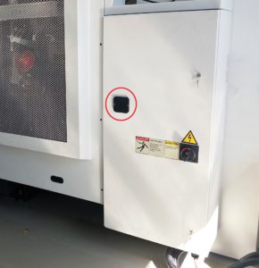 Батарейку необходимо искать внутри электрошкафа станка, на жёлтом блоке Fanuc. Обычно она располагается в коробочке, подвешенной на этот блок управления приводами. Батарейка соединена с блоком при помощи провода с разъёмом. Иногда, например на станках Takisawa, батарейку выносят снаружи электрошкафа и заменяют её на обычные батарейки высокой ёмкости типа D. Их легко купить в любом магазине, а также Вам нет необходимости вызывать электрика для осуществления работ внутри электрошкафа. Такие батарейки могут эксплуатироваться до 5-ти лет, в то время как стандартную батарейку Fanuc необходимо менять 1 раз в год.
На что следует обратить особое внимание?
ВАЖНО. Во избежание серьёзных поломок оборудования рекомендуется визуально контролировать перемещаемые элементы станка на соударение. Для этого требуется снять защитные кожуха перепривязываемых осей. Отметку максимально возможного хода подвижного элемента можно определить по старым масляным следам на направляющих и гайке ШВП. Неправильная привязка осей относительно исходного нуля (с погрешностью более 5мм) может привести к вылету стола станка за свои механические пределы, так как при смещении машинного нуля поле допустимого перемещения смещается вместе с ним! После перепривязки осей ОБЯЗАТЕЛЬНО проверяйте максимальный ход по осям на маленьких скоростях.
Какая последовательность действий?
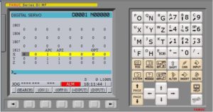
1. Переходим к параметру 1815 (MDI → SYSTEM → 1815 → SEARCH) – это параметр установки машинного нуля станка по координатам. На рисунке изображено исходное состояние параметра 1815. Если привязка машинных нулей “слетела”, то у Вас в столбце APZ будут стоять нули и это не должно Вас смущать.
2. Не забываем перед изменением параметров разрешить их редактирование ( MDI → SET/OFS → SETING → PARAMETER WRITE = 1 ). Заморгает ошибка “редактирование параметров разрешено” – это Вас также не должно смущать
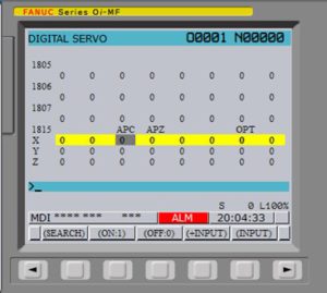
3. Для начала изменения машинных координат необходимо в биты APZ и APC ввести нули, как на картинке и выполнить перезагрузку ЧПУ. Если Вам необходимо привязать только одну ось (например после ремонта или замены двигателя), то выполняйте данную последовательность только для нужной оси, а не для всех одновременно.
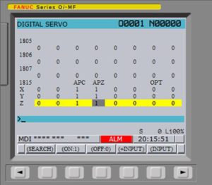
4. Возвращаемся к параметру 1815 и вводим в биты APC единичные значения. Введя значения снова производим перезагрузку ЧПУ.

5. Включив станок перемещаем оси в требуемое нам нулевое положение машинной системы координат (как определить точку машинных координат подробно изложено в следующем разделе). Перемещение станка осуществляется в режиме JOG при этом не рекомендуется использовать ускоренную подачу, так как в данном режиме ход осей не ограничен! Установив оси станка в нужное положение вводим единички в биты APZ и последний раз перезагружаем ЧПУ.
6. Все ошибки с экрана должны исчезнуть, но не спешите радоваться! Ещё нужно проверить правильность проделанных Вами действий! Для этого ознакомьтесь со следующим разделом статьи.
ВНИМАНИЕ. Изменение машинного нуля не приведёт к изменению параметров 1320 и 1321 (они отвечают за ограничения рабочей зоны станка и лимиты перемещений). Поэтому не забудьте их проверить и отредактировать при необходимости.
Как определить нулевое положение машинных координат?
Перед перепривязкой машинной системы координат (МСК) необходимо определить место, где будет находиться новый ноль станка. Для этого начнём с начала. Аксиомой является то, что привязать ноль МСК можно абсолютно в любое место. Нас ограничивают только геометрические параметры станка. Для простоты мы будем привязывать МСК в её предыдущее положение.
Исходными данными для определения этой точки будут значения, установленные в параметрах 1320 и 1321. Эти параметры определяли координаты, за которые станку нельзя было перемещаться. Своего рода программные концевики. При подходе стола к этим координатам ЧПУ останавливает сервопривод, что предохраняет станок от повреждения. Картинка и рисунок ниже помогут Вам понять, за что отвечают значения установленные в параметрах 1320 и 1321.
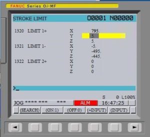
Взяв эти параметры можно рассчитать примерное положение МСК до проведения работ. При этом нужно понимать, что рабочее поле станка может отличаться от размера стола. На картинке рабочее поле станка показано красным прямоугольником. Центр прямоугольника будет соответствовать центру стола. Для большей точности можно нарисовать рабочее поле прямо на столе (маркером) и установить в шпиндель инструмент с острым кончиком (сверло). Кончик сверла необходимо подвести к точке найденного и отмеченного машинного нуля по осям X и Y, а ось Z поднять на максимальную высоту (разумеется не до столкновения гайки ШВП с опорой винта). Максимальную высоту имеет смысл проконтролировать по следам на направляющих.

Корректировка Z координаты смены инструмента.
Невозможно привязать машинный ноль строго в значение, где он был раньше. Поэтому точка смены инструмента также может сместиться! Смещение более 0.2 мм уже может стать причиной серьёзной аварии, поэтому после перепривязки машинного нуля по оси Z обязательно нужно перепроверить координату смены инструмента (параметр 1240)
Определяется необходимое значение в ручном режиме, путём подвода шпинделя в необходимою позицию по оси Z. Ни в коем случае нельзя менять инструмент в автоматическом режиме, до проверки правильности установленной координаты. На картинке показана правильная позиция смены инструмента, расстояние Т зависит от типоразмера конуса патрона.
Установив инструмент в нужную позицию считайте новые машинные координаты смены инструмента из меню POS. Полученные значения вводятся в параметр 1240.
Источник
Fanuc SOi mate-md
![]()
G. СПИСОК СИГНАЛОВ ТРЕВОГИ
7n51 SPN_n_ : LOW VOLT DC LINK (ШПИНДЕЛЬ _n_ : НИЗКОЕ НАПРЯЖЕНИЕ ЦЕПИ ПОСТОЯННОГО ТОКА)
7n52 SPN_n_ : ITP SIGNAL ABNORMAL I (ШПИНДЕЛЬ _n_ : НЕВЕРНЫЙ СИГНАЛ ITP I)
7n53 SPN_n_ : ITP SIGNAL ABNORMAL I (ШПИНДЕЛЬ _n_ : НЕВЕРНЫЙ СИГНАЛ ITP II)
7n54 SPN_n_ : OVERLOAD CURRENT (ШПИНДЕЛЬ _n_ : ПЕРЕГРУЗКА ПО ТОКУ)
7n73 SPN_n_ : MOTOR SENSOR DISCONNECTED (ШПИНДЕЛЬ _n_ : РАЗРЫВ СОЕДИНЕНИЯ С ДАТЧИКОМ МОТОРА)
7n74 SPN_n_ : CPU TEST ERROR (ШПИНДЕЛЬ _n_ : ОШИБКА ТЕСТИРОВАНИЯ ЦП)
7n75 SPN_n_ : CRC ERROR (ШПИНДЕЛЬ _n_ : ОШИБКА CRC)
7n79 SPN_n_ : INITIAL TEST ERROR (ШПИНДЕЛЬ _n_ : ОШИБКА ПЕРВОНАЧАЛЬНОГО ТЕСТИРОВАНИЯ)
сбой в питании или плохой
Обнаружена неисправность в
интерфейсе ЧУ (прекратился
Обнаружена неисправность в
интерфейсе ЧУ (прекратился
Температура радиатора чрез-
Отсутствует сигнал обратной
При тестировании CRC обна-
79 Замените печатную плату При операции первоначальуправления SVPM. ного тестировании обнару-

G. СПИСОК СИГНАЛОВ ТРЕВОГИ
Не выдается сигнал одного
СИГНАЛ ТРЕВОГИ ДРУГОГО КОНВЕРТОРА)

G. СПИСОК СИГНАЛОВ ТРЕВОГИ
Проверьте состояние входного
1 Проверьте и исправьте па-
2 Замените кабель обратной
Проверьте, имеется ли ошибка
дана ли синхронизация шпи-
2 Если останавливается вен-

G. СПИСОК СИГНАЛОВ ТРЕВОГИ
9011 SPN_n_ : OVERVOLT POW CIRCUIT (ШПИНДЕЛЬ _n_ : ЦЕПЬ ПИТАНИЯ С ПЕРЕНАПРЯЖЕНИЕМ)
9012 SPN_n_ : OVERCURRENT POW CIRCUIT (ШПИНДЕЛЬ _n_ : ЦЕПЬ ПИТАНИЯ С ПЕРЕГРУЗКОЙ ПО ТОКУ)
9018 SPN_n_ : SUMCHECK ERROR PGM DATA (ШПИНДЕЛЬ _n_ : ДАННЫЕ ПРОГРАММЫ С ОШИБКОЙ В КОНТРОЛЬНОЙ СУММЕ)
9019 SPN_n_ : EX OFFSET CURRENT U (ШПИНДЕЛЬ _n_ : ЧРЕЗМЕРНОЕ СМЕЩЕНИЕ ТОКА
9020 SPN_n_ : EX OFFSET CURRENT V (ШПИНДЕЛЬ _n_ : ЧРЕЗМЕРНОЕ СМЕЩЕНИЕ ТОКА V)
9021 SPN_n_ : POS SENSOR POLARITY ERROR (ШПИНДЕЛЬ _n_ : ОШИБКА ПОЛЯРНОСТИ ДАТЧИКА ПОЛОЖЕНИЯ)
9024 SPN_n_ : SERIAL TRANSFER ERROR (ШПИНДЕЛЬ _n_ : ОШИБКА ПОСЛЕДОВАТЕЛЬНОЙ ПЕРЕДАЧИ)
11 Проверьте входное напряОбнаружено перенапряжение питания и изменение в жение на участке цепи
питании во время торможения
мотора. Если напряжение пре-
тока, увеличьте полное соп-
Проверьте и исправьте пара-
24 1 Расположите кабель соедиПитание ЧПУ отключено нения шпинделя с ЧПУ в (обычное отключение пи-
стороне от кабеля питания.

G. СПИСОК СИГНАЛОВ ТРЕВОГИ
Проверьте и откорректируйте
Проверьте и откорректируйте
водством. Если номер параме-
проверьте обозначенный пара-

G. СПИСОК СИГНАЛОВ ТРЕВОГИ
значение изменения положе-
в соответствии с руководст-

G. СПИСОК СИГНАЛОВ ТРЕВОГИ
9050 SPN_n_ : SPNDL CONTROL OVERSPEED (ШПИНДЕЛЬ _n_ : ПРЕВЫШЕНИЕ СКОРОСТИ УПРАВЛЕНИЯ ШПИНДЕЛЕМ)
9051 SPN_n_ : LOW VOLT DC LINK (ШПИНДЕЛЬ _n_ : НИЗКОЕ НАПРЯЖЕНИЕ ЦЕПИ ПОСТОЯННОГО ТОКА)
9052 SPN_n_ : ITP SIGNAL ABNORMAL I (ШПИНДЕЛЬ _n_ : НЕВЕРНЫЙ СИГНАЛ ITP I)
9053 SPN_n_ : ITP SIGNAL ABNORMAL I (ШПИНДЕЛЬ _n_ : НЕВЕРНЫЙ СИГНАЛ ITP II)
9054 SPN_n_ : OVERLOAD — CURRENT (ШПИНДЕЛЬ _n_ : ПЕРЕГРУЗКА ПО ТОКУ)
9058 SPN_n_ : OVERLOAD IN SVPM
9073 SPN_n_ : MOTOR SENSOR DISCONNECTED (ШПИНДЕЛЬ _n_ : РАЗРЫВ СОЕДИНЕНИЯ С ДАТЧИКОМ МОТОРА)
9074 SPN_n_ : CPU TEST ERROR (ШПИНДЕЛЬ _n_ : ОШИБКА ТЕСТИРОВАНИЯ ЦП)
9075 SPN_n_ : CRC ERROR (ШПИНДЕЛЬ _n_ : ОШИБКА CRC)
50 Проверьте, не превышает ли При синхронизации шпинвычисленное значение макс. деля программируемое
Проверьте и отрегулируйте
2 Замените в ЧПУ печатную (прекратился сигнал ITP). плату интерфейса шпинделя.
2 Замените в ЧПУ печатную (прекратился сигнал ITP). плату интерфейса шпинделя.
54 Измените состояние нагрузки. Обнаруженаперегрузкапо току.
Проверьте состояние дейст-
Замените печатную плату уп-
Замените печатную плату уп-

G. СПИСОК СИГНАЛОВ ТРЕВОГИ
9079 SPN_n_ : INITIAL TEST ERROR (ШПИНДЕЛЬ _n_ : ОШИБКА ПЕРВОНАЧАЛЬНОГО ТЕСТИРОВАНИЯ)
9081 SPN_n_ : 1-ROT MOTOR SENSOR ERROR (ШПИНДЕЛЬ _n_ : ОШИБКА ДАТЧИКА 1 ОБОРОТА МОТОРА)
9082 SPN_n_ : NO 1-ROT MOTOR SENSOR (ШПИНДЕЛЬ _n_ : ОТСУТСТВИЕ СИГНАЛА ДАТЧИКА 1 ОБОРОТА МОТОРА)
9083 SPN_n_ : MOTOR SENSOR SIGNAL ERROR (ШПИНДЕЛЬ _n_ : ОШИБКА СИГНАЛА ДАТЧИКА МОТОРА)
79 Замените печатную плату При операции первонауправления SVPM. чального тестировании
81 1 Проверьте и исправьте паНельзя безошибочно обраметр. наружить сигнал одного 2 Замените кабель обратной оборота датчика мотора.
B1 Замените печатную плату упНизкое напряжение питаравления SVPM. ния управления конвер-

G. СПИСОК СИГНАЛОВ ТРЕВОГИ
Коды ошибок (последовательный шпиндель)
SVPM показывает код ошибки в качестве 2 — х значного числа в STATUS1 при горящем желтом светодиоде. Коды ошибки появляются в данных диагностики ЧПУ ном. 712.
Когда горит красный светодиод, SVPM показывает номер сигнала тревоги, создаваемого серийным шпинделем, что означает отличное от того, что означает горящий желтый светодиод.
→ См. “Сигналы тревоги (последовательный шпиндель).”
Обнаружение неисправности и способ
01 Когда не вводится ни *ESP (сигнал Проверьте последовательности *ESP и MRDY. Для аварийного останова; имеется два типа MRDY обратите внимание на установку параметра сигналов: сигнал ввода и сигнал контакта относительно использования сигнала MRDY (бит 0 SVPM (*2)), ни MRDY (сигнал готовности параметра ном. 4001).
станка), вводятся SFR (команда вращения вперед), SRV (команда обратноговращения) или ORCM (команда ориентирования).
Когда установки параметра произведены
Проверьте установки параметров.
так, чтобы не использовать датчик поло-
жения, что означает, что регулирование по
положению не исполняется (биты 3, 2, 1, 0
параметра ном. 4002 = 0, 0, 0, 0), вводится
команда управления контуром Cs. В этом
случае мотор не возбуждается.
Когда установки параметров производятся
Проверьте установки параметров.
так, чтобы не использовать датчик положения, чтоозначает, чторегулирование поположениюневыполняется(биты3, 2, 1, 0 параметра ном. 4002 = 0, 0, 0, 0), вводится команда режима сервосистемы (такого, как жесткое нарезание резьбы или позиционирование шпинделя) или команда управления синхронизацией шпинделя. В этом случае мотор не возбуждается.
05 Если параметр опции не установлен для Проверьте установки параметра для функции функции ориентирования, вводится ORCM ориентирования.
Если функция управления переключением Проверьте сигнал состояния силовой линии (RCH).
вывода не используется, выбрано вращение
с низкой скоростью (RCH = 1).
07 Если вводится команда управления конПроверьте последовательность. туром Cs, SFR (команда вращения вперед)
или SRV (команда обратного вращения) не вводятся.

G. СПИСОК СИГНАЛОВ ТРЕВОГИ
Обнаружение неисправности и способ
08 Если вводится команда управления режиПроверьте последовательность. мом сервосистемы (такого, как жесткое нарезание резьбы или позиционирование
шпинделя), SFR (команда вращения вперед) или SRV (команда обратного вращения) не вводятся.
09 Если вводится команда управления синхПроверьте последовательность. ронизацией шпинделя, SFR (команда
вращения вперед) или SRV (команда обратного вращения) не вводятся.
Если вводится команда управления
Во время выполнения команды управления конту-
контуромCs, задаетсядругой режим(режим
ром Cs не задавайте другой режим. Перед вводом
сервосистемы, управление синхронизацией
другого режима отмените команду управления
шпинделя или ориентирование).
11 Если вводится команда режима сервоВо время выполнения команды режима сервосисистемы (такого, как жесткое нарезание стемынезадавайтедругойрежимоперации. Перед резьбы или позиционирование шпинделя), вводом другого режима отмените режим сервозадается другой режим (управление cсистемы.
контуром Cs, управление синхронизацией шпинделя или ориентирование).
Если вводится команда управления
Во время выполнения команды управления синх-
синхронизацией шпинделя, задается другой
ронизацией шпинделя не задавайте другой режим.
режим (управление контуром Cs, режим
Перед вводом другого режима отмените команду
сервосистемы или ориентирование).
управления синхронизацией шпинделя.
14 SFR (команда вращения вперед) и SRV Введите любую из команд. (команда обратного вращения) вводятся в
17 Установки параметра детектора скорости Проверьте установки параметров. (бит 2, 1 и 0 параметра ном. 4011) недействительны. Детектор скорости не соответствует установкам.
Когда установки параметра произведены
Проверьте установки параметра и сигнал ввода.
так, чтобы не использовать датчик поло-
жения, что означает, что регулирование по
положению не исполняется (биты 3, 2, 1, 0 параметра ном. 4002 = 0, 0, 0, 0), задается ориентирование по шифратору положения.
24 Для непрерывного индексирования при Проверьте INCMD (команда приращения). До ориентировании по шифратору сначала последовательного исполнения команд асболютвыполняется операция приращения (INCMD ного положения сначала должно быть выполнено
= 1), а затем вводится команда абсолютного ориентированиекомандыабсолютногоположения.
29 Установки параметра произведены для Нельзя использовать функцию ориентирования в использования функции ориентирования в кратчайшее время Используйте ориентирование
кратчайшеевремя(бит6 праметраном. 4018 обычным методом. = 0, параметры ном. 4320 — 4323 ( 0).
31 Данная конфигурация аппаратного обесПроверьте модель ЧПУ. печениянепозволяетиспользоватьфункцию
FAD шпинделя. В этом случае мотор не возбуждается.
Источник