Частотный преобразователь Schneider Electric Altivar 31 предназначен для управления приводами в системах вентиляции, автоматизированном оборудовании, станках с ЧПУ.
Модельный ряд Altivar 31 включает в себя универсальные преобразователи частоты (ПЧ) небольшой и средней мощности от 0.18 до 15 кВт.
В преобразователях Altivar 31 имеется шесть дискретных и три аналоговых входа, а также один дискретный/аналоговый и два релейных выхода.
Ниже приводятся основные функции ПЧ Altivar 31:
- защита электродвигателя и внутренних компонентов ПЧ;
- линейные S-, U-образные и конфигурируемые кривые разгона, торможения;
- работа в режиме ручного повышения и понижения скорости вращения двигателя;
- 16 предварительно заданных скоростей;
- ПИ-регулятор с гибкими заданиями;
- двух- и трехпроводное управления запуском и остановом;
- алгоритмы управления тормозом;
- автоматический захват с поиском скорости и повторный пуск;
- конфигурирование логики обработки неисправностей и типов останова;
- сохранение конфигураций в памяти ПЧ.
Руководство по эксплуатации Altivar 31 — скачать
Схема подключения Altivar 31:
Список преобразователей Altivar 31:
ATV31H018M2, ATV31H037M2, ATV31H055M2, ATV31H075M2, ATV31HU11M2, ATV31HU15M2, ATV31HU22M2, ATV31H018M3X, ATV31H037M3X, ATV31H055M3X, ATV31H075M3X, ATV31HU11M3X, ATV31HU15M3X, ATV31HU22M3X, ATV31HU30M3X, ATV31HU40M3X, ATV31HU55M3X, ATV31HU75M3X, ATV31HD11M3X, ATV31HD15M3X, ATV31H037N4, ATV31H055N4, ATV31H075N4, ATV31HU11N4, ATV31HU15N4, ATV31HU22N4, ATV31HU30N4, ATV31HU40N4, ATV31HU55N4, ATV31HU75N4, ATV31HD11N4, ATV31HD15N4, ATV31H075S6X, ATV31HU15S6X, ATV31HU22S6X, ATV31HU40S6X, ATV31HU55S6X, ATV31HU75S6X, ATV31HD11S6X, ATV31HD15S6X, ATV31C018M2, ATV31C037M2, ATV31C055M2, ATV31C075M2, ATV31CU11M2, ATV31CU15M2, ATV31CU22M2, ATV31C037N4, ATV31C055N4, ATV31C075N4, ATV31CU11N4, ATV31CU15N4, ATV31CU22N4, ATV31CU30N4, ATV31CU40N4, ATV31K018M2, ATV31K037M2, ATV31K055M2, ATV31K075M2, ATV31KU11M2, ATV31KU15M2, ATV31KU22M2, ATV31K037N4, ATV31K055N4, ATV31K075N4, ATV31KU11N4, ATV31KU15N4, ATV31KU22N4, ATV31KU30N4, ATV31KU40N4, ATV31KU55N4, ATV31KU75N4, ATV31KD11N4, ATV31KD15N4
Коды ошибок Altivar 31:
Ошибка AI2F (error AI2F) – отсутствует сигнал на аналоговом входе AI2;
Ошибка AnF (error AnF) – скорость, измеренная энкодером не совпадает с заданной;
Ошибка bOF (error bOF) – перегрузка тормозного резистора;
Ошибка brF (error brF) – ошибка обратной связи торможения;
Ошибка bUF (error bUF) – короткое замыкание цепи торможения;
Ошибка CrF1 (error CrF1) – неисправность схемы заряда и ограничения пускового тока;
Ошибка CrF2 (error CrF2) – неисправность схемы заряда и ограничения пускового тока;
Ошибка ECF (error ECF) – неисправность энкодера;
Ошибка EEF1 (error EEF1) – неисправность микросхемы памяти EEPROM схемы управления;
Ошибка EEF2 (error EEF2) – неисправность микросхемы памяти EEPROM схемы питания;
Ошибка EnF (error EnF) – ошибка связи с энкодером;
Ошибка FCF1 (error FCF1) – неисправность схемы коммутации выходной цепи;
Ошибка HdF (error HdF) – короткое замыкание или замыкание на землю на выходе преобразователя частоты;
Ошибка ILF (error ILF) – ошибка связи платы расширения и платы управления;
Ошибка lnF1 (error lnF1) – силовая плата не соответствует данной модели частотного преобразователя;
Ошибка OCF (error OCF) – перегрузка преобразователя;
Ошибка PrF (error PrF) – ошибка выполнения функции Power removal;
Ошибка SCF1 (error SCF1) – короткое замыкание или замыкание на землю подключенного двигателя;
Ошибка SCF2 (error SCF2) – короткое замыкание или замыкание на землю подключенного двигателя;
Ошибка SCF3 (error SCF3) – замыкание на землю подключенного двигателя;
Ошибка SOF (error SOF) — слишком высокая скорость, нестабильная нагрузка;
Ошибка SPF (error SPF) — обрыв цепи энкодера;
Ошибка APF (error APF) — неисправность встроенного контроллера;
Ошибка CnF (error CnF) — ошибка связи;
Ошибка EPF1 (error EPF1) — внешняя неисправность, сигнал передан «сухим контактом»;
Ошибка EPF2 (error EPF2) — внешняя неисправность, сигнал передан по сети связи;
Ошибка LCF (error LCF) — неисправность входных силовых цепей преобразователя;
Ошибка LFF2 (error LFF2) — нет сигнала 4-20 мА на входе AI2;
Ошибка LFF3 (error LFF3) — нет сигнала 4-20 мА на входе AI3;
Ошибка LFF4 (error LFF4) — нет сигнала 4-20 мА на входе AI4;
Ошибка ObF (error ObF) — слишком быстрое торможение;
Ошибка OHF (error OHF) — перегрев преобразователя частоты;
Ошибка OLF (error OLF) — перегрузка электродвигателя;
Ошибка OPF1 (error OPF1) — обрыв входной силовой цепи;
Ошибка OPF2 (error OPF2) — обрыв выходной силовой цепи;
Ошибка OSF (error OSF) — перенапряжение;
Ошибка OtF1 (error OtF1) — перегрев по датчику PTC1;
Ошибка OtF2 (error OtF2) — перегрев по датчику PTC2;
Ошибка OtFL (error OtFL) — перегрев по датчику PTC на входе LI6;
Ошибка PtF1 (error PtF1) — обрыв или короткое замыкание цепи датчика PTC1;
Ошибка PtF2 (error PtF2) — обрыв или короткое замыкание цепи датчика PTC2;
Ошибка PtFL (error PtFL) — обрыв или короткое замыкание цепи датчика PTC на входе LI6;
Ошибка SCF4 (error SCF4) — короткое замыкание выходного IGBT модуля;
Ошибка SCF5 (error SCF5) — короткое замыкание электродвигателя;
Ошибка tJF (error tJF) — перегрев выходного IGBT модуля;
Ошибка USF (error USF) — низкое напряжение;
Большая часть представленных ошибок свидетельствует об аппаратной неисправности преобразователя, которые требуют детальной диагностики. Дальнейшие рекомендуемые действия подробно описаны здесь.
Данное описание аварий, неисправностей предназначено для преобразователей частоты серии Altivar 71 фирмы Schneider Electric Altivar 71.
Обнаружение ошибок осуществляется для предупреждения повреждения преобразователя частоты. Чтобы работать с ошибками частотника шнайдер фирмы Schneider Electric Altivar, в первую очередь, нужно знать назначение индикаторов терминала.
Индикация неисправностей и состояний
Коды состояний преобразователя
Коды ошибок частотников шнайдер
Сбрасываемые неисправности с функцией автоматического повторного пуска исчезновения причины их возникновения
Неисправности (предупреждения), которые сбрасываются после исчезновения их причины
Сброс ошибки частотника
Сброс неисправностей с помощью дискретного входа или кнопки
Сброс с помощью параметра
Автоматический сброс и функция [АВТОМАТИЧЕСКИЙ ПОВТОРНЫЙ ПУСК]
Заключение
Индикация неисправностей и состояний
Преобразователь оснащён выносным графическим терминалом, который монтируется поверх терминала с 7-сегментными индикаторами. Экран отображает состояние ПЧ в момент появления выбранной неисправности.
При снятом терминале на его месте видны два светодиода:
-
Зеленый светодиод: ЗПТ под напряжением.
-
Красный светодиод: неисправность.
1 – строка индикации. Первое значение в этой строке обозначает нормальное или аварийное состояние преобразователя частоты. Например, RDY обозначает готовность преобразователя к пуску. Как только появится сигнал запуска, двигатель начнет вращаться с заданной скоростью.
2 – строка меню.
3 – отображение меню, подменю, параметров, значений, барографов и т. д.
4 – отображение функций.
5 – текущее окно не продолжается вниз.
6 – текущее окно не продолжается вверх.
Если частотник выдаёт предупреждение, показывает ошибку или сигнализирует об аварии, — это ещё не значит, что причина в самом преобразователе. Неисправности могут быть связаны с выходным напряжением, температурой силового агрегата, нагрузкой или с другими характеристиками, которые контролируются логикой устройства. Самые частые аварии ПЧ связаны с перегрузкой по току, превышением или понижением напряжения.
Коды состояний преобразователя
Коды состояния преобразователя частоты это неаварийные состояния, которые могут помочь нам определить, что происходит в данный момент с преобразоватлем.
— 43.0: отображение выбранного параметра в меню SUP (по умолчанию: заданная частота)
— ACC: разгон(ускорение)
— CLI: ограничение тока
— CtL: контролируемая остановка при обрыве торможения
— dCb: динамическое торможение активно
— DEC: торможение(замедление)
— FLU: намагничивание двигателя активно
— FSt: быстрая остановка
— nSt: остановка на выбеге
— Obr: автоматическая адаптация темпа
— PrA: защитная функция блокировки ПЧ (Power Removal). Если отображается это состояние, это значит, что напряжения 24В на клемме PWR отсутствует. Имеет приоритет над любой командой пуска.
— rdY: готовность преобразователя. Преобразователь исправен и готов к работе.
— SOC: контроль обрыва на выходе ПЧ активен
— tUn: автоподстройка активна
— USA: сигнализация пониженного напряжения
— nLP: отсутствие сетевого питания (нет напряжения на клеммах L1,L2,L3). Если напряжение присутствует, то проверьте подключение дросселя постоянного тока (он должен быть подключен к клеммам РО и РА+). Если дросселя нет, то проверьте подключение перемычки между клеммами РО и РА+. Если дроссель или перемычка установлены, то это значит, что преобразователь частоты неисправен и необходим его ремонт.
Невозможно запустить преобразователь частоты без отображения неисправности.
Если у вас не получается запустить преобразователь частоты в работу, но при этом никакой аварийной сигнализации нету, возможно частотник находится в одном из следующих состояний:
-
Не подано напряжение на силовые клеммы. При отсутствии индикации нужно убедиться в том, что ПЧ действительно запитан.
-
Не подан сигнал на дискретных входах, которые назначены на специализированные функции. Назначение функций «Быстрая остановка» или «Остановка на выбеге» делает невозможным пуск привода если сигнал на соответствующих дискретных входах отсутствует. Преобразователь ATV71 отображает [NST] (nSt) при назначенной остановке на выбеге. Состояние [FST] (FSt) отображается при быстрой остановке. Это нормальное поведение ПЧ, т.к. данные функции активны в нуле для получения безопасной остановки привода в случае обрыва провода.
-
Подключение цепей управления сделано не в соответствии с настроенными параметрами. Убедитесь, что вход или входы управления пуском приводятся в действие в соответствии с выбранным режимом управления (параметры [2/3-проводное управление] (tCC) и [Тип 2-проводного управления] (tCt)).
-
Настроена функция «Управление окончанием хода» или «Позиционирование по конечным выключателям». Если один из входов назначен на функцию Окончание хода (LAF, LAr, SAF, SAr) и находится в состоянии 0, то пуск привода возможен только при подаче команды на вращение в противоположном направлении.
-
Настроено управление по интерфейсу. Если канал управления или задания назначен на коммуникационную связь, то при подаче сетевого питания ПЧ отображает [NST] (nSt) и остается заблокированным до прихода команды по сети.
При возникновении неисправности на дисплее отображается мигающий код.
Коды ошибок частотников шнайдер
Ниже приведен обзор ошибок, возможные причины и процедуры проверки:
-
AI2F – неиспр. входа AI2. Возможная причина: несогласованный сигнал на входе AI2. Процедура проверки: проверьте подключение аналогового входа AI2 и величину сигнала
-
AnF – вращение в обратном направлении. Возможная причина: нет соответствия между сигналом импульсного датчика и задающим сигналом. Процедура проверки: проверьте параметры двигателя, усиление и устойчивость. Добавьте тормозное сопротивление. Проверьте выбор системы ПЧ-двигатель-нагрузка. Проверьте механическое соединение импульсного датчика и его подключение
-
bOF – перегрузка тормозного сопротивления. Возможная причина: Чрезмерная нагрузка тормозного сопротивления. Процедура проверки: Проверьте выбор тормозного сопротивления и дождитесь его охлаждения. Проверьте параметры [Мощность тормозного сопротивления] (brP) и [Величина тормозного сопротивления] (brU), стр. 231
-
brF – неисправность тормоза. Возможная причина: Состояние контакта тормоза не соответствует команде управления тормозом, двигатель не останавливается достаточно быстро при наложении тормоза (контроль измерения скорости на импульсном входе Процедура проверки: Проверьте цепи обратной связи и управления тормозом. Проверьте механическое состояние тормоза. Проверьте тормозные колодки
-
bUF – короткое замыкание тормозного модуля. Возможная причина: Короткое замыкание на выходе тормозного модуля. Тормозной модуль не подключен. Процедура проверки: Проверьте подключение тормозного модуля и сопротивления. Проверьте тормозное сопротивление. Контроль этой неисправности должен быть отключен параметром [Защита тормозного модуля] (bUb), стр. 231, если тормозное сопротивление или тормозной модуль не подключены к ПЧ мощностью свыше 55 кВт для ATV71pppM3X и свыше 90 кВт для ATV71pppN4
-
CrF1 – неисправность работы цепи предварительного заряда. Возможная причина: Неисправность управления зарядного реле или повреждение сопротивления. Процедура проверки: Отключите и вновь включите ПЧ. Проверьте внутренние соединения. Осмотрите/отремонтируйте ПЧ
-
CrF2 – неисправность зарядного теристора. Возможная причина: Неисправность тиристорной цепи заряда ЗПТ. Процедура проверки: Отключите и вновь включите ПЧ. Проверьте внутренние соединения. Осмотрите/отремонтируйте ПЧ
-
ECF – повреждение механического соединения датчика. Возможная причина: Повреждение механического соединения датчика. Процедура проверки: Проверьте механическое соединение датчика.
-
EEF1 – ошибка EEPROM управления. Возможная причина: Неисправность внутренней
-
памяти карты управления. Процедура проверки: Проверьте окружение (ЭМС). Отключите и включите питание, возвратитесь к заводской настройке EEF2. Осмотрите/отремонтируйте ПЧ.
-
EEF2 – ошибка EEPROM мощности. Возможная причина: Неисправность внутренней памяти силовой карты. Процедура проверки: Проверьте окружение (ЭМС). Отключите и включите питание, возвратитесь к заводской настройке EEF2. Осмотрите/отремонтируйте ПЧ
-
EnF – неисправность датчика. Возможная причина: Неисправность обратной связи импульсного датчика. Процедура проверки: Проверьте параметры [Число импульсов] (PGI) и [Тип датчика] (EnS), стр. 75. Проверьте механическое и электрическое соединение датчика, его питание и подключение. Проверьте и при необходимости измените направление вращения двигателя, параметр ([Порядок чередования фаз] (PHr), стр. 68) или сигналы датчика
-
FCF1 – выходной контактор залип. Возможная причина: Выходной контактор остается включенным, когда условия для его отключения выполнены. Процедура проверки: Проверьте контактор и его подключение. Проверьте его цепь обратной связи
-
HdF – недонасыщение IGBT. Возможная причина: Короткое замыкание или
-
замыкание на землю на выходе ПЧ. Процедура проверки: Проверьте соединительные кабели между ПЧ и двигателем и изоляцию двигателя. Проведите диагностику с помощью меню [1.10 ДИАГНОСТИКА]
-
ILF – ошибка внутренней связи 1. Возможная причина: Коммуникационная неисправность
-
между дополнительной картой и ПЧ. Процедура проверки: Проверьте окружение (ЭМС). Проверьте подключения. Убедитесь, что установлено не более 2 дополнительных карт в ПЧ (макс. разрешенное количество). Замените дополнительную карту. Осмотрите/отремонтируйте ПЧ.
-
InF1 – силовая карта отличается от той, что была раннее сохранена. Возможная причина: Силовая карта отличается от той, которая была сохранена. Процедура проверки: Проверьте каталожный номер силовой карты.
-
InF2 – несовместимость карт. Возможная причина: Силовая карта несовместима с
-
картой управления. Процедура проверки: Проверьте каталожный номер силовой карты и ее совместимость.
-
InF3 – ошибка внутренней связи 2. Возможная причина: коммуникационная неисправность между внутренними картами. Процедура проверки: Проверьте внутренние соединения. Осмотрите/отремонтируйте ПЧ
-
InF4 – внутренняя неисправность. Возможная причина: Несовпадение внутренних данных. Процедура проверки: Перекалибруйте ПЧ (обратитесь в сервисную службу SE)
-
InF6 – внутренняя карта. Возможная причина: Установленное дополнительное оборудование не идентифицируется. Процедура проверки: Проверьте каталожный номер и совместимость оборудования
-
InF7 – внутренняя инициализация. Возможная причина: Неполная инициализация привода. Процедура проверки: Отключите и включите питание
-
InF8 – внутреннее питание управления. Возможная причина: неверное питание цепей управления. Процедура проверки: проверьте питание цепей управления
-
InF9 – внутреннее измерение тока. Возможная причина: Неверное измерение тока. Процедура проверки: Замените датчики тока или силовую карту. Осмотрите/отремонтируйте ПЧ
-
InFA – внутреннее питание. Возможная причина: Входной каскад работает неверно. Процедура проверки: Проведите диагностику с помощью меню [1.10 ДИАГНОСТИКА]. Осмотрите/отремонтируйте ПЧ
-
InFb – датчик температуры. Возможная причина: Датчик температуры ПЧ работает неверно. Датчик температуры тормозного модуля работает неверно. Процедура проверки: Замените датчик температуры ПЧ. Осмотрите/отремонтируйте ПЧ. Замените датчик температуры тормозного модуля. Осмотрите/отремонтируйте тормозной модуль. Контроль этой неисправности должен быть отключен параметром [Защита тормозного модуля] (bUb), стр. 231, если тормозной модуль не подключен к ПЧ
-
InFC – неисправность таймера. Возможная причина: Аппаратная неисправность
-
измерения времени. Процедура проверки: Осмотрите/отремонтируйте ПЧ.
-
InFE – неисправность микропроцессора. Возможная причина: Неисправность внутреннего
-
Микропроцессора. Процедура проверки: Отключите и включите питание. Осмотрите/отремонтируйте ПЧ
-
OCF – перегрузка. Возможная причина: Неверные параметры в меню [НАСТРОЙКА] (SEt-) и [1.4 ПРИВОД] (drC-). Слишком большая нагрузка или момент инерции. Механическая блокировка. Процедура проверки: Проверьте параметры, проверьте выбор системы ПЧ-двигатель-нагрузка, проверьте механическое соединение.
-
PrF – неисправность защитной функции. Возможная причина: Неисправность защитной функции блокировки ПЧ. Процедура проверки: Осмотрите/отремонтируйте ПЧ.
-
SCF1 – короткое замыкание (К.З) на выходе ПЧ. Возможная причина: Короткое замыкание или замыкание на землю на выходе ПЧ. Процедура проверки: Проверьте соединительные кабели между ПЧ и двигателем и изоляцию двигателя. Проведите диагностику с помощью меню [1.10 ДИАГНОСТИКА]. Уменьшите частоту коммутации. Добавьте индуктивность последовательно с двигателем
-
SCF2 – К.З. двигателя. Возможная причина: Короткое замыкание или замыкание на землю на выходе ПЧ. Процедура проверки: Проверьте соединительные кабели между ПЧ и двигателем и изоляцию двигателя. Проведите диагностику с помощью меню [1.10 ДИАГНОСТИКА]. Уменьшите частоту коммутации. Добавьте индуктивность последовательно с двигателем
-
SCF3 – К.З. на землю. Возможная причина: Большой ток утечки на землю на выходе ПЧ при параллельном подключении нескольких двигателей. Процедура проверки: Проверьте соединительные кабели между ПЧ и двигателем и изоляцию двигателя. Проведите диагностику с помощью меню [1.10 ДИАГНОСТИКА]. Уменьшите частоту коммутации. Добавьте индуктивность последовательно с двигателем
-
SOF – Превышение скорости. Возможная причина: Неустойчивость или слишком большая приводная нагрузка. Процедура проверки: проверьте наличие двигателя при автоподстройке. При использовании выходного контактора замкните его при проведении автоподстройки. Проверьте соответствие системы ПЧ-двигатель. Проверьте настройку функции [ЧАСТОТОМЕР] (FqF-),стр. 228, если она сконфигурирована
-
SPF – обрыв обратной связи по скорости. Возможная причина: Нет сигнала импульсного датчика; отсутствие сигнала на импульсном входе при его использовании для измерения скорости. Процедура проверки: проверьте соединение между импульсным датчиком и преобразователем; проверьте импульсный датчик; проверьте соединение между входом и используемым датчиком
-
tnF – ошибка автоподстройки. Возможная причина: Двигатель не подключен, специальный двигатель или мощность двигателя не соответствует мощности ПЧ. Процедура проверки: проверьте наличие двигателя при автоподстройке; при использовании выходного контактора замкните его при проведении автоподстройки; проверьте соответствие системы ПЧ-двигатель
Сбрасываемые неисправности с функцией автоматического повторного пуска исчезновения причины их возникновения:
-
APF – [APPLICATION FAULT]. Возможная причина: неисправность карты ПЛК. Процедура проверки: См. документацию, поставляемую с картой ПЛК.
-
bLF – [BRAKE CONTROL]. Возможная причина: Ток снятия тормоза не достигнут: параметры управления тормозом не настроены при активной функции управления тормозом. Процедура проверки: проверьте подключение системы ПЧ-двигатель; проверьте обмотки двигателя; Выполните рекомендуемые настройки (см. документацию на компакт-диске, поставляемом с ПЧ).
-
CnF – [NETWORK FAULT]. Возможная причина: неисправность связи с коммуникационной картой. Процедура проверки: проверьте окружение (ЭМС); проверьте обмотки двигателя; проверьте тайм-аут; замените дополнительную карту; осмотрите/отремонтируйте ПЧ
-
COF – [CANopen FAULT]. Возможная причина: обрыв связи по шине CANopen. Процедура проверки: проверьте коммуникационную линию; проверьте тайм-аут; обратитесь к специальной документации
-
EPF1 – [EXTERNAL FAULT LI]. Возможная причина: неисправность, вызываемая внешним устройством, зависящим от применения. Процедура проверки: проверьте устройство, вызывающее неисправность, и перезапустите ПЧ
-
EPF2 – [EXTERNAL FAULT NET]. Возможная причина: неисправность, вызываемая по сети
-
Процедура проверки: проверьте причину неисправности и перезапустите ПЧ
-
FCF2 – [OUT. CONTACT.OPEN]. Возможная причина: выходной контактор остаётся отключенным, когда условия для его включения выполнены. Процедура проверки: проверьте контактор и его подключение; проверьте его цепь обратной связи
-
LCF – [INPUT CONTACTOR]. Возможная причина: ПЧ не под напряжением, когда контактор уже управляется. Процедура проверки: проверьте контактор и его подключение; проверьте тайм-аут (см. документацию на компакт-диске, поставляемом с ПЧ); проверьте подключение сеть контактор-ПЧ
-
LFF2 – [4-20 mA LOSS AI2], LFF3 [4-20 mA LOSS AI3], LFF4 [4-20 mA LOSS AI4]. Обрыв задания 4-20 мA
-
на входах AI2, AI3 или AI4. Процедура проверки: проверьте подключение на входах
-
ObF – [OVERBRAKING]. Возможная причина: Слишком быстрое торможение или активная приводная нагрузка. Процедура проверки: увеличьте время торможения; подключите, если это необходимо, тормозной модуль и сопротивление; активизируйте функцию [Адаптация темпа торможения] (brA), если она совместима с применением, см. документацию на компакт-диске, поставляемом с ПЧ
-
OHF – [DRIVE OVERHEAT]. Возможная причина: слишком высокая температура преобразователя. Процедура проверки: проверьте нагрузку двигателя, вентиляцию ПЧ, его окружение и дождитесь его охлаждения для перезапуска
-
OLF – [MOTOR OVERLOAD]. Возможная причина: срабатывание тепловой защиты из-за
-
длительной перегрузки. Процедура проверки: проверьте настройку тепловой защиты, нагрузку двигателя и дождитесь его охлаждения для перезапуска.
-
OPF1 – [1 MOTOR PHASE LOSS]. Возможная причина: обрыв фазы на выходе ПЧ. Процедура проверки: проверьте подключение ПЧ к двигателю.
-
OPF2 – [3 MOTOR PHASE LOSS]. Возможная причина: Двигатель не подключен или слишком низкое напряжение; выходной контактор отключен; динамические колебания тока двигателя. Процедура проверки: Проверьте подключение ПЧ к двигателю; в случае использования выходного контактора см. документацию на компакт-диске, поставляемом с ПЧ; тестирование с двигателем небольшой мощности или без него: при заводской настройке контроль обрыва выходной фазы активен [Обрыв выходной фазы] (OPL) = [Yes] (YES). Для проверки ПЧ при тестировании или обслуживании без необходимости использования двигателя требуемой мощности (в особенности для ПЧ большой мощности) отключите контроль обрыва фазы двигателя [Обрыв выходной фазы] (OPL) = [No] (nO), см. документацию на компакт-диске, поставляемом с ПЧ; Проверьте и оптимизируйте параметры: [Ном. напряжение двигателя] (UnS), [Ном. ток двигателя] (nCr) и [Автоподстройка] (tUn)
-
OSF – [MAINS OVERVOLTAGE]. Возможная причина: очень высокое напряжение питания, сетевые возмущения. Процедура проверки: проверьте напряжение сети
-
OtF1 – [PTC 1 OVERHEAT]. Возможная причина: Обнаружен перегрев терморезисторов PTC1. Процедура проверки: Проверьте нагрузку и выбор двигателя, проверьте вентиляцию двигателя, дождитесь охлаждения двигателя перед повторным пуском, проверьте тип и состояние терморезисторов PTC.
-
OtF2 – [PTC 2 OVERHEAT]. Возможная причина: обнаружен перегрев терморезисторов PTC2. Процедура проверки – такая же, как в OtF1
-
OtFL – [PTC=LI6 OVERHEAT]. Возможная причина: обнаружен перегрев терморезисторов PTC/LI6. Процедура проверки – такая же, как в OtF1
-
PtF1 – [PTC1 FAILURE]. Возможная причина: Терморезисторы PTC1, обрыв или к.з. Процедура проверки: Проверьте терморезисторы PTC и их подключение к ПЧ и двигателю
-
PtF2 – [PTC2 FAILURE]. Возможная причина: терморезисторы PTC2, обрыв или к.з. Проверьте терморезисторы PTC и их подключение к ПЧ и двигателю
-
PtFL – [PTC=LI6 FAILURE]. Возможная причина: терморезисторы PTC/ LI6, обрыв или к.з. Проверьте терморезисторы PTC и их подключение к ПЧ и двигателю
-
SCF4 – [IGBT SHORT CIRCUIT]. Возможная причина: Неисправность силового модуля • Процедура проверки: Осмотрите/отремонтируйте ПЧ
-
SCF5 – [LOAD SHORT CIRCUIT]. Возможная причина: Короткое замыкание или замыкание на выходе ПЧ. Процедура проверки: Проверьте соединительные кабели между ПЧ и двигателем и изоляцию двигателя, осмотрите/отремонтируйте ПЧ
-
SLF1 – [MODBUS COMS FAULT] Возможная причина: Обрыв связи по шине Modbus. Процедура проверки: проверьте коммуникационную линию, проверьте тайм-аут, обратитесь к специальной документации
-
SLF2 – Ошибка PowerSuite. Возможная причина: Неисправность связи с PowerSuite. Процедура проверки: Проверьте соединительный кабель PowerSuite. Проверьте тайм-аут.
-
SLF3 – Ошибка Modbus Терминал. Возможная причина: Неисправность связи с графическим терминалом. Процедура проверки: Проверьте подключение терминала. Проверьте тайм-аут
-
SrF – Тайм-аут момента. Возможная причина: Тайм-аут функции контроля
-
достижения момента. Процедура проверки: Проверьте настройку функции. Проверьте состояние механизма.
-
SSF – Ошибка ограничения. Возможная причина: Переход к ограничению момента. Процедура проверки: Проверьте возможное наличие проблем с механизмом • Проверьте параметры [ОГРАНИЧЕНИЕ МОМЕНТА] (tLA-) стр. 182 и параметры неисправности [Контроль ограничения тока/момента] (tId-), стр. 226).
-
tJF – Перегрев IGBT. Возможная причина: Перегрузка ПЧ. Процедура проверки: Проверьте выбор системы Нагрузка-двигатель-ПЧ. Уменьшите частоту коммутации. Дождитесь охлаждения двигателя перед повторным пуском
Неисправности (предупреждения), которые сбрасываются после исчезновения их причины:
-
CFF – неправильная конфигурация. Возможная причина: Текущая конфигурация неправильна (ошибка, вызванная заменой карты). Процедура проверки: Проверьте карту; возвратитесь к заводским настройкам или загрузите ранее сохраненную подходящую конфигурацию. См. документацию на компакт-диске, поставляемом с ПЧ
-
CFI – неработоспособная конфигурация. Возможная причина: Ошибочная конфигурация; Загруженная по сети конфигурация не соответствует ПЧ. Процедура проверки: Проверьте ранее загруженную конфигурацию; Загрузите подходящую конфигурацию
-
dLF – изменение нагрузки. Возможная причина: Аварийное изменение нагрузки. Процедура проверки: убедитесь, что груз не заблокирован преградой; сброс осуществляется снятием команды пуска
-
HCF – блокировка карт. Возможная причина: функция [Блокировка карт] (PPI-), стр. 232, была сконфигурирована и одна из карт была заменена. Процедура проверки: убедитесь, что груз не заблокирован преградой; сброс осуществляется снятием команды пуска
-
PHF – обрыв входной фазы. Возможная причина: неверное питание или сгоревшие предохранители; Обрыв одной фазы; Использование однофазного питания для трехфазного ПЧ ATV71; Несбалансированная нагрузка. Эта защита действует только при нагрузке. Процедура проверки: проверьте подключение, питание и предохранители; Приведите в исходное состояние; Используйте трехфазное питание; Заблокируйте неисправность [Обрыв входной фазы] (IPL) = [No] (nO), стр. 20
-
USF – недонапряжение. Возможная причина: слишком слабая сеть; кратковременное снижение питания; неисправность зарядного сопротивления. Процедура проверки: проверьте напряжение сети и настройку параметра ном. напряжения UnS; замените сопротивление предварительного заряда; осмотрите/отремонтируйте ПЧ
Для подробного описания ошибок воспользуйтесь документацией «Руководство по программированию» раздел «Неисправности, причины и способы устранения», стр. 261-166).
Сброс ошибки частотника
Отключите ПЧ от сети в случае неустранимой неисправности. Дождитесь полного погасания дисплея. Найдите причину неисправности и устраните ее.
Разблокировка ПЧ после исчезновения причины неисправности осуществляется следующими способами:
-
путем отключения ПЧ до полного погасания экрана и повторного включения питания;
-
автоматически в случаях, описанных в функции [АВТОМАТИЧЕСКИЙ ПОВТОРНЫЙ ПУСК] (Atr-);
-
с помощью дискретного входа или бита управления, назначенного для функции [СБРОС НЕИСПРАВНОСТЕЙ] (rSt-);
-
нажатием на клавишу STOP/RESET на графическом терминале.
Сброс неисправностей с помощью дискретного входа или кнопки
Неисправности сбрасываются при переходе назначенного дискретного входа или бита в состояние 1, если причина неисправности исчезла. Клавиша STOP/RESET на графическом терминале выполняет эту же функцию. См. перечень неисправностей, сбрасываемых вручную в главе «коды ошибок».
Сброс с помощью параметра
Параметр [Сброс устройства] (rP) доступен только при назначении параметра [УРОВЕНЬ ДОСТУПА] = [Экспертный]. Позволяет сбросить все неисправности без выключения преобразователя/
ВНИМАНИЕ! Убедитесь, что причина неисправности, которая привела к блокировке ПЧ, устранена перед приведением ПЧ в исходное состояние. При несоблюдении этого предупреждения возможен выход оборудования из строя.
Автоматический сброс и функция [АВТОМАТИЧЕСКИЙ ПОВТОРНЫЙ ПУСК]
Функция позволяет осуществить автоматический повторный пуск при исчезновении неисправности, если другие условия работы обеспечивают такую возможность. Повторный пуск осуществляется автоматически последовательной серией попыток. Подробнее читайте в руководстве по программированию, функция [АВТОМАТИЧЕСКИЙ ПОВТОРНЫЙ ПУСК] (Atr-)
Заключение
Для более быстрой диагностики неисправности зафиксируйте следующую информацию:
-
при каких событиях произошла неисправность
-
коды состояний и аварий, которые отображаются на дисплее
-
как часто появляются эти аварийные сообщения
Неквалифицированные действия могут привести к выходу из строя преобразователя частоты или увеличить стоимость и сроки ремонта.
Обратитесь в наш сервисный центр, если не удалось самостоятельно разобраться с проблемой. Проконсультируем по телефону бесплатно. Диагностику проводим бесплатно от 1 дня.
Ошибки частотного преобразователя Шнайдер

К сожалению, в процессе эксплуатации выходит из строя даже самое надежное промышленное оборудование. В данной статье мы разберем частотный преобразователь Шнайдер, точнее ошибки частотного преобразователя Schneider ATV320, коды ошибок и их расшифровка. Частотники в наше время нашли широкое применения в абсолютно всех сферах промышленности управляя как мини моторами в оргтехнике, так и гигантскими двигателями в горнодобывающей промышленности.
Для простоты общения со столь сложной электроникой все частотные преобразователи оснащены небольшими дисплеями с помощью которых выводятся информационные сообщения с кодами ошибок, расшифровав которые можно сразу же узнать причину ее возникновения. Если учесть распространенность данной промышленной электроники, то появляется острая нужда в расшифровке кодов ошибок частотных преобразователей.
Существует несколько видов ошибок, некоторые из них можно устранить автоматически, а некоторые возможно исправить только, обратившись в специализированный сервисный центр.
Ниже приведены все возможные ошибки частотного преобразователя Schneider ATV320 и их расшифровка.
Коды ошибок частотного преобразователя Schneider и их расшифровка.
В таблицах ниже приведены все коды ошибок частотного преобразователя Schneider и их расшифровка, то есть причина по которой возникла та или иная ошибка.
Коды ошибок частотного преобразователя Schneider ATV320, приведенные в таблице ниже, сбрасываются путем отключения питания.
Внимание, для предотвращения рецидива необходимо устранить причину сбоя и только после этого выключить, и заново включить преобразователь частоты.
| Обнаруженная ошибка | Название | Вероятная причина | Средство |
|---|---|---|---|
|
AnF |
[Load slipping] |
|
|
|
ASF |
[Angle Error] |
|
|
|
brF |
[Brake feedback] |
|
|
|
CrF1 |
[Precharge] |
|
|
|
EEF1 |
[Control Eeprom] |
|
|
|
EEF2 |
[Power Eeprom] |
|
|
|
FCF1 |
[Out. contact. stuck] |
|
|
|
HdF |
[IGBT desaturation] |
|
|
|
ILF |
[internal com. link] |
|
|
|
InF1 |
[Rating error] |
|
|
|
InF2 |
[Incompatible PB] |
|
|
|
InF3 |
[Internal serial link] |
|
|
|
InF4 |
[Internal-mftg zone] |
|
|
|
InF6 |
[Internal — fault option] |
|
|
|
InF9 |
[Internal- I measure] |
|
|
|
InFA |
[Internal-mains circuit] |
|
|
|
InFb |
[Internal- th. sensor] |
|
|
|
InFE |
[internal- CPU ] |
|
|
|
SAFF |
[Safety fault] |
|
|
|
SOF |
[Overspeed] |
|
|
|
SPF |
[Speed fdback loss] |
|
|
Коды ошибок частотного преобразователя Schneider ATV320, которые после устранения причины можно сбросить при помощи функции автоматического перезапуска.
| Обнаруженная ошибка | Название | Вероятная причина | Средство |
|---|---|---|---|
|
bLF |
[Brake control] |
|
|
|
CnF |
[Com. network] |
|
|
|
COF |
[CANopen com.] |
|
|
|
EPF1 |
[External flt-LI/Bit] |
|
|
|
EPF2 |
[External fault com.] |
|
|
|
FbES |
[FB stop flt.] |
|
|
|
FCF2 |
[Out. contact. open.] |
|
|
|
LCF |
[input contactor] |
|
|
|
LFF3 |
[AI3 4-20mA loss] |
|
|
|
ObF |
[Overbraking] |
|
|
|
OCF |
[Overcurrent] |
|
|
|
OHF |
[Drive overheat] |
|
|
|
OLC |
[Proc. overload flt] |
|
|
|
OLF |
[Motor overload] |
|
|
|
OPF1 |
[1 output phase loss] |
|
|
|
OPF2 |
[3 motor phase loss] |
|
|
|
OSF |
[Mains overvoltage] |
|
|
|
OtFL |
[LI6=PTC overheat] |
|
|
|
PtFL |
[LI6=PTC probe] |
|
|
|
SCF1 |
[Motor short circuit] |
|
|
|
SCF3 |
[Ground short circuit] |
|
|
|
SCF4 |
[IGBT short circuit] |
|
|
|
SCF5 |
[Motor short circuit] |
|
|
|
SLF1 |
[Modbus com.] |
|
|
|
SLF2 |
[PC com.] |
|
|
|
SLF3 |
[HMI com.] |
|
|
|
SSF |
[Torque/current lim] |
|
|
|
tJF |
[IGBT overheat] |
|
|
|
tnF |
[Auto-tuning] |
|
|
|
ULF |
[Proc. underload Flt] |
|
|
Коды ошибок частотного преобразователя Schneider ATV320, которые очищаются автоматически, сразу после исчезновения причины их появления.
| Обнаруженная ошибка | Название | Вероятная причина | Средство |
|---|---|---|---|
|
CFF |
[Incorrect config.] |
|
|
|
CFI CFI2 |
[Invalid config.] |
|
|
|
CSF |
[Ch. Sw. fault] |
|
|
|
dLF |
[Dynamic load fault] |
|
|
|
FbE |
[FB fault] |
|
|
|
HCF |
[Cards pairing] |
|
|
|
PHF |
[Input phase loss] |
|
|
|
USF |
[Undervoltage] |
|
|
Коды ошибок частотного преобразователя Schneider ATV320, отображаемых на удаленном терминале дисплея.
| Код | Название | Описание |
|---|---|---|
|
InIt |
[Initialization in progress] |
Инициализация микроконтроллера. Выполняется поиск конфигурации связи. |
|
COM.E |
[Communication error] |
Время обнаружения неисправности (50 мс). Это сообщение отображается после 20 попыток связи. |
|
A-17 |
[Alarm button] |
Клавиша удерживается более 10 секунд. Клавиатура отключена. Клавиатура просыпается при нажатии клавиши. |
|
CLr |
[Confirmation of detected fault reset] |
Это отображается, когда кнопка STOP нажимается один раз, если активный командный канал является удаленным терминалом дисплея. |
|
dEU.E |
[Drive disparity] |
Марка ПЧ не соответствует названию удаленного терминала дисплея. |
|
rOM.E |
[ROM anomaly] |
Терминал удаленного терминала обнаруживает аномалию ПЗУ на основе расчета контрольной суммы. |
|
rAM.E |
[RAM anomaly] |
Терминал удаленного терминала обнаруживает аномалию RAM. |
|
CPU.E |
[Other detected faults] |
Другие обнаруженные неисправности. |
Сброс ошибок и Ремонт частотников в сервисном центре
Компания «Кернел» производит ремонт промышленной электроники и оборудования с 2002 года. За это время мы накопили колоссальный опыт в том числе опыт в ремонте частотных преобразователей Schneider ATV320. 
Специалисты нашего сервисного центра уделяют максимальное внимание к качеству исполнения ремонта, программирования и настройке промышленного преобразователя частоты, не зависимо от производителя данного промышленного оборудования. Именно поэтому мы смело даем гарантию на все выполненные работы шесть месяцев.
Ремонт промышленной электроники производится исключительно с использованием оригинальных запасных частей, на компонентном уровне с применением высокотехнологичного оборудования, квалифицированным персоналом с инженерным образованием.
Если на вашем производстве появились проблемы с частотным преобразователем, которые вы не можете решить самостоятельно, мы всегда рады вам помочь. Обращайтесь в сервисный центр «Кернел». Специалисты нашей компании в минимальные сроки проведут глубокую диагностику и последующий ремонт частотного преобразователя. Оставьте заказ на ремонт оборудования используя форму на сайте, либо свяжетесь с нашими менеджерами, сделать это очень просто.
Как с нами связаться
У вас остались вопросы, связанные с ремонтом, программированием и настройкой частотного преобразователя Schneider ATV320? Задайте их нашим менеджерам. Связаться с ними можно несколькими способами:
- Заказав обратный звонок (кнопка в правом нижнем углу сайта)
- Посредством чата (кнопка расположена с левой стороны сайта)
- Либо позвонив по номеру: +7(8482) 79-78-54; +7(917) 121-53-01
- Написав на электронную почту: 89171215301@mail.ru
Далеко не полный список производителей промышленной электроники и оборудования, ремонтируемой в нашей компании.
Заводская конфигурация
Преобразователь Altivar 31 настроен на заводе для наиболее распространенных применений:
• Дисплей: преобразователь готов (rdY), когда двигатель остановлен, а опорная частота двигателя отображается во время его работы.
• Частота питания двигателя (bFr): 50 ц.
• Приложение с постоянным крутящим моментом, бездатчиковое управление вектором потока. (УФТ = n).
• Метод нормального останова с установленной рампой замедления (Stt = rMP).
• Метод остановки в случае неисправности: остановка выбегом.
• Время разгона/торможения (ACC, dEC): 3 с.
• Низкая скорость (LSP): 0 ц.
• Высокая скорость (HSP): 50 ц.
• Тепловой ток двигателя (ItH) равен номинальному току двигателя (в зависимости от типа привода).
• Ток динамического торможения (SdC1) составляет 0,7 номинального тока преобразователя в течение 0,5 с.
• Автоматическая регулировка рампы в случае перенапряжения при торможении.
• Отсутствие автоматического перезапуска в случае сбоя.
• Частота переключения 4 кГц.
• Цифровые входы:
— LI1, LI2 (2 направления вращения): 2-проводное управление изменением состояния, LI1 = вращение вперед, LI2 = вращение назад, недоступно для серии ATV 31ppppppA.
— LI3, LI4: 4 опорные скорости (скорость 1 = опорная скорость или LSP, скорость 2 = 10 Гц, скорость 3 = 15 Гц, скорость 4 = 20 Гц).
— LI5 — LI6: не активирован (не назначен).
• Аналоговые входы:
— AI1: задание скорости 0–10 В, не активно (не назначено) для ATV серии 31ppppppA.
— AI2: дополнительный ввод скорости 0±10В.
— AI3: 4-20 мА не активирован (не назначен).
• Реле R1: контакт размыкается при неисправности (или когда привод обесточен).
• Реле R2: не активировано (не назначено).
• Аналоговый выход AOC: 0-20 мА, не активирован (не назначен).
Схема подключения преобразователя

- Сетевой дроссель по выбору (одно- или трехфазный)
- Контакты реле неисправности для дистанционного контроля состояния преобразователя
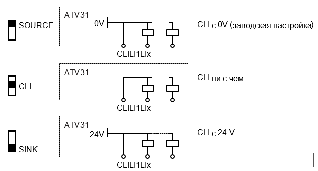
Переключатель дискретных входов
Этот переключатель назначает соединение общего вывода дискретных входов с 0 В, 24 В или ни с чем.
Программирование параметров ПЧ
Доступ к меню

Пример изменения параметров

Конфигурирование параметра bFr
Этот параметр можно изменять только при остановленном двигателе и при отсутствии команды пуска.

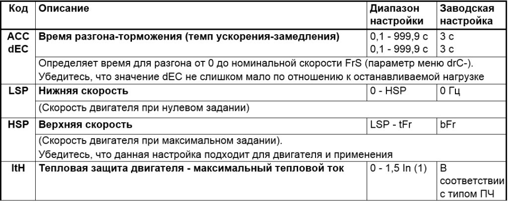
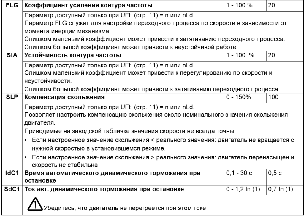
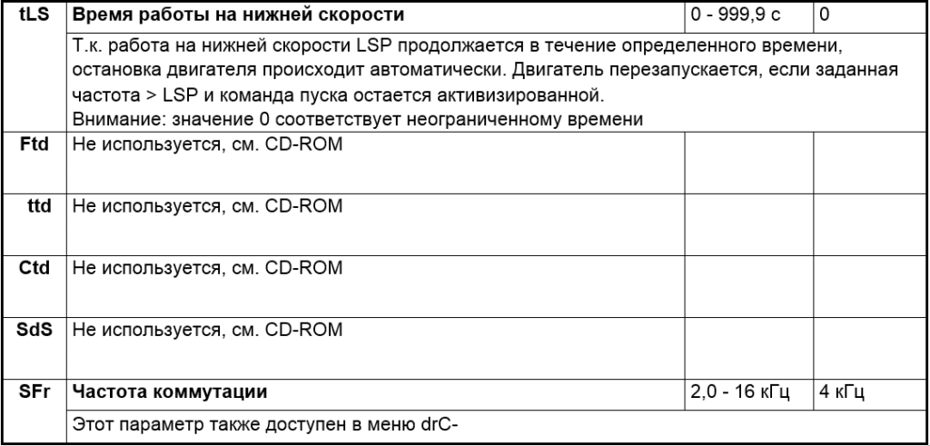
Настроечное меню SEt-
Настроечные параметры можно менять на ходу и при остановке.

Меню привода drC-
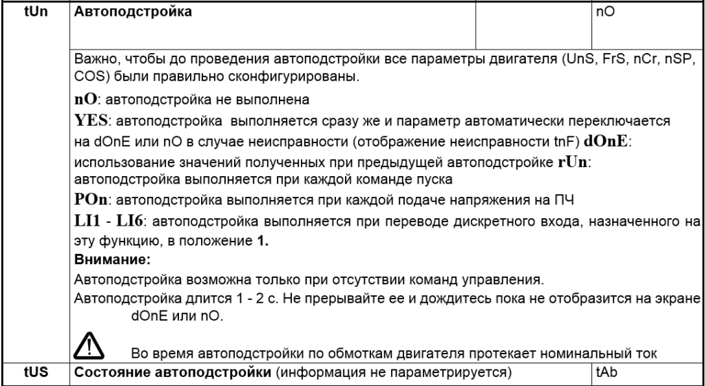
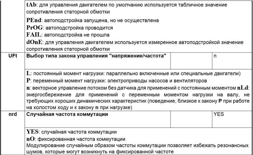
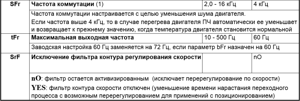
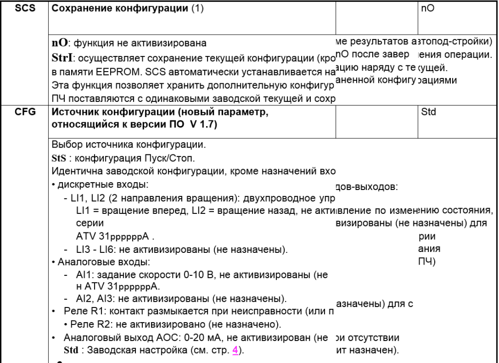
Параметры устанавливаются только при остановленном двигателе и отсутствии команды пуска, за исключением параметра tUn, который может запустить двигатель.
Оптимизация производительности привода достигается за счет:
— введение в меню Drive значений с шильдика;
— включение автоматической регулировки (для стандартного асинхронного двигателя).



Меню входов-выходов I-O-
Параметры настраиваются только при остановленном двигателе и при отсутствии команды пуска.

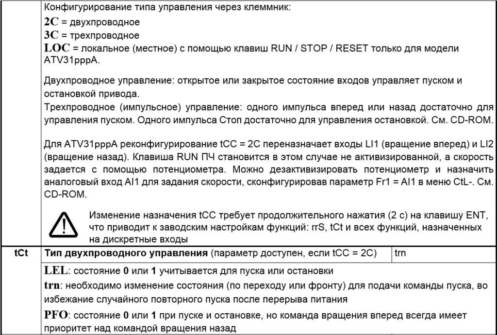


Меню контроля SUP-
Параметры доступны на ходу и при остановке.
Некоторые функции включают множество параметров. Чтобы упростить программирование и избежать утомительного просмотра параметров, эти функции сгруппированы в подменю.
Подменю, как и меню, обозначаются тире справа от кода, например: LIF-.
Во время работы преобразователя на экран выводится значение одного из контролируемых параметров. По умолчанию отображается выходная частота напряжения, подаваемого на двигатель (параметр rFr). Когда отображается новый требуемый параметр управления, требуется длительное нажатие (2 с) на кнопку ENT, чтобы подтвердить изменение параметра и сохранить его. После этого значение этого параметра будет отображаться в рабочем режиме (даже после отключения питания).
Если новый выбор не подтверждается долгим нажатием клавиши ENT, дисплей вернется к предыдущему параметру после отключения питания.
Примечание. После сбоя сети или сбоя питания всегда отображается параметр состояния инвертора (например, rdY). Выбранный параметр будет отображаться после подачи команды запуска.
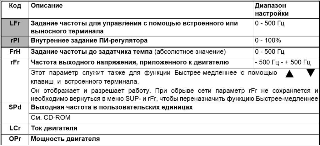
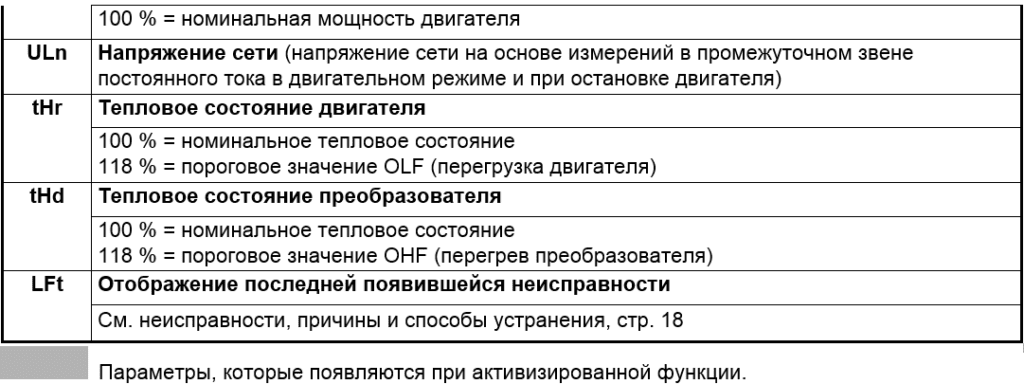
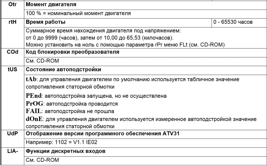

Примечание: Полный список параметров доступен в файле в конце страницы.
Список ошибок и способы устранения
Сбрасываемые неисправности
| Неисправность | Возможная причина | Процедура проверки |
| COF Неисправность CANopen | • Обрыв связи по шине CANopen | Проверьте коммуникационную линиюОбратитесь к специальной документации |
| CrF Зарядная цепь конденсаторов | • Неисправность управления реле нагрузки или повреждение нагрузочного сопротивления | • Замените преобразователь |
| EEF Неисправность EEPROM | • Неисправность внутренней памяти | Проверьте окружение (электромагнитную совместимость) Замените преобразователь |
| InF Внутренняя неисправность | К.З. источника 10 В Внутренняя неисправность | Проверьте цепи, подключенные к источнику 10 ВПроверьте подключение входов AI1 и AI2 и подключение к разъему RJ45 • Проверьте окружение (электромагнитную совместимость) Замените преобразователь |
| LFF Обрыв сигнала 4-20 мA | • Обрыв задания 4-20 мA на входе AI3 | • Проверьте подключение на входе AI3 |
| ObF Перенапряжение при торможении | • Слишком быстрое торможение или активная приводная нагрузка | Увеличьте время торможения Подключите, если это необходимо, тормозной модуль и сопротивлениеАктивизируйте функцию brA, если она совместима с применением |
| OCF Перегрузка по току | Параметры меню SEt- и drC- не корректныСлишком большой момент инерции или приводная нагрузкаМеханическая блокировка ротора | Проверьте параметры SEt- и drC- • Проверьте правильность выбора системы ПЧ-двигатель-нагрузкаПроверьте состояние механизма |
| OHF Перегрузка преобразователя | • Слишком высокая температура преобразователя | • Проверьте нагрузку двигателя, вентиляцию ПЧ, его окружение. Дождитесь его охлаждения для перезапуска |
| OLF Перегрузка двигателя | Срабатывание тепловой защиты из-за длительной перегрузкиОшибочное значение параметра rSC | Проверьте настройку ItH (стр. 11) тепловой защиты, нагрузку двигателя. Дождитесь его охлаждения для перезапускаПовторите измерение параметра rSC (стр. 13) |
| OPF Обрыв фазы двигателя | Обрыв фазы на выходе ПЧВыходной контактор разомкнутДвигатель не подключен или слишком мала мощностьВнезапная неустойчивость тока двигателя | Проверьте подключение ПЧ к двигателюВ случае использования выходного контактора настройте OPL на OAC (см. CD-ROM, меню FLt-)Испытание с двигателем малой мощности или без него: OPL = no (см. CD-ROM, меню FLt-)Проверьте и оптимизируйте параметры UFr (стр. 11), UnS и nCr (стр. 13) и сделайте автоподстройку tUn (стр. 14) |
| Неисправность | Возможная причина | Процедура проверки |
| OSF Перенапряжение | Очень высокое напряжение питанияСетевые возмущения | • Проверьте напряжение сети |
| PHF Обрыв фазы сетевого питания | Обрыв фазыИспользование однофазного питания для трехфазного ПЧ ATV31 • Несбалансированная нагрузка. Защита срабатывает только при нагрузке | Проверьте подключение силового питания и предохранителиИспользуйте трехфазную сетьЗаблокируйте неисправность установкой IPL = nO (см. CD-ROM) |
| SCF Короткое замыкание двигателя | Короткое замыкание или замыкание на землю на выходе ПЧБольшой ток утечки на землю на выходе ПЧ при параллельном под-ключении нескольких двигателей | Проверьте соединительные кабели между ПЧ и двигателем и изоляцию двигателяУменьшите частоту коммутацииДобавьте индуктивность, последовательно с двигателем |
| SLF Неисправность Modbus | Обрыв связи по шине Modbusназначение выносного терминала (LCC = YES) и отключенный терминал | Проверьте коммуникационную линиюОбрыв связи по шине Modbus • Проверьте связь с выносным терминалом |
| SOF Сверхскорость | • Неустойчивость или слишком большая приводная нагрузка | Проверьте параметры двигателя, коэффициенты усиления и усточивостиДобавьте тормозное сопротивлениеПроверьте правильность выбора системы ПЧ-двигатель-нагрузка |
| tnF Ошибка автоподстройки | Специальный двигатель или мощность двигателя не соответствует мощности преобразователяДвигатель не подключен | Используйте закон L или P (см. UFt, стр. 14) Проверьте наличие двигателя при автоподстройкеПри использовании выходного контактора замкните его при автоподстройке |
![]()
Неисправности, которые сбрасываются самостоятельно при исчезновении причины
| Неиспрвность | Возможная причина | Процедура проверки |
| CFF Неправильная конфигурация | • Текущая конфигурация не правильна | • Возвратитесь к заводским настройкам или загрузите ранее сохраненную подходящую конфигурацию. См. параметр FCS меню drC-, стр. 15 |
| CFI Ошибочная конфигурация, загруженная по сети | • Ошибочная конфигурация. Загруженная по сети конфигурация не соответствует ПЧ | Проверьте ранее загруженную конфигурациюЗагрузите подходящую конфигурацию |
| USF Недонапряжение | Слишком слабая сетьКратковременное снижение питанияНеисправность зарядного сопротивления | Проверьте напряжение и параметр напряженияЗамените преобразователь |
Скачать полную инструкцию.
RU
Заводская конфигурация
Преобразователь Altivar 31 настроен на заводе для наиболее распространенных применений:
• Дисплей: преобразователь готов (rdY), когда двигатель остановлен, а опорная частота двигателя отображается во время его работы.
• Частота питания двигателя (bFr): 50 ц.
• Приложение с постоянным крутящим моментом, бездатчиковое управление вектором потока. (УФТ = n).
• Метод нормального останова с установленной рампой замедления (Stt = rMP).
• Метод остановки в случае неисправности: остановка выбегом.
• Время разгона/торможения (ACC, dEC): 3 с.
• Низкая скорость (LSP): 0 ц.
• Высокая скорость (HSP): 50 ц.
• Тепловой ток двигателя (ItH) равен номинальному току двигателя (в зависимости от типа привода).
• Ток динамического торможения (SdC1) составляет 0,7 номинального тока преобразователя в течение 0,5 с.
• Автоматическая регулировка рампы в случае перенапряжения при торможении.
• Отсутствие автоматического перезапуска в случае сбоя.
• Частота переключения 4 кГц.
• Цифровые входы:
— LI1, LI2 (2 направления вращения): 2-проводное управление изменением состояния, LI1 = вращение вперед, LI2 = вращение назад, недоступно для серии ATV 31ppppppA.
— LI3, LI4: 4 опорные скорости (скорость 1 = опорная скорость или LSP, скорость 2 = 10 Гц, скорость 3 = 15 Гц, скорость 4 = 20 Гц).
— LI5 — LI6: не активирован (не назначен).
• Аналоговые входы:
— AI1: задание скорости 0–10 В, не активно (не назначено) для ATV серии 31ppppppA.
— AI2: дополнительный ввод скорости 0±10В.
— AI3: 4-20 мА не активирован (не назначен).
• Реле R1: контакт размыкается при неисправности (или когда привод обесточен).
• Реле R2: не активировано (не назначено).
• Аналоговый выход AOC: 0-20 мА, не активирован (не назначен).
Схема подключения преобразователя
- Сетевой дроссель по выбору (одно- или трехфазный)
- Контакты реле неисправности для дистанционного контроля состояния преобразователя
Переключатель дискретных входов
Этот переключатель назначает соединение общего вывода дискретных входов с 0 В, 24 В или ни с чем.
Программирование параметров ПЧ
Доступ к меню
Пример изменения параметров
Конфигурирование параметра bFr
Этот параметр можно изменять только при остановленном двигателе и при отсутствии команды пуска.
Настроечное меню SEt-
Настроечные параметры можно менять на ходу и при остановке.
Меню привода drC-
Параметры устанавливаются только при остановленном двигателе и отсутствии команды пуска, за исключением параметра tUn, который может запустить двигатель.
Оптимизация производительности привода достигается за счет:
— введение в меню Drive значений с шильдика;
— включение автоматической регулировки (для стандартного асинхронного двигателя).
Меню входов-выходов I-O-
Параметры настраиваются только при остановленном двигателе и при отсутствии команды пуска.
Меню контроля SUP-
Параметры доступны на ходу и при остановке.
Некоторые функции включают множество параметров. Чтобы упростить программирование и избежать утомительного просмотра параметров, эти функции сгруппированы в подменю.
Подменю, как и меню, обозначаются тире справа от кода, например: LIF-.
Во время работы преобразователя на экран выводится значение одного из контролируемых параметров. По умолчанию отображается выходная частота напряжения, подаваемого на двигатель (параметр rFr). Когда отображается новый требуемый параметр управления, требуется длительное нажатие (2 с) на кнопку ENT, чтобы подтвердить изменение параметра и сохранить его. После этого значение этого параметра будет отображаться в рабочем режиме (даже после отключения питания).
Если новый выбор не подтверждается долгим нажатием клавиши ENT, дисплей вернется к предыдущему параметру после отключения питания.
Примечание. После сбоя сети или сбоя питания всегда отображается параметр состояния инвертора (например, rdY). Выбранный параметр будет отображаться после подачи команды запуска.
Примечание: Полный список параметров доступен в файле в конце страницы.
Список ошибок и способы устранения
Сбрасываемые неисправности
| Неисправность | Возможная причина | Процедура проверки |
| COF Неисправность CANopen | • Обрыв связи по шине CANopen | Проверьте коммуникационную линиюОбратитесь к специальной документации |
| CrF Зарядная цепь конденсаторов | • Неисправность управления реле нагрузки или повреждение нагрузочного сопротивления | • Замените преобразователь |
| EEF Неисправность EEPROM | • Неисправность внутренней памяти | Проверьте окружение (электромагнитную совместимость) Замените преобразователь |
| InF Внутренняя неисправность | К.З. источника 10 В Внутренняя неисправность | Проверьте цепи, подключенные к источнику 10 ВПроверьте подключение входов AI1 и AI2 и подключение к разъему RJ45 • Проверьте окружение (электромагнитную совместимость) Замените преобразователь |
| LFF Обрыв сигнала 4-20 мA | • Обрыв задания 4-20 мA на входе AI3 | • Проверьте подключение на входе AI3 |
| ObF Перенапряжение при торможении | • Слишком быстрое торможение или активная приводная нагрузка | Увеличьте время торможения Подключите, если это необходимо, тормозной модуль и сопротивлениеАктивизируйте функцию brA, если она совместима с применением |
| OCF Перегрузка по току | Параметры меню SEt- и drC- не корректныСлишком большой момент инерции или приводная нагрузкаМеханическая блокировка ротора | Проверьте параметры SEt- и drC- • Проверьте правильность выбора системы ПЧ-двигатель-нагрузкаПроверьте состояние механизма |
| OHF Перегрузка преобразователя | • Слишком высокая температура преобразователя | • Проверьте нагрузку двигателя, вентиляцию ПЧ, его окружение. Дождитесь его охлаждения для перезапуска |
| OLF Перегрузка двигателя | Срабатывание тепловой защиты из-за длительной перегрузкиОшибочное значение параметра rSC | Проверьте настройку ItH (стр. 11) тепловой защиты, нагрузку двигателя. Дождитесь его охлаждения для перезапускаПовторите измерение параметра rSC (стр. 13) |
| OPF Обрыв фазы двигателя | Обрыв фазы на выходе ПЧВыходной контактор разомкнутДвигатель не подключен или слишком мала мощностьВнезапная неустойчивость тока двигателя | Проверьте подключение ПЧ к двигателюВ случае использования выходного контактора настройте OPL на OAC (см. CD-ROM, меню FLt-)Испытание с двигателем малой мощности или без него: OPL = no (см. CD-ROM, меню FLt-)Проверьте и оптимизируйте параметры UFr (стр. 11), UnS и nCr (стр. 13) и сделайте автоподстройку tUn (стр. 14) |
| Неисправность | Возможная причина | Процедура проверки |
| OSF Перенапряжение | Очень высокое напряжение питанияСетевые возмущения | • Проверьте напряжение сети |
| PHF Обрыв фазы сетевого питания | Обрыв фазыИспользование однофазного питания для трехфазного ПЧ ATV31 • Несбалансированная нагрузка. Защита срабатывает только при нагрузке | Проверьте подключение силового питания и предохранителиИспользуйте трехфазную сетьЗаблокируйте неисправность установкой IPL = nO (см. CD-ROM) |
| SCF Короткое замыкание двигателя | Короткое замыкание или замыкание на землю на выходе ПЧБольшой ток утечки на землю на выходе ПЧ при параллельном под-ключении нескольких двигателей | Проверьте соединительные кабели между ПЧ и двигателем и изоляцию двигателяУменьшите частоту коммутацииДобавьте индуктивность, последовательно с двигателем |
| SLF Неисправность Modbus | Обрыв связи по шине Modbusназначение выносного терминала (LCC = YES) и отключенный терминал | Проверьте коммуникационную линиюОбрыв связи по шине Modbus • Проверьте связь с выносным терминалом |
| SOF Сверхскорость | • Неустойчивость или слишком большая приводная нагрузка | Проверьте параметры двигателя, коэффициенты усиления и усточивостиДобавьте тормозное сопротивлениеПроверьте правильность выбора системы ПЧ-двигатель-нагрузка |
| tnF Ошибка автоподстройки | Специальный двигатель или мощность двигателя не соответствует мощности преобразователяДвигатель не подключен | Используйте закон L или P (см. UFt, стр. 14) Проверьте наличие двигателя при автоподстройкеПри использовании выходного контактора замкните его при автоподстройке |
![]()
Неисправности, которые сбрасываются самостоятельно при исчезновении причины
| Неиспрвность | Возможная причина | Процедура проверки |
| CFF Неправильная конфигурация | • Текущая конфигурация не правильна | • Возвратитесь к заводским настройкам или загрузите ранее сохраненную подходящую конфигурацию. См. параметр FCS меню drC-, стр. 15 |
| CFI Ошибочная конфигурация, загруженная по сети | • Ошибочная конфигурация. Загруженная по сети конфигурация не соответствует ПЧ | Проверьте ранее загруженную конфигурациюЗагрузите подходящую конфигурацию |
| USF Недонапряжение | Слишком слабая сетьКратковременное снижение питанияНеисправность зарядного сопротивления | Проверьте напряжение и параметр напряженияЗамените преобразователь |
Скачать полную инструкцию.
RU

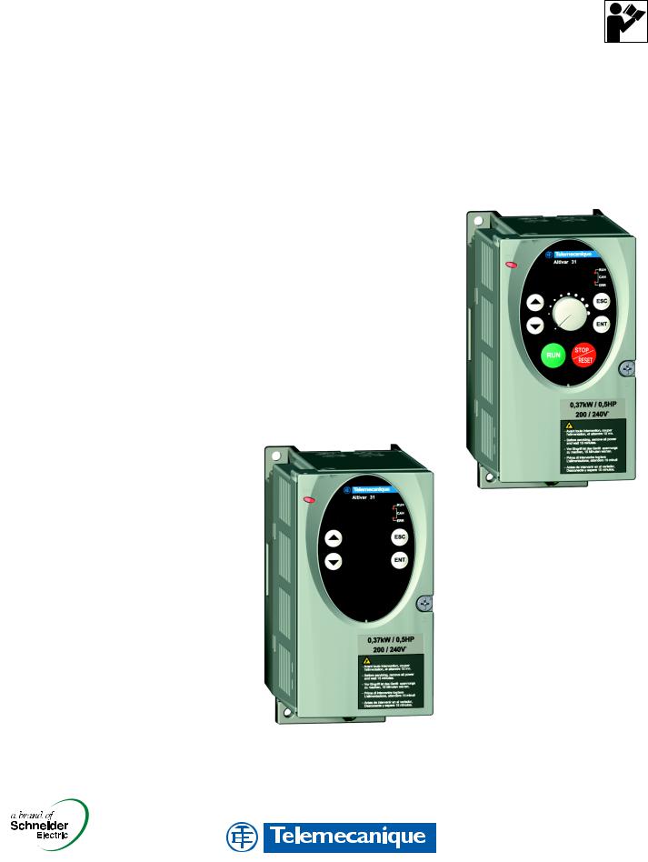
Altivar® 31
Adjustable Speed Drive Controllers
Variadores de velocidad ajustable
Variateurs de vitesse
Programming Manual
Manual de programación
Guide de programmation
Retain for future use. / Conservar para uso futuro. /
À conserver pour usage ultérieur.
Altivar® 31 Adjustable Speed Drive Controllers
Programming Manual . . . . . . . . . . . . . . . . . . . . . . . . . 5
Variadores de velocidad Ajustable Altivar® 31
Manual de programación . . . . . . . . . . . . . . . . . . . . . .99
Variateurs de vitesse Altivar® 31
Guide de programmation . . . . . . . . . . . . . . . . . . . . 193
|
© 2004 Schneider Electric All Rights Reserved |
3 |

|
4 |
© 2004 Schneider Electric All Rights Reserved |

|
VVDED303042NAR6/04 |
Altivar® 31 Programming Manual |
|
|
06/2004 |
Contents |
|
|
SECTION 1: INTRODUCTION |
Product Range ……………………………………………………………………………….. |
7 |
|
About This Document ……………………………………………………………………… |
7 |
|
|
Hazard Categories and Special Symbols …………………………………………… |
8 |
|
|
Product Support ……………………………………………………………………………… |
8 |
|
|
Start-Up Overview …………………………………………………………………………… |
9 |
|
|
Preliminary Recommendations ……………………………………………………….. |
10 |
|
|
Precautions …………………………………………………………………………….. |
10 |
|
|
Starting from Line Power …………………………………………………………… |
11 |
|
|
Power Up after a Manual Fault Reset or Stop Command ………………. |
11 |
|
|
Test on a Low Power Motor or without a Motor …………………………….. |
11 |
|
|
Using Motors in Parallel ……………………………………………………………. |
11 |
|
|
Operation on an Impedance Grounded System ……………………………. |
11 |
|
|
Programming Recommendations ……………………………………………….. |
11 |
|
|
Factory Settings ……………………………………………………………………………. |
12 |
|
|
Drive Thermal Protection ……………………………………………………………….. |
13 |
|
|
Ventilation ……………………………………………………………………………….. |
13 |
|
|
Motor Thermal Protection ………………………………………………………………. |
14 |
|
|
SECTION 2: PROGRAMMING |
Drive Keypad Display …………………………………………………………………….. |
16 |
|
ATV31•••••• Controllers …………………………………………………………….. |
16 |
|
|
ATV31••••••A Controllers …………………………………………………………… |
16 |
|
|
Key Functions ………………………………………………………………………….. |
17 |
|
|
nSt: Freewheel Stop …………………………………………………………………. |
17 |
|
|
Remote Keypad Display ………………………………………………………………… |
18 |
|
|
Saving and Loading Configurations ……………………………………………. |
18 |
|
|
Accessing the Menus …………………………………………………………………….. |
19 |
|
|
Accessing the Parameters ……………………………………………………………… |
20 |
|
|
bFr Parameter …………………………………………………………………………. |
20 |
|
|
Function Compatibility ……………………………………………………………………. |
21 |
|
|
Logic and Analog Input Application Functions …………………………………… |
22 |
|
|
SECTION 3: MENUS |
Settings Menu SEt- ……………………………………………………………………….. |
25 |
|
Drive Control Menu drC- ………………………………………………………………… |
29 |
|
|
I/O Menu I-O- ……………………………………………………………………………….. |
33 |
|
|
Control Menu CtL- …………………………………………………………………………. |
36 |
|
|
Control Channels ……………………………………………………………………… |
36 |
|
|
Parameter LAC ………………………………………………………………………… |
37 |
|
|
Parameter LAC = L1 or L2 ………………………………………………………… |
38 |
|
|
Parameter LAC = L3 ………………………………………………………………… |
39 |
|
|
Reference Channel for LAC = L1 or …………………………………………… |
41 |
|
|
Control Channel for LAC = L1 or L2 ……………………………………………. |
42 |
|
|
Reference Channel for LAC = L3 ……………………………………………….. |
43 |
|
|
Control Channel for LAC = L3: |
||
|
CHCF = SIM, Combined Reference and Control ………………………….. |
44 |
|
|
Control Channel for LAC = L3: |
||
|
CHCF = SEP, Mixed Mode (Separate Reference and Control) ………. |
45 |
|
|
Application Functions Menu FUn- ……………………………………………………. |
50 |
|
|
Summing Inputs ………………………………………………………………………. |
56 |
|
|
Preset Speeds …………………………………………………………………………. |
57 |
|
|
+/- Speed ………………………………………………………………………………… |
61 |
|
|
PI Regulator ……………………………………………………………………………. |
64 |
|
|
Manual–Automatic Operation with PI Regulator …………………………… |
66 |
|
|
Brake Control ………………………………………………………………………….. |
70 |
|
|
Management of Limit Switches ………………………………………………….. |
76 |
|
|
Fault Menu FLt- …………………………………………………………………………….. |
78 |
|
|
Communication Menu COM- ………………………………………………………….. |
82 |
|
|
Display Menu SUP- ……………………………………………………………………….. |
84 |
ENGLISH
|
© 2004 Schneider Electric All Rights Reserved |
5 |

ENGLISH
|
Altivar® 31 Programming Manual |
VVDED303042NAR6/04 |
||
|
Contents |
06/2004 |
||
|
SECTION 4: MAINTENANCE AND TROUBLE- |
Precautions ………………………………………………………………………………….. |
87 |
|
|
SHOOTING |
Routine Maintenance …………………………………………………………………….. |
87 |
|
|
Normal Display ……………………………………………………………………………… |
87 |
||
|
Fault Display ………………………………………………………………………………… |
87 |
||
|
Drive Controller Does Not Start, No Fault Displayed |
……………………… 87 |
||
|
Clearing Faults ………………………………………………………………………… |
88 |
||
|
Faults Which Cannot Be Automatically Reset ………………………………. |
88 |
||
|
Faults Which Can Be Automatically Reset …………………………………… |
89 |
||
|
Faults That Reset When the Fault Is Cleared ………………………………. |
90 |
||
|
Configuration Settings Tables …………………………………………………………. |
90 |
||
|
Drive Controller and Customer ID ………………………………………………. |
91 |
||
|
1st level Adjustment Parameter ………………………………………………….. |
91 |
||
|
Settings Menu …………………………………………………………………………. |
91 |
||
|
Drive Control Menu……………………………………………………………………. |
92 |
||
|
I/O Menu ………………………………………………………………………………… |
92 |
||
|
Control Menu ………………………………………………………………………….. |
92 |
||
|
Application Functions Menu ………………………………………………………. |
93 |
||
|
Application Functions Menu ………………………………………………………. |
94 |
||
|
Fault Menu ………………………………………………………………………………. |
95 |
||
|
Communication Menu ……………………………………………………………….. |
95 |
||
|
Index of Parameter Codes ……………………………………………………………… |
96 |
||
|
Index of Functions …………………………………………………………………………. |
97 |
|
6 |
© 2004 Schneider Electric All Rights Reserved |

|
VVDED303042NAR6/04 |
Section 1: Introduction |
|
06/2004 |
Product Range |
SECTION 1: INTRODUCTION
|
PRODUCT RANGE |
The Altivar 31 (ATV31) family of adjustable frequency AC drive controllers is |
|
used for controlling three-phase asynchronous motors. The controllers |
|
|
range from: |
|
|
• 0.25 to 3 hp (0.18 to 2.2 kW), 208/230/240 V, single-phase input |
|
|
• 0.25 to 20 hp (0.18 to 15 kW), 208/230/240 V, three-phase input |
|
|
• 0.5 to 20 hp (0.37 to 15 kW), 400/460/480 V, three-phase input |
|
|
• 1 to 20 hp (0.75 to 15 kW), 525/575/600 V, three-phase input |
|
|
Some ATV31 controllers are available with a reference potentiometer, a run |
|
|
button, and a stop/reset button. These controllers are designated as |
|
|
ATV31••••••A controllers throughout this manual. The symbol “•” in a catalog |
|
|
number designates parts of the number that vary with the rating. |
|
|
ABOUT THIS DOCUMENT |
This manual contains programming instructions for ATV31 drive controllers. |
|
The following documentation is also provided with the controller: |
|
|
• Altivar 31 Installation Manual, VVDED303041US |
|
|
• Altivar 31 Start-Up Guide, VVDED303043US |
|
|
Refer to the ATV31 Installation Manual for instructions on receiving, |
|
|
inspection, mounting, installation, and wiring. Refer to the ATV31 Start-Up |
|
|
Guide for instructions on bringing the drive controller into service with the |
|
|
factory configuration. |
|
|
Refer to the Index of Parameter Codes and the Index of Functions on |
|
|
pages 96–97 of for an alphabetical index of the codes and functions |
|
|
discussed in this manual. |
|
|
NOTE: Throughout this manual, and on the drive keypad display, a dash |
|
|
appears after menu and sub-menu codes to differentiate them from |
|
|
parameter codes. For example, SEtis a menu, but ACC is a parameter. |
ENGLISH
|
© 2004 Schneider Electric All Rights Reserved |
7 |
ENGLISH
|
Section 1: Introduction |
VVDED303042NAR6/04 |
|
Hazard Categories and Special Symbols |
06/2004 |
HAZARD CATEGORIES AND SPECIAL SYMBOLS
The following symbols and special messages may appear in this manual or on the equipment to warn of potential hazards.
A lightening bolt or ANSI man symbol in a “Danger” or “Warning” safety label on the equipment indicates an electrical hazard which will result in personal injury if the instructions are not followed.
An exclamation point symbol in a safety message in the manual indicates potential personal injury hazards. Obey all safety messages introduced by this symbol to avoid possible injury or death.
Lightening Bolt
|
ANSI Man |
||||
|
Exclamation Point |
||||
|
DANGER |
||||
|
DANGER indicates an imminently hazardous situation which, if not |
||||
|
avoided, will result in death or serious injury. |
||||
|
WARNING |
||||
|
WARNING indicates a potentially hazardous situation which, if not |
||||
|
avoided, can result in death or serious injury. |
||||
|
CAUTION |
||||
|
CAUTION indicates a potentially hazardous situation which, if not |
||||
|
avoided, can result in minor or moderate injury. |
||||
|
CAUTION |
||||
|
CAUTION, used without the safety alert symbol, indicates a potentially |
||||
|
hazardous situation which, if not avoided, can result in property damage. |
||||
|
PRODUCT SUPPORT |
For support and assistance, contact the Product Support Group. The |
|||
|
Product Support Group is staffed from 8:00 am until 6:00 pm Eastern time to |
||||
|
assist with product selection, start-up, and diagnosis of product or |
||||
|
application problems. Emergency phone support is available 24 hours a |
||||
|
day, 365 days a year. |
||||
|
Telephone |
919-266-8600 |
|||
|
Toll Free |
888-Square D (888-778-2733) |
|||
|
|
drive.products.support@us.schneider-electric.com |
|||
|
Fax |
919-217-6508 |
|
8 |
© 2004 Schneider Electric All Rights Reserved |

|
VVDED303042NAR6/04 |
Section 1: Introduction |
|
|
06/2004 |
Start-Up Overview |
|
|
START-UP OVERVIEW |
The following procedure is an overview of the minimum steps necessary for |
|
|
bringing an ATV31 drive controller into service. Refer to the ATV31 |
||
|
Installation Manual for the mounting, wiring, and bus voltage measurement |
||
|
steps. Refer to the appropriate sections of this manual for the programming |
||
|
steps. |
||
|
1. |
Mount the drive controller. Refer to the ATV31 Installation Manual. |
|
|
2. |
Make the following connections to the drive controller. Refer to the |
|
|
ATV31 Installation Manual: |
||
|
— Connect the grounding conductors. |
||
|
— Connect the line supply. Ensure that it is within the voltage range of |
||
|
the drive controller. |
||
|
— Connect the motor. Ensure that its rating corresponds to the drive |
||
|
controller’s voltage. |
||
|
3. |
Power up the drive controller, but do not give a run command. |
|
|
4. |
Configure bFr (motor nominal frequency) if it is other than 50 Hz. bFr |
|
|
appears on the display the first time the drive controller is powered up. It |
||
|
can be accessed in the drCmenu (page 29) anytime. |
||
|
5. |
Configure the parameters in the drCmenu if the factory configuration is |
|
|
not suitable. Refer to page 12 for the factory settings. |
||
|
6. |
Configure the parameters in the I-O-, CtL-, and FUnmenus if the |
|
|
factory configuration is not suitable. Refer to page 12 for the factory |
||
|
settings. |
||
|
7. |
Configure the following parameters in the SEtmenu (pages 25–29): |
|
|
— ACC (acceleration) and dEC (deceleration) |
||
|
— LSP (low speed when the reference is zero) and HSP (high speed |
||
|
when the reference is at its maximum) |
||
|
— ItH (motor thermal protection) |
||
|
8. |
Remove power from the drive controller and follow the bus voltage |
|
|
measurement procedure in the ATV31 Installation Manual. Then |
||
|
connect the control wiring to the logic and analog inputs. |
||
|
9. |
Power up the drive controller, then issue a run command via the logic |
|
|
input (refer to the ATV31 Start-Up Guide). |
||
|
10. Adjust the speed reference. |
ENGLISH
|
© 2004 Schneider Electric All Rights Reserved |
9 |

ENGLISH
|
Section 1: Introduction |
VVDED303042NAR6/04 |
|
Preliminary Recommendations |
06/2004 |
PRELIMINARY RECOMMENDATIONS
|
Precautions |
Before powering up and configuring the drive controller, read and observe |
|
the following precautions. |

UNINTENDED EQUIPMENT OPERATION
• Before powering up and configuring the drive controller, ensure that the logic inputs are switched off (State 0) to prevent unintended starting.
• An input assigned to the run command may cause the motor to start immediately upon exiting the configuration menus.
Failure to follow these instructions will result in death or serious injury.

LOSS OF CONTROL
• The designer of any control scheme must consider the potential failure modes of control paths and, for certain critical control functions, provide a means to achieve a safe state during and after a path failure.
• Examples of critical control functions are Emergency Stop and Overtravel Stop.
• Separate or redundant control paths must be provided for critical control functions.
Failure to follow these instructions can result in death, serious injury, or equipment damage.
CAUTION
DAMAGED EQUIPMENT
Do not operate or install any drive controller that appears damaged.
Failure to follow this instruction can result in equipment damage.
|
10 |
© 2004 Schneider Electric All Rights Reserved |

|
VVDED303042NAR6/04 |
Section 1: Introduction |
|
06/2004 |
Preliminary Recommendations |
Starting from Line Power
Power Up after a Manual Fault Reset or Stop Command
Test on a Low Power Motor or without a Motor
Using Motors in Parallel
Operation on an Impedance Grounded System
Programming Recommendations
If you are starting the drive controller from line power, ensure that parameter tCt is not set to trn (see page 33), and limit operations of the line contactor to fewer than one per minute to avoid premature failure of the filter capacitors and precharge resistors. The recommended method of control is through inputs LI1 to LI6. The motor thermal state memory returns to zero when line power is removed from the drive controller.
If parameter tCt is at its factory setting (trn), when the drive controller is powered up after a manual fault reset or a stop command, the forward, reverse, and DC injection stop commands must be reset for the drive controller to start. If they are not reset, the drive controller will display nSt and will not start. If automatic restart is configured (parameter Atr in the FLtmenu, see page 79) the reset is not necessary.
With the factory configuration, motor phase loss detection (OPL) is active. To check the drive controller in a test or maintenance environment without having to switch to a motor with the same rating as the drive controller, disable motor phase loss detection and configure the voltage/frequency ratio (UFt) to L, constant torque (see page 31). The drive controller will not provide motor thermal protection if the motor current is less than 0.2 times the nominal drive current.
When using motors in parallel, configure the voltage/frequency ratio, UFt, to L (constant torque) and provide an alternate means of thermal protection on every motor. The drive controller cannot provide adequate motor thermal protection for each motor.
When using the drive controller on a system with an isolated or impedance grounded neutral, use a permanent insulation monitor compatible with nonlinear loads.
ATV31••••••M21 and N4 drive controllers feature built-in radio frequency interference (RFI) filters which have capacitors to ground. These filters can be disconnected from ground when using the drive controller on an impedance grounded system to increase the operating life of their capacitors. Refer to the ATV31 Installation Manual for more information.
Refer to “Start-Up Overview” on page 9 for the minimum programming steps necessary for bringing the drive controller into service.
Use the configuration settings tables beginning on page 91 to prepare and record the drive configuration before programming the drive controller. It is always possible to return to the factory settings by setting the FCS parameter to InI in the drC-, I-O-, CtL-, or FUnmenus. See pages 32, 35, 49, and 77.
When first commissioning an ATV31 drive controller for a 60 Hz system, perform a factory parameter reset. Be sure to set bFr to 60 Hz.
We recommend using the auto-tuning function to optimize the drive controller’s accuracy and response time. Auto-tuning measures the stator resistance of the motor to optimize the control algorithms. See page 31.
ENGLISH
1Throughout this manual, the symbol “•” in a catalog number denotes the portion of the number that varies with the drive controller rating.
|
© 2004 Schneider Electric All Rights Reserved |
11 |

Section 1: Introduction
Factory Settings
FACTORY SETTINGS
ENGLISH
VVDED303042NAR6/04
06/2004
The ATV31 drive controller is supplied ready for use in most applications, with the factory settings shown in Table 1.
|
Table 1: |
Factory Settings |
|||
|
Function |
Code |
Factory Setting |
||
|
rdY with motor stopped, |
||||
|
Display |
— |
motor frequency (for example, 50 Hz) with motor |
||
|
running |
||||
|
Motor frequency |
bFr |
50 Hz |
||
|
Type of voltage/frequency |
UFt |
n: sensorless flux vector control for constant |
||
|
ratio |
torque applications |
|||
|
Normal stop mode |
Stt |
Stn: normal stop on deceleration ramp |
||
|
Stop mode in the event of a |
EPL |
YES: freewheel stop |
||
|
fault |
||||
|
Linear ramps |
ACC, dEC |
3 seconds |
||
|
Low speed |
LSP |
0 Hz |
||
|
High speed |
HSP |
50 Hz |
||
|
Frequency loop gain |
FLG, StA |
Standard |
||
|
Motor thermal current |
ItH |
Nominal motor current (value depends on the |
||
|
drive controller rating) |
||||
|
DC injection braking |
SdC |
0.7 x nominal drive controller current for |
||
|
0.5 seconds |
||||
|
Deceleration ramp adaptation |
brA |
YES: automatic adaptation of the deceleration |
||
|
ramp in the event of overvoltage on braking |
||||
|
Automatic restart |
Atr |
nO: no automatic restart after a fault |
||
|
Switching frequency |
SFr |
4 kHz |
||
|
2-wire transition detection control: |
||||
|
LI1, LI2 |
LI1 = forward, LI2 = reverse. |
|||
|
Not assigned on ATV31••••••A1 drive controllers |
||||
|
4 preset speeds: |
||||
|
Logic inputs |
speed 1 = speed reference or LSP (see page 26) |
|||
|
LI3, LI4 |
speed 2 = 10 Hz |
|||
|
speed 3 = 15 Hz |
||||
|
speed 4 = 20 Hz |
||||
|
LI5, LI6 |
Not assigned |
|||
|
AI1 |
Speed reference 0–10 V. |
|||
|
Not assigned on ATV31••••••A1 drive controllers. |
||||
|
Analog inputs |
||||
|
AI2 |
Summed speed reference input 0 ±10 V |
|||
|
AI3 |
4–20 mA, not assigned |
|||
|
R1 |
The contact opens in the event of a fault or if |
|||
|
Relays |
power is removed from the drive controller. |
|||
|
R2 |
Not assigned |
|||
|
Analog output |
AOC |
0–20 mA, not assigned |
||
1ATV31••••••A range drive controllers have a reference potentiometer, a run button, and a stop/reset button. They are factory set for local control with the run button, the stop/reset button, and the reference potentiometer active. Logic inputs LI1 and LI2 and analog input AI1 are inactive (not assigned).
|
12 |
© 2004 Schneider Electric All Rights Reserved |
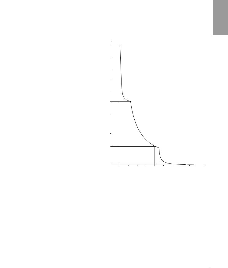
|
VVDED303042NAR6/04 |
Section 1: Introduction |
||||||||||||
|
06/2004 |
Drive Thermal Protection |
||||||||||||
|
DRIVE THERMAL PROTECTION |
Thermal protection of the drive controller is achieved with a positive |
||||||||||||
|
temperature coefficient (PTC) resistor on the heatsink or power module. In |
|||||||||||||
|
the event of an overcurrent, the drive controller trips to protect itself against |
|||||||||||||
|
overloads. Typical tripping points are: |
|||||||||||||
|
• Motor current is 185% of nominal drive controller current for 2 seconds |
|||||||||||||
|
• Motor current is 150% of nominal drive controller current for 60 seconds |
|||||||||||||
|
Time |
|||||||||||||
|
(seconds) |
5000 |
||||||||||||
|
3000 |
|||||||||||||
|
1000 |
|||||||||||||
|
200 |
|||||||||||||
|
160 |
|||||||||||||
|
100 |
|||||||||||||
|
60 |
|||||||||||||
|
2 |
|||||||||||||
|
0 |
|||||||||||||
|
1 |
1.1 |
1.2 |
1.3 |
1.4 |
1.5 |
1.6 |
1.7 |
1.8 |
1.9 |
||||
|
Motor current/drive controller In |
|||||||||||||
|
Ventilation |
The fan starts when the drive controller is powered up, but stops after |
||||||||||||
|
10 seconds if a run command is not received. The fan starts automatically |
|||||||||||||
|
when the drive controller receives an operating direction and reference. It |
|||||||||||||
|
stops a few seconds after motor speed is less than 0.2 Hz and injection |
|||||||||||||
|
braking is completed. |
ENGLISH
|
© 2004 Schneider Electric All Rights Reserved |
13 |
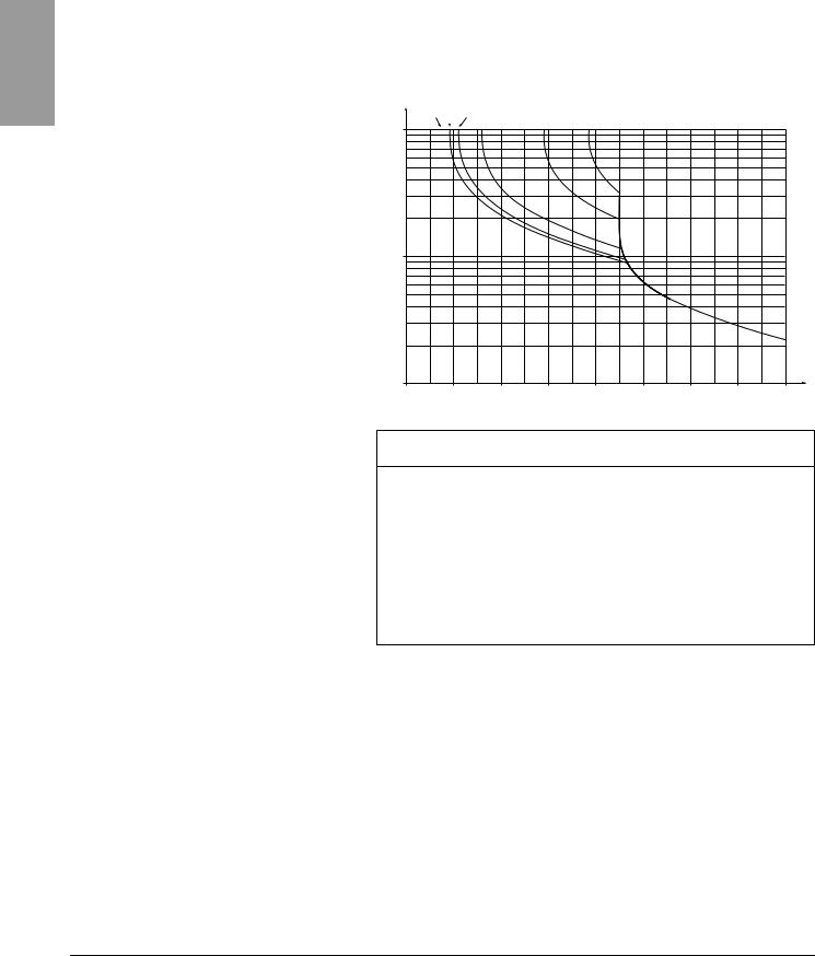
ENGLISH
|
Section 1: Introduction |
VVDED303042NAR6/04 |
|
Motor Thermal Protection |
06/2004 |
|
MOTOR THERMAL PROTECTION |
Motor thermal protection is achieved by continuous calculation of I2t. The |
|||
|
protection is available for self-cooled motors. |
||||
|
NOTE: The motor thermal state memory returns to zero when line power is |
||||
|
removed from the drive controller. |
||||
|
Trip time in seconds |
||||
|
1 Hz 3 Hz 5 Hz |
||||
|
10,000 |
10 Hz |
20 Hz |
50 Hz |
|
1,000
|
1000.7 |
0.8 |
0.9 |
1 |
1.1 |
1.2 |
1.3 |
1.4 |
1.5 |
Motor current/ItH
CAUTION
INADEQUATE MOTOR THERMAL PROTECTION
The use of external overload protection is required under the following conditions:
•Starting from line power
•Running multiple motors
•Running motors rated at less than 0.2 times the nominal drive current
•Using motor switching
Failure to follow this instruction can result in equipment damage.
Refer to “Preliminary Recommendations” on pages 10–11 for more information about external overload protection.
|
14 |
© 2004 Schneider Electric All Rights Reserved |

|
VVDED303042NAR6/04 |
Section 2: Programming |
|
06/2004 |
|
SECTION 2: PROGRAMMING
ENGLISH

UNQUALIFIED USER
•This equipment must be installed, programmed, and serviced only by qualified personnel.
•The application of this product requires expertise in the design and programming of control systems. Only persons with such expertise should be allowed to program, install, alter, and apply this product.
•Qualified personnel performing diagnostics or troubleshooting that requires electrical conductors to be energized must comply with NFPA 70 E — Standard for Electrical Safety Requirements for Employee Workplaces and OSHA Standards — 29 CFR Part 1910 Subpart S Electrical.
Failure to follow these instructions will result in death or serious injury.
|
© 2004 Schneider Electric All Rights Reserved |
15 |
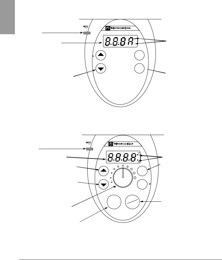
ENGLISH
|
Section 2: Programming |
VVDED303042NAR6/04 |
|
Drive Keypad Display |
06/2004 |
DRIVE KEYPAD DISPLAY
ATV31•••••• Controllers
Red LED
DC bus ON
Four 7-segment displays
Returns to the previous menu or 
displayed value
Advances to the next menu or parameter, or decreases the displayed value
Altivar 31

|
CAN |
2 CANopen status LEDs |

ESC 
ENT

|
ATV31••••••A Controllers |
ATV31••••••A controllers have a reference potentiometer, a run button, and |
|
a stop/reset button. |
|
Red LED |
Altivar 31 |
|
DC bus ON |
|
|
RUN |
|
|
Four 7-segment displays |
CAN |
|
ERR |
|
|
Returns to the previous menu or parameter, |
|
|
or increases the displayed value |
ESC |
|
Advances to the next menu or parameter, or |
ENT |
|
decreases the displayed value |
|
RUN |
STOP |
||
|
Reference potentiometer: |
RESET |
||
|
Active if parameter Fr1 in the CtLmenu is |
|||
|
configured as AIP (see page 46) |
RUN button: Starts the motor in forward direction if parameter tCC in the I-O- menu is configured as LOC (see page 33)

Exits a menu or a parameter,
or clears the displayed value to return to the previous stored value

STOP/RESET button
Resets faults
Stops the motor:
•If tCC (I-O- menu) is not configured as LOC, pressing the STOP/RESET key commands a freewheel stop.
•If tCC (I-O- menu) is configured as LOC, stopping is on a ramp, but if injection braking is in progress, a freewheel stop takes place.
|
16 |
© 2004 Schneider Electric All Rights Reserved |

|
VVDED303042NAR6/04 |
Section 2: Programming |
||
|
06/2004 |
Drive Keypad Display |
||
|
Key Functions |
• Press and hold down (longer than 2 seconds) the |
or |
keys to |
|
scroll through the data quickly. |
•Pressing 

•To store the selection, press the ENT key.The display flashes when a value is stored.
|
A normal display with no fault present and no run command shows: |
||
|
• |
The value of one of the display parameters (see page 84). The default |
|
|
display is motor frequency, for example 43.0. In current limiting mode, |
||
|
the display flashes. |
||
|
• |
Init: Initialization sequence |
|
|
• |
rdY: Drive ready |
|
|
• |
dcb: DC injection braking in progress |
|
|
• |
nSt: Freewheel stop |
|
|
• |
FSt: Fast stop |
|
|
• |
tUn: Auto-tuning in progress |
|
|
If a fault is present, the display flashes. |
||
|
nSt: Freewheel Stop |
If the display shows the code nSt, one of the following conditions is |
|
|
indicated: |
||
|
1. |
With the factory configuration, when the drive controller is powered up |
|
|
after a manual fault reset or stop command, the forward, reverse, and |
||
|
DC injection stop commands must be reset for the drive controller to |
||
|
start. If they are not reset, the drive controller will display nSt and will not |
||
|
start. If automatic restart is configured, the reset is not necessary. |
||
|
2. |
If the reference channel or the control channel is assigned to Modbus or |
|
|
CANopen (see page 36), the drive controller will display nSt on power up |
||
|
and remain stopped until the communication bus sends a command. |
||
|
3. |
If a forward or reverse run command is present when the drive controller |
|
|
is powered up and the drive controller is set for 3-wire control or for |
2-wire control with “trn” transition (see page 33) the drive controller will display nSt and will not run until the run command is cycled and a valid speed reference is given.
ENGLISH
|
© 2004 Schneider Electric All Rights Reserved |
17 |
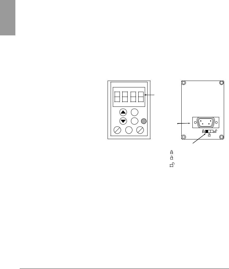
ENGLISH
|
Section 2: Programming |
VVDED303042NAR6/04 |
|
Remote Keypad Display |
06/2004 |
|
REMOTE KEYPAD DISPLAY |
The optional remote keypad display is a local control unit that can be wall- |
|
mounted on the door of an enclosure. It has a cable with connectors for |
|
|
connection to the drive serial link (refer to the manual supplied with the |
|
|
display). The remote keypad display has the same display and |
|
|
programming buttons as the drive controller, with the addition of a switch to |
|
|
lock access to the menu and three buttons for commanding the drive |
|
|
controller: |
|
|
• FWD/REV commands the direction of rotation. |
|
|
• RUN commands the motor to run. |
|
|
• STOP/RESET commands the motor to stop or resets a fault. Pressing |
|
|
the STOP/RESET button once stops the motor; pressing it a second |
|
|
time stops DC injection braking if it is configured. |
|
|
In order for the remote keypad display to be active, the tbr parameter in the |
|
|
COMmenu must remain at the factory setting, 19.2 (19,200 bps, see |
|
|
page 82). |
|
4-character |
|||
|
display |
|||
|
ESC |
|||
|
ENT |
Connector |
||
|
FWD |
RUN |
STOP |
|
|
REV |
RESET |
Access locking switch:
• Positions:
• Position:
settings and display are accessible (SEtand SUPmenus)
all menus can be accessed
|
NOTE: Password protection has priority over the access locking switch. See |
|
|
page 86. |
|
|
Placing the access locking switch in the locked position also prevents the |
|
|
drive settings from being accessed via the drive controller keypad. When |
|
|
the remote keypad display is disconnected, if the access locking |
|
|
switch is in the locked position, the drive controller keypad also |
|
|
remains locked. |
|
|
Saving and Loading Configurations |
Up to four complete configurations can be stored in the remote keypad |
|
display and transferred to other drive controllers of the same rating. Four |
|
|
different operations for the same device can also be stored on the terminal. |
|
|
See the SCS and FCS parameters in the drC-, I-O-, CtL-, or FUnmenus. |
|
|
See pages 32, 35, 49, and 77. |
|
18 |
© 2004 Schneider Electric All Rights Reserved |
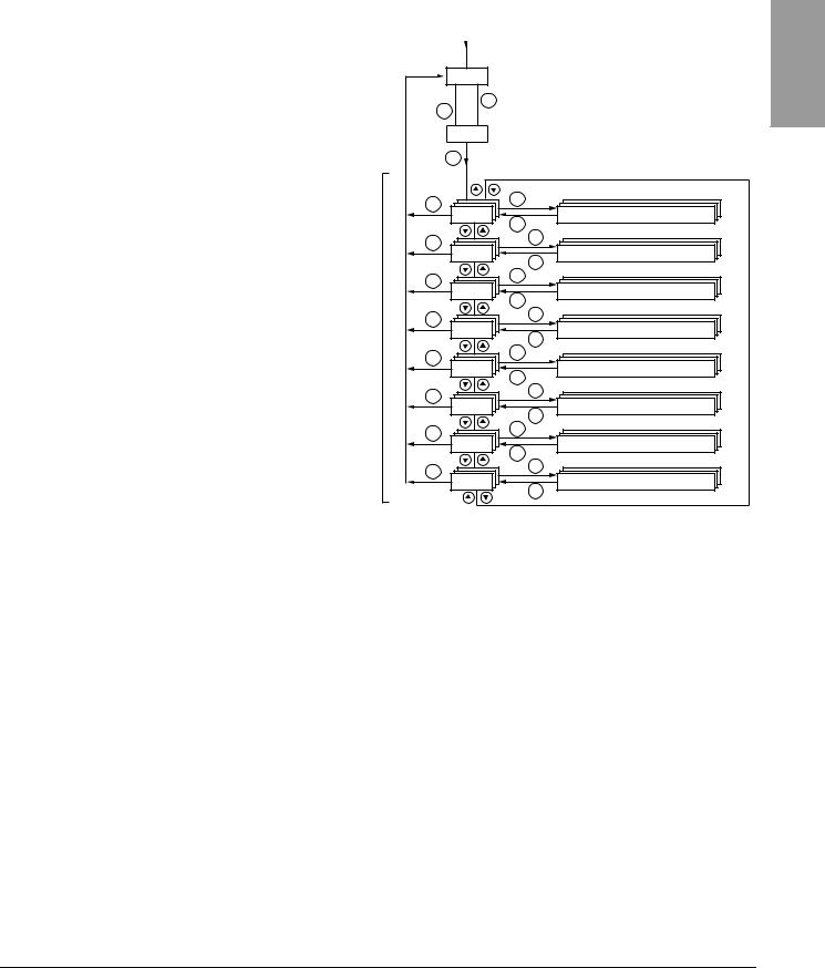
|
VVDED303042NAR6/04 |
Section 2: Programming |
|
06/2004 |
Accessing the Menus |
ACCESSING THE MENUS
Menus
Power-up
XXX Displays drive controller status (variable, see page 17)

ENT
Motor frequency (the factory setting is only visible bFr the first time the drive is powered up. See page 20.)
|
ENT |
||
|
ESC |
ENT |
|
|
Settings (page 25) |
||
|
SEt- |
||
|
ESC |
||
|
ESC |
ENT |
|
|
Drive control (page 29) |
||
|
drC- |
||
|
ESC |
||
|
ESC |
ENT |
|
|
I/O (page 33) |
||
|
I-O- |
||
|
ESC |
||
|
ESC |
ENT |
|
|
Control (page 36) |
||
|
CtL- |
||
|
ESC |
||
|
ESC |
ENT |
|
|
Functions (page 50) |
||
|
FUn- |
||
|
ESC |
||
|
ESC |
ENT |
|
|
Faults (page 78) |
||
|
FLt- |
||
|
ESC |
||
|
ESC |
ENT |
|
|
Communication (page 82) |
||
|
CON- |
||
|
ESC |
||
|
ESC |
ENT |
|
|
Monitoring (page 84) |
||
|
SUP- |
||
|
ESC |
For added convenience, some parameters can be accessed in more than one menu. For example, return to factory settings (FCS) and saving the configuration (SCS) are available in multiple menus.
NOTE: Throughout this guide, a dash appears after menu codes to differentiate them from parameter codes. For example, SEtis a menu, but ACC is a parameter.
ENGLISH
|
© 2004 Schneider Electric All Rights Reserved |
19 |
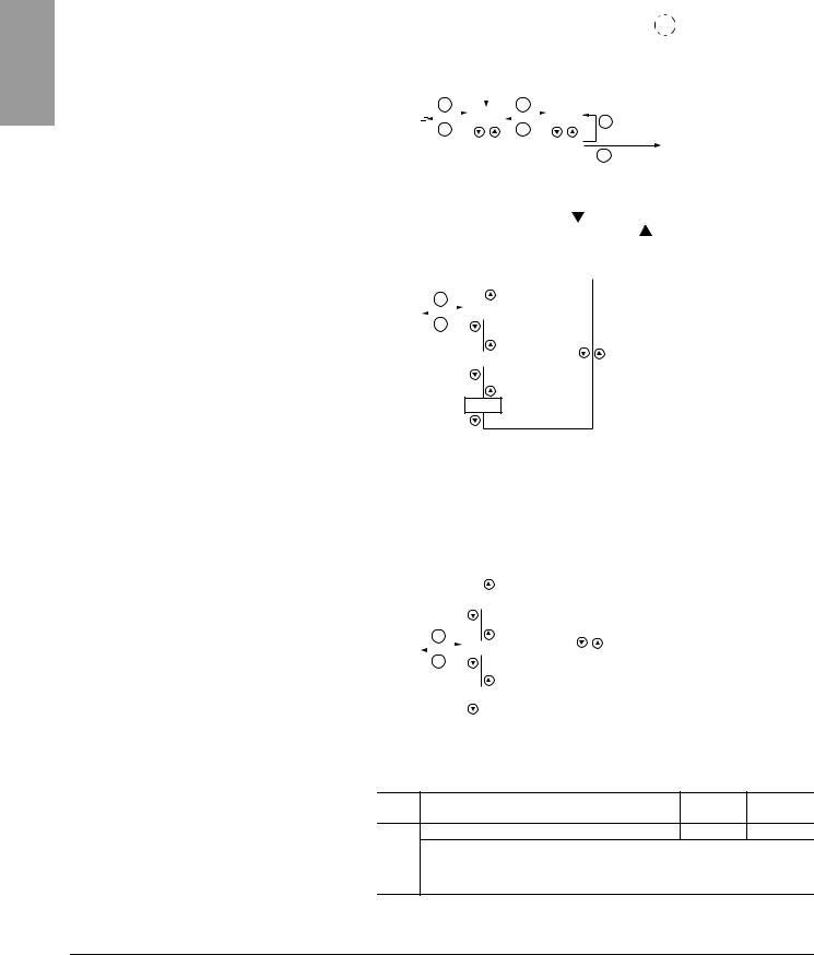
ENGLISH
|
Section 2: Programming |
VVDED303042NAR6/04 |
|
Accessing the Parameters |
06/2004 |
|
ACCESSING THE PARAMETERS |
The following figure illustrates how to access parameters and assign their |
|||||||||||||||||||||||||
|
values. To store the parameter value, press the ENT key. The display |
||||||||||||||||||||||||||
|
flashes when a value is stored. |
||||||||||||||||||||||||||
|
Menu |
Parameter |
Value Assignment |
||||||||||||||||||||||||
|
The display |
||||||||||||||||||||||||||
|
ENT |
ENT |
|||||||||||||||||||||||||
|
SEt- |
ACC |
15.0 |
ESC |
flashes when a |
||||||||||||||||||||||
|
ESC |
ESC |
value is stored. |
||||||||||||||||||||||||
|
dEC |
26.0 |
ENT |
26.0 |
|||||||||||||||||||||||
|
Next Parameter |
||||||||||||||||||||||||||
|
All of the menus are drop-down type menus. Once you have reached the |
||||||||||||||||||||||||||
|
last parameter in a list, press the |
key to return to the first parameter. |
|||||||||||||||||||||||||
|
From the first parameter in the list, press the |
key to jump to the last |
|||||||||||||||||||||||||
|
parameter. |
||||||||||||||||||||||||||
|
ENT |
||||||||||||||||||||||||||
|
1st |
||||||||||||||||||||||||||
|
Menu |
||||||||||||||||||||||||||
|
ESC |
||||||||||||||||||||||||||
|
nth |
||||||||||||||||||||||||||
last
If you have modified a parameter in a menu and you return to that menu without accessing another menu in the meantime, you will be taken directly to the parameter you last modified. See the illustration below. If you have accessed another menu or have restarted the drive controller since the modification, you will be taken to the first parameter in the menu. See the illustration above.
|
1st |
|||||||||||
|
ENT |
|||||||||||
|
Menu |
nth |
||||||||||
|
ESC |
|||||||||||
|
bFr Parameter |
last |
||||||||||
|
Motor frequency, bFr, can only be modified when the drive controller is |
|||||||||||
|
stopped and not receiving a run command. |
|||||||||||
|
Code |
Description |
Adjustment Factory |
|||||||||
|
range |
setting |
||||||||||
|
bFr |
Motor frequency |
50 or 60 Hz |
50 Hz |
||||||||
|
This is the first parameter displayed when the drive controller is first powered up. |
|||||||||||
|
bFr can be modified at any time in the drCmenu. |
|||||||||||
|
Modifying this parameter also modifies the values of the following parameters: HSP |
|||||||||||
|
(page 26), Ftd (page 29), FrS (page 30), and tFr (page 32). |
|
20 |
© 2004 Schneider Electric All Rights Reserved |

|
VVDED303042NAR6/04 |
Section 2: Programming |
|||||||||||||||||
|
06/2004 |
Function Compatibility |
|||||||||||||||||
|
FUNCTION COMPATIBILITY |
Automatic restart, catch on the fly, and reverse direction are only available |
|||||||||||||||||
|
as described below: |
||||||||||||||||||
|
• Automatic restart is only available in 2-wire control (tCC = 2C and |
||||||||||||||||||
|
tCt = LEL or PFO, see page 33). |
||||||||||||||||||
|
• Catch on the fly is only available in 2-wire control (tCC = 2C and |
||||||||||||||||||
|
tCt = LEL or PFO, see page 33). It is deactivated if automatic DC |
||||||||||||||||||
|
injection braking is configured as DC (AdC = Ct, see page 55). |
||||||||||||||||||
|
• Reverse direction is only available on ATV31••••••A controllers if local |
||||||||||||||||||
|
control is active (tCC = LOC, see page 33). |
||||||||||||||||||
|
The choice of application functions is limited by the number of I/O available |
||||||||||||||||||
|
and by the fact that some functions are incompatible with one another as |
||||||||||||||||||
|
illustrated in the figure below. Functions which are not listed in the figure are |
||||||||||||||||||
|
fully compatible. If there is an incompatibility between functions, the first |
||||||||||||||||||
|
function configured will prevent the others from being configured. |
||||||||||||||||||
|
switches |
||||||||||||||||||
|
Summing inputs |
1 |
Management of limit |
Preset speeds |
PI regulator |
Jog operation |
Brake sequence |
DC injection stop |
Freewheel stop |
||||||||||
|
+/- Speed |
Fast stop |
|||||||||||||||||
|
Summing inputs |
||||||||||||||||||
|
+/- Speed 1 |
||||||||||||||||||
|
Management of limit |
||||||||||||||||||
|
switches |
||||||||||||||||||
|
Preset speeds |
|
|||||||||||||||||
|
PI regulator |
||||||||||||||||||
|
Jog operation |
|
|
||||||||||||||||
|
Brake sequence |
||||||||||||||||||
|
DC injection stop |
||||||||||||||||||
|
Fast stop |
||||||||||||||||||
|
Freewheel stop |
|
|
||||||||||||||||
|
1 Excluding a special application with reference channel Fr2 (see pages 41 and 43). |
||||||||||||||||||
|
Incompatible functions |
Compatible functions |
Not applicable |
||||||||||||||||
Functions which cannot be active at the same time. The arrow points to the function that has priority.
Stop functions have priority over run commands. Speed references via logic command have priority over analog references.
ENGLISH
|
© 2004 Schneider Electric All Rights Reserved |
21 |

ENGLISH
|
Section 2: Programming |
VVDED303042NAR6/04 |
|
Logic and Analog Input Application Functions |
06/2004 |
LOGIC AND ANALOG INPUT APPLICATION FUNCTIONS
Tables 2–5 list the functions that can be assigned to the logic and analog inputs and their factory assignments. A single input can activate several functions at the same time. For example, reverse and second ramp can be assigned to one input. When more than one function is assigned to an input, ensure that the functions are compatible. Use the LIAand AIA- sub-menus of the SUPmenu (see page 86) to display the functions assigned to the inputs and to check their compatibility.
|
Function |
Code |
See Page: |
Factory Setting |
||
|
ATV31•••••• |
ATV31••••••A |
||||
|
Not assigned |
— |
— |
LI5–LI6 |
LI1–LI2 |
|
|
LI5–LI6 |
|||||
|
Forward |
— |
— |
LI1 |
||
|
2 preset speeds |
PS2 |
58 |
LI3 |
LI3 |
|
|
4 preset speeds |
PS4 |
58 |
LI4 |
LI4 |
|
|
8 preset speeds |
PS8 |
58 |
— |
— |
|
|
16 preset speeds |
PS16 |
59 |
— |
— |
|
|
2 preset PI references |
Pr2 |
68 |
— |
— |
|
|
4 preset PI references |
Pr4 |
68 |
— |
— |
|
|
+ speed |
USP |
63 |
— |
— |
|
|
— speed |
dSP |
63 |
— |
— |
|
|
Jog operation |
JOG |
60 |
— |
— |
|
|
Ramp switching |
rPS |
52 |
— |
— |
|
|
Switching for 2nd current limit |
LC2 |
73 |
— |
— |
|
|
Fast stop via logic input |
FSt |
53 |
— |
— |
|
|
DC injection via logic input |
dCI |
53 |
— |
— |
|
|
Freewheel stop via logic input |
nSt |
54 |
— |
— |
|
|
Reverse |
rrS |
33 |
LI2 |
— |
|
|
External fault |
EtF |
80 |
— |
— |
|
|
RESET (fault reset) |
rSF |
79 |
— |
— |
|
|
Forced local mode |
FLO |
82 |
— |
— |
|
|
Reference switching |
rFC |
47 |
— |
— |
|
|
Control channel switching |
CCS |
48 |
— |
— |
|
|
Motor switching |
CHP |
74 |
— |
— |
|
|
Limiting of forward motion (limit switch) |
LAF |
76 |
— |
— |
|
|
Limiting of reverse motion (limit switch) |
LAr |
76 |
— |
— |
|
|
Fault inhibit |
InH |
81 |
— |
— |
|
|
Table 3: |
Analog Inputs |
|||||
|
Function |
Code |
See Page: |
Factory Setting |
|||
|
ATV31•••••• |
ATV31••••••A |
|||||
|
Not assigned |
— |
— |
AI3 |
AI1 — AI3 |
||
|
Reference 1 |
Fr1 |
46 |
AI1 |
AIP |
||
|
(potentiometer) |
||||||
|
Reference 2 |
Fr2 |
46 |
— |
|||
|
Summing input 2 |
SA2 |
56 |
AI2 |
AI2 |
||
|
Summing input 3 |
SA3 |
56 |
— |
— |
||
|
PI regulator feedback |
PIF |
68 |
— |
— |
||
|
22 |
© 2004 Schneider Electric All Rights Reserved |

|
VVDED303042NAR6/04 |
Section 2: Programming |
|
06/2004 |
Logic and Analog Input Application Functions |
Table 4: Analog and Logic Outputs
|
Function |
Code |
See Page: |
Factory Setting |
ENGLISH |
||
|
Not assigned |
— |
— |
AOC/AOV |
|||
|
Motor current |
OCr |
34 |
— |
|||
|
Motor frequency |
rFr |
34 |
— |
|||
|
Motor torque |
OLO |
34 |
— |
|||
|
Power supplied by the drive controller |
OPr |
34 |
— |
|||
|
Drive fault (logic data) |
FLt |
34 |
— |
|||
|
Drive running (logic data) |
rUn |
34 |
— |
|||
|
Frequency threshold reached (logic data) |
FtA |
34 |
— |
|||
|
High speed (HSP) reached (logic data) |
FLA |
34 |
— |
|||
|
Current threshold reached (logic data) |
CtA |
34 |
— |
|||
|
Frequency reference reached (logic data) |
SrA |
34 |
— |
|||
|
Motor thermal threshold reached (logic data) |
tSA |
34 |
— |
|||
|
Brake sequence (logic data) |
bLC |
34 |
— |
|||
|
Table 5: |
Relays |
|||||
|
Function |
Code |
See Page: |
Factory Setting |
|||
|
Not assigned |
— |
— |
R2 |
|||
|
Drive fault |
FLt |
34 |
R1 |
|||
|
Drive running |
rUn |
34 |
— |
|||
|
Frequency threshold reached |
FtA |
34 |
— |
|||
|
High speed (HSP) reached |
FLA |
34 |
— |
|||
|
Current threshold reached |
CtA |
34 |
— |
|||
|
Frequency reference reached |
SrA |
34 |
— |
|||
|
Motor thermal threshold reached |
tSA |
34 |
— |
|||
|
Brake sequence |
bLC |
34 |
— |
|||
|
© 2004 Schneider Electric All Rights Reserved |
23 |

|
Section 2: Programming |
VVDED303042NAR6/04 |
|
Logic and Analog Input Application Functions |
06/2004 |
ENGLISH
|
24 |
© 2004 Schneider Electric All Rights Reserved |

|
VVDED303042NAR6/04 |
Section 3: Menus |
|
06/2004 |
Settings Menu SEt- |
SECTION 3: MENUS

UNINTENDED EQUIPMENT OPERATION
Ensure that changes to the operating settings do not present any danger, especially when making adjustments while the drive controller is running the motor.
Failure to follow these instructions will result in death or serious injury.
CAUTION
MOTOR OVERHEATING
•This drive controller does not provide direct thermal protection for the motor.
•Use of a thermal sensor in the motor may be required for protection at all speeds or loading conditions.
•Consult the motor manufacturer for the thermal capability of the motor when operated over the desired speed range.
Failure to follow these instructions can result in equipment damage.
SETTINGS MENU SEt-
|
ENT |
ENT |
|
SEt- |
LFr |
|
ESC |
ESC |
|
ESC |
ENT |
|
rPI |
|
|
ESC |
|
|
ESC |
ENT |
|
ACC |
|
|
ESC |
|
|
ESC |
ENT |
|
SdS |
|
|
ESC |
Speed reference from the remote keypad
Scale factor for SPd1–SPd3 parameters
The parameters in the SEtmenu can be modified with the drive controller running or stopped. However, we recommend making modifications to the settings with the drive controller stopped.
ENGLISH
|
© 2004 Schneider Electric All Rights Reserved |
25 |

ENGLISH
|
Section 3: Menus |
VVDED303042NAR6/04 |
|
Settings Menu SEt- |
06/2004 |
SEt-
|
Code |
Description |
Adjustment Range |
Factory Setting |
||
|
Speed reference from the remote keypad. |
0 to HSP |
||||
|
LFr1 |
This parameter appears if LCC = YES (page 48) or if Fr1/Fr2 = LCC (page 46), and if the remote keypad is online. In this case, |
||||
|
LFr can also be accessed via the drive controller keypad. |
|||||
|
LFr is reset to 0 when the drive controller is powered down. |
|||||
|
rPI1 |
Internal PI regulator reference |
See page 64. |
0.0 to 100% |
0 |
|
|
ACC |
Acceleration ramp time |
0.1 to 999.9 s |
3 s |
||
|
Defined as the time it takes for the motor to go from 0 Hz to FrS (nominal frequency, see page 30). |
|||||
|
AC2 |
2nd acceleration ramp time |
See page 52. |
0.1 to 999.9 s |
5 s |
|
|
dE2 |
2nd deceleration ramp time |
See page 52. |
0.1 to 999.9 s |
5 s |
|
|
Deceleration ramp time |
0.1 to 999.9 s |
3 s |
|||
|
dEC |
Defined as the time it takes for the motor to go from FrS (nominal frequency, see page 30) to 0 Hz. |
||||
|
Ensure that dEC is not set too low for the load. |
|||||
|
tA1 |
Start of custom acceleration ramp, rounded as a percentage |
See page 51. |
0 to 100 |
10% |
|
|
of total ramp time (ACC or AC2) |
|||||
|
tA2 |
End of custom acceleration ramp, rounded as a percentage of |
See page 51. |
0 to (100-tA1) |
10% |
|
|
total ramp time (ACC or AC2) |
|||||
|
tA3 |
Start of custom deceleration ramp, rounded as a percentage |
See page 51. |
0 to 100 |
10% |
|
|
of total ramp time (dEC or dE2) |
|||||
|
tA4 |
End of custom deceleration ramp, rounded as a percentage of |
See page 51. |
0 to (100-tA3) |
10% |
|
|
total ramp time (dEC or dE2) |
|||||
|
LSP |
Low speed |
0 to HSP |
0 Hz |
||
|
Minimum reference |
|||||
|
HSP |
High speed |
LSP to tFr |
bFr |
||
|
Maximum reference. Ensure that this setting is suitable for the motor and the application. |
|||||
|
Current used for motor thermal protection. |
0.2 to 1.5 In2 |
Varies with drive |
|||
|
ItH |
controller rating |
||||
|
Set ItH to the full-load amperes (FLA) indicated on the motor nameplate. |
|||||
|
Refer to OLL on page 80 if you wish to suppress motor thermal protection. |
|||||
1Also accessible in the SUPmenu.
2In is the nominal drive controller current indicated on the drive controller nameplate.
These parameters appear regardless of how the other menus have been configured.
They only appear in the Settings menu.
These parameters only appear if the corresponding function has been selected in another menu. To facilitate programming, they can also be accessed and adjusted from the menu where the corresponding function is found. A detailed description of these functions can be found on the indicated pages.
|
26 |
© 2004 Schneider Electric All Rights Reserved |
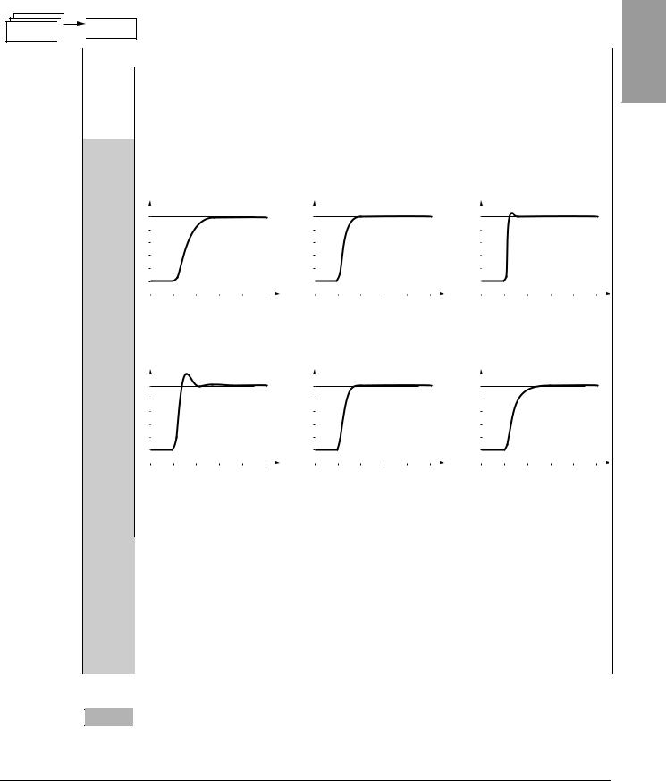
|
VVDED303042NAR6/04 |
Section 3: Menus |
|
06/2004 |
Settings Menu SEt- |
SEt-
|
Code |
Description |
Adjustment Range |
Factory Setting |
||
|
IR compensation or voltage boost |
0 to 100% |
20 |
|||
|
If UFt (page 31) = n or nLd, UFr is IR compensation. |
|||||
|
If UFt = L or P, UFr is voltage boost. |
|||||
|
UFr |
Used to optimize torque at very low speed. Increase UFr if the torque is insufficient.
To avoid operating instability, ensure that the value of UFr is not too high for a warm motor.
NOTE: Modifying UFt (page 31) will cause UFr to return to the factory setting (20%).
|
Frequency loop gain |
1 to 100% |
20 |
|
This parameter can only be accessed if UFt (page 31) = n or nLd.
FLG adjusts the speed ramp based on the inertia of the driven load.
If the value is too low, the response time is longer. If the value is too high, operating instability can result.
|
Hz |
FLG low |
Hz |
FLG correct |
Hz |
FLG high |
||||||||||||
|
50 |
50 |
50 |
|||||||||||||||
|
FLG |
40 |
40 |
|||||||||||||||
|
40 |
|||||||||||||||||
|
30 |
In this case, |
30 |
30 |
In this case, |
|||||||||||||
|
increase FLG |
reduce FLG |
||||||||||||||||
|
20 |
20 |
20 |
|||||||||||||||
|
10 |
10 |
10 |
|||||||||||||||
|
0 |
0 |
0 |
|||||||||||||||
|
-10 |
-10 |
-10 |
|||||||||||||||
|
0 |
0.1 0.2 0.3 0.4 0.5 t |
0 |
0.1 0.2 0.3 0.4 |
0.5 t |
0 |
0.1 0.2 0.3 0.4 0.5 t |
|||||||||||
|
Frequency loop stability |
1 to 100% |
20 |
|||||||||||||||
This parameter can only be accessed if UFt (page 31) = n or nLd.
After a period of acceleration or deceleration, StA adapts the return to a steady state to the dynamics of the machine.
If the value is too low, overspeed or operating instability can result. If the value is too high, the response time is longer.
|
Hz |
StA low |
Hz |
StA correct |
Hz |
StA high |
||||||||||||||||||||||||
|
StA |
50 |
50 |
50 |
||||||||||||||||||||||||||
|
40 |
40 |
40 |
|||||||||||||||||||||||||||
|
In this case, |
In this case, reduce |
||||||||||||||||||||||||||||
|
30 |
30 |
30 |
|||||||||||||||||||||||||||
|
increase StA |
StA |
||||||||||||||||||||||||||||
|
20 |
20 |
20 |
|||||||||||||||||||||||||||
|
10 |
10 |
10 |
|||||||||||||||||||||||||||
|
0 |
0 |
0 |
|||||||||||||||||||||||||||
|
-10 |
-10 |
-10 |
|||||||||||||||||||||||||||
|
0 |
0.1 |
0.2 |
0.3 |
0.4 |
0.5 t |
0 |
0.1 |
0.2 |
0.3 |
0.4 |
0.5 |
t |
0 |
0.1 |
0.2 |
0.3 |
0.4 |
0.5 t |
|||||||||||
|
Slip compensation |
0 to 150% |
100 |
|||||||||||||||||||||||||||
|
This parameter can only be accessed if UFt (page 31) = n or nLd. |
|||||||||||||||||||||||||||||
|
SLP |
SLP adjusts slip compensation for fine tuning of speed regulation. |
||||||||||||||||||||||||||||
|
If the slip setting < actual slip, the motor is not rotating at the correct speed in steady state. |
|||||||||||||||||||||||||||||
|
If the slip setting > actual slip, the motor is overcompensated and the speed is unstable. |
|||||||||||||||||||||||||||||
|
0 to In (In is the |
|||||||||||||||||||||||||||||
|
Level of DC injection braking current activated via a logic input |
nominal drive |
||||||||||||||||||||||||||||
|
IdC |
See page 53. |
controller current |
0.7 In |
||||||||||||||||||||||||||
|
or selected as a stop mode.1 |
|||||||||||||||||||||||||||||
|
indicated on the |
|||||||||||||||||||||||||||||
|
nameplate). |
|||||||||||||||||||||||||||||
|
tdC |
Total DC injection braking time selected as a stop mode.1 |
See page 53. |
0.1 to 30 s |
0.5 s |
|||||||||||||||||||||||||
|
tdC1 |
Automatic DC injection time |
See page 55. |
0.1 to 30 s |
0.5 s |
|||||||||||||||||||||||||
|
SdC1 |
Level of automatic DC injection current |
See page 55. |
0 to 1.2 In |
0.7 In |
|||||||||||||||||||||||||
|
tdC2 |
2nd automatic DC injection time |
See page 55. |
0 to 30 s |
0 s |
|||||||||||||||||||||||||
|
SdC2 |
2nd level of DC injection current |
See page 55. |
0 to 1.2 In |
0.5 In |
1 These settings are not related to the Automatic DC Injection function.
These parameters only appear if the corresponding function has been selected in another menu. To facilitate programming, they can also be accessed and adjusted from the menu where the corresponding function is found. A detailed description of these functions can be found on the indicated pages.
ENGLISH
|
© 2004 Schneider Electric All Rights Reserved |
27 |

ENGLISH
|
Section 3: Menus |
VVDED303042NAR6/04 |
|
Settings Menu SEt- |
06/2004 |
SEt-
|
Code |
Description |
Adjustment Range |
Factory Setting |
||
|
Skip frequency |
0 to 500 |
0 Hz |
|||
|
JPF |
JPF prevents prolonged operation at a frequency range of ± 1 Hz around JPF. This function avoids a critical speed which leads |
||||
|
to resonance. Setting the function to 0 renders it inactive. |
|||||
|
2nd skip frequency |
0 to 500 |
0 Hz |
|||
|
JF2 |
JF2 prevents prolonged operation at a frequency range of ± 1 Hz around JF2. This function avoids a critical speed which leads to |
||||
|
resonance. Setting the function to 0 renders it inactive. |
|||||
|
JGF |
Jog operating frequency |
See page 60. |
0 to 10 Hz |
10 |
Hz |
|
rPG |
PI regulator proportional gain |
See page 68. |
0.01 to 100 |
1 |
|
|
rIG |
PI regulator integral gain |
See page 68. |
0.01 to 100/s |
1/s |
|
|
FbS |
PI feedback multiplication coefficient |
See page 68. |
0.1 to 100 |
1 |
|
|
PIC |
Reversal of the direction of correction of the PI regulator |
See page 68. |
nO — YES |
nO |
|
|
rP2 |
2nd preset PI reference |
See page 68. |
0 to 100% |
30% |
|
|
rP3 |
3rd preset PI reference |
See page 68. |
0 to 100% |
60% |
|
|
rP4 |
4th preset PI reference |
See page 68. |
0 to 100% |
90% |
|
|
SP2 |
2nd preset speed |
See page 59. |
0 to 500 Hz |
10 |
Hz |
|
SP3 |
3rd preset speed |
See page 59. |
0 to 500 Hz |
15 |
Hz |
|
SP4 |
4th preset speed |
See page 59. |
0 to 500 Hz |
20 |
Hz |
|
SP5 |
5th preset speed |
See page 59. |
0 to 500 Hz |
25 |
Hz |
|
SP6 |
6th preset speed |
See page 59. |
0 to 500 Hz |
30 |
Hz |
|
SP7 |
7th preset speed |
See page 59. |
0 to 500 Hz |
35 |
Hz |
|
SP8 |
8th preset speed |
See page 59. |
0 to 500 Hz |
40 |
Hz |
|
SP9 |
9th preset speed |
See page 59. |
0 to 500 Hz |
45 |
Hz |
|
SP10 |
10th preset speed |
See page 59. |
0 to 500 Hz |
50 |
Hz |
|
SP11 |
11th preset speed |
See page 59. |
0 to 500 Hz |
55 |
HZ |
|
SP12 |
12th preset speed |
See page 59. |
0 to 500 Hz |
60 |
Hz |
|
SP13 |
13th preset speed |
See page 59. |
0 to 500 Hz |
70 |
Hz |
|
SP14 |
14th preset speed |
See page 59. |
0 to 500 Hz |
80 |
Hz |
|
SP15 |
15th preset speed |
See page 59. |
0 to 500 Hz |
90 |
Hz |
|
SP16 |
16th preset speed |
See page 59. |
0 to 500 Hz |
100 Hz |
|
|
CLI |
Current limit |
0.25 to 1.5 In1 |
1.5 In |
||
|
Used to limit the torque and the temperature rise of the motor. |
|||||
|
CL2 |
2nd current limit |
See page 73. |
0.25 to 1.5 In |
1.5 In |
|
|
Low speed operating time |
0 to 999.9 s |
0 (no time limit) |
|||
|
tLS |
After operation at LSP for a defined period, a motor stop is requested automatically. The motor restarts if the frequency reference |
||||
|
is greater than LSP and if a run command is still present. |
|||||
|
rSL |
Restart error threshold (wake-up threshold) |
See page 69. |
0 to 100% |
0 |
|
|
UFr2 |
IR compensation, motor 2 |
See page 75. |
0 to 100% |
20 |
|
|
FLG2 |
Frequency loop gain, motor 2 |
See page 75. |
1 to 100% |
20 |
|
|
StA2 |
Stability, motor 2 |
See page 75. |
1 to 100% |
20 |
|
|
SLP2 |
Slip compensation, motor 2 |
See page 75. |
0 to 150% |
100% |
|
1 In is the nominal drive controller current indicated on the drive controller nameplate.
These parameters only appear if the corresponding function has been selected in another menu. To facilitate programming, they can also be accessed and adjusted from the menu where the corresponding function is found. A detailed description of these functions can be found on the indicated pages.
|
28 |
© 2004 Schneider Electric All Rights Reserved |
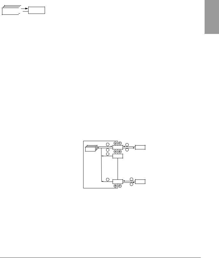
|
VVDED303042NAR6/04 |
Section 3: Menus |
|
06/2004 |
Drive Control Menu drC- |
SEt-
|
Code |
Description |
Adjustment Range |
Factory Setting |
|||
|
Ftd |
Motor frequency threshold above which the relay contact (R1 or R2) closes, |
0 to 500 Hz |
bFr |
|||
|
or output AOV = 10 V. R1, R2, or dO must be assigned to FtA. |
||||||
|
ttd |
Motor thermal state threshold above which the relay contact (R1 or R2) closes, |
0 to 118% |
100% |
|||
|
or output AOV = 10 V. R1, R2, or dO must be assigned to tSA. |
||||||
|
Ctd |
Motor current threshold beyond which the relay contact (R1 or R2) closes, |
0 to 1.5 In1 |
In1 |
|||
|
or output AOV = 10 V. R1, R2, or dO must be assigned to CtA. |
||||||
|
Scale factor for display parameter SPd1/SPd2/SPd3 (see SUPmenu on |
0.1 to 200 |
30 |
||||
|
page 85) |
||||||
|
Used to scale a value (such as motor speed) in proportion to the output frequency rFr. |
||||||
|
If SdS ≤ 1, SPd1 is displayed (possible definition = 0.01). |
||||||
|
If 1 < SdS ≤ 10, SPd2 is displayed (possible definition = 0.1). |
||||||
|
If SdS > 10, SPd3 is displayed (possible definition = 1). |
||||||
|
If SdS > 10 and SdS x rFr > 9999: |
||||||
|
SdS |
SdS x rFr |
|||||
|
Display of Spd3 = |
(to 2 decimal places). |
|||||
|
1000 |
||||||
|
For example, if SdS x rFr equals 24,223, the display shows 24.22. |
||||||
|
If SdS > 10 and SdS x rFr > 65535, the display shows 65.54. |
||||||
|
Example: Display motor speed for a 4-pole motor, |
||||||
|
1500 rpm at 50 Hz (synchronous speed): |
||||||
|
SdS = 30 |
||||||
|
SPd3 = 1500 at rFr = 50 Hz |
||||||
|
SFr |
Switching frequency |
See page 32. |
2.0 to 16 kHz |
4 kHz |
||
|
This parameter can also be accessed in the drCmenu. |
||||||
1 In is the nominal drive controller current indicated on the drive controller nameplate.
DRIVE CONTROL MENU drC-
|
ENT |
ESC |
Standard motor frequency |
|
|
bFr |
|||
|
drC- |
|||
|
ESC |
ENT |
||
|
ESC |
|||
|
tAI |
|||
|
ESC |
ESC |
Return to factory settings/restore |
|
|
FCS |
|||
|
configuration |
|||
|
ENT |
With the exception of tUn, drive control parameters can only be modified when the drive controller is stopped and no run command is present. This menu can be accessed with the access locking switch on the remote keypad display in the 
•Setting the drive control parameters to the values on the motor nameplate
•Performing an auto-tune operation (on a standard asynchronous motor)
ENGLISH
|
© 2004 Schneider Electric All Rights Reserved |
29 |

ENGLISH
|
Section 3: Menus |
VVDED303042NAR6/04 |
|
Drive Control Menu drC- |
06/2004 |
drC-
|
Code |
Description |
Adjustment Range |
Factory Setting |
||||||||
|
bFr |
Motor frequency |
50 or 60 Hz |
50 |
||||||||
|
This parameter modifies the presets of the following parameters: HSP (page 26), Ftd (page 29), FrS (page 30), and tFr |
|||||||||||
|
(page 32). |
|||||||||||
|
Nominal motor voltage indicated on the nameplate |
Varies with drive |
Varies with drive |
|||||||||
|
controller rating |
controller rating |
||||||||||
|
UnS |
ATV31•••M2: 100 to 240 V |
||||||||||
|
ATV31•••M3X: 100 to 240 V |
|||||||||||
|
ATV31•••N4: 100 to 500 V |
|||||||||||
|
ATV31•••S6X: 100 to 600 V |
|||||||||||
|
Nominal motor frequency indicated on the nameplate |
10 to 500 Hz |
50 Hz |
|||||||||
|
The ratio |
UnS (in volts) |
must not exceed the following values: |
|||||||||
|
FrS (in Hz) |
|||||||||||
|
FrS |
ATV31•••M2: 7 |
||||||||||
|
ATV31•••M3X: 7 |
|||||||||||
|
ATV31•••N4: 14 |
|||||||||||
|
ATV31•••S6X: 17 |
|||||||||||
|
NOTE: Changing the setting of bFr to 60 Hz also changes the setting of FrS to 60 Hz. |
|||||||||||
|
nCr |
Nominal motor current indicated on the nameplate |
0.25 to 1.5 In1 |
Varies with drive |
||||||||
|
controller rating |
|||||||||||
|
Nominal motor speed indicated on the nameplate |
0 to 32760 rpm |
Varies with drive |
|||||||||
|
controller rating |
|||||||||||
|
0 to 9999 rpm, then 10.00 to 32.76 krpm |
|||||||||||
|
If the nameplate indicates synchronous speed and slip (in Hz or as a percentage) instead of nominal speed, calculate nominal |
|||||||||||
|
speed as follows: |
|||||||||||
|
Nominal speed = Synchronous speed x |
100 — slip as a% |
||||||||||
|
nSP |
100 |
||||||||||
|
or |
|||||||||||
|
Nominal speed = Synchronous speed x |
50 — slip in Hz |
(50 Hz motors) |
|||||||||
|
50 |
|||||||||||
|
or |
|||||||||||
|
Nominal speed = Synchronous speed x |
60 — slip in Hz |
(60 Hz motors) |
|||||||||
|
60 |
|||||||||||
|
COS |
Motor power factor indicated on the nameplate |
0.5 to 1 |
Varies with drive |
||||||||
|
controller rating |
|||||||||||
1 In is the nominal drive controller current indicated on the drive controller nameplate.
|
30 |
© 2004 Schneider Electric All Rights Reserved |

|
VVDED303042NAR6/04 |
Section 3: Menus |
|
06/2004 |
Drive Control Menu drC- |
drC-
|
Code |
Description |
Adjustment Range |
Factory Setting |
|
|
Cold state stator resistance |
See below. |
nO |
||
nO: Function inactive. For applications that do not require high performance or do not tolerate automatic auto-tuning (passing a current through the motor) each time the drive is powered up.
InIt: Activates the function. Used to improve low-speed performance, whatever the thermal state of the motor.
XXXX: Value of cold state stator resistance used, in mΩ.
|
rSC |
NOTE: We recommended that you activate this function for lifting and handling applications. This function should only |
|
be activated when the motor is cold. |
When rSC = InIt, parameter tUn is forced to POn. At the next run command, the stator resistance is measured with an auto-tune. The value of parameter rSC then changes to this measured stator resistance value (XXXX) and is maintained at that value; tUn remains forced to POn. Parameter rSC remains at InIt as long as the stator resistance measurement has not been performed.
Value XXXX can be forced or modified using the 
|
Motor control auto-tuning |
See below. |
nO |
Before performing an auto-tune, ensure that all the drive control parameters (UnS, FrS, nCr, nSP, COS) are configured correctly. Parameter tUn can be modified with the drive controller running; however, an auto-tune will only be performed if no run or braking command is present.
nO: Auto-tuning is not performed.
YES: Auto-tuning is performed as soon as possible, then the parameter automatically switches to dOnE or, in the event of a fault, to nO. The tnF fault is displayed if tnL = YES (see page 81).
dOnE: Auto-tuning is completed and the measured stator resistance will be used to control the motor. tUn rUn: Auto-tuning is performed each time a run command is sent.
POn: Auto-tuning is performed each time the controller is powered up.
LI1 to LI6: Auto-tuning is performed when the logic input assigned to this function transitions from 0 to 1.
Note:
tUn is forced to POn if rSC is any value other than nO.
Auto-tuning will only be performed if no run or braking command is present. If a freewheel stop or fast stop function is assigned to a logic input, this input must be set to 1 (active at 0). Auto-tuning may last for 1 to 2 seconds. Wait for the display to change to dOnE or nO. Interrupting auto-tuning may result in an auto-tuning fault (see page 88) and cause the motor to be improperly tuned. During auto-tuning, the motor operates at nominal current.
|
Auto-tuning status |
See below. |
tAb |
|
|
(status information only, cannot be modified) |
|||
tAb: The default stator resistance value is used to control the motor. tUS PEnd: Auto-tuning has been requested but not yet performed.
PrOG: Auto-tuning is in progress. FAIL: Auto-tuning has failed.
dOnE: Auto-tuning is complete. The stator resistance measured by the auto-tuning function is used to control the motor. Strd: Auto-tuning is complete. The cold state stator resistance is used to control the motor (rSC must be other than nO).
|
Selection of the voltage/frequency ratio |
See below. |
n |
|
L: Constant torque (for motors connected in parallel or special motors) P: Variable torque (pump and fan applications)
n: Sensorless flux vector control (for constant torque applications)
nLd: Energy savings (for variable torque applications not requiring high dynamics. This behaves in a similar way to the P ratio at no load and the n ratio with load.)
|
Voltage |
||
|
UFt |
UnS |
|
|
L |
||
|
n |
||
|
P |
Frequency |
|
|
FrS |
||
ENGLISH
|
© 2004 Schneider Electric All Rights Reserved |
31 |

ENGLISH
|
Section 3: Menus |
VVDED303042NAR6/04 |
|
Drive Control Menu drC- |
06/2004 |
drC-
|
Code Description |
Adjustment Range |
Factory Setting |
|
|
Random switching frequency |
See below. |
YES |
|
This function randomly modulates the switching frequency to reduce motor noise.
nrd
YES: Frequency with random modulation nO: Fixed frequency
|
Switching frequency1 |
2.0 to 16 kHz |
4 kHz |
|
|
Adjust this setting to reduce audible motor noise. If the switching frequency is set to a value higher than 4 kHz, in the event of |
|||
|
SFr |
excessive temperature rise, the drive controller automatically reduces the switching frequency. It increases it again when the |
||
|
temperature returns to normal. If the switching frequency is set above the factory setting (4 kHz), refer to the ATV31 Installation |
|||
|
Manual for derating curves. |
|||
|
tFr |
Maximum output frequency |
10 to 500 Hz |
60 Hz |
The factory setting is 60 Hz, or 72 Hz if bFr is set to 60 Hz.
|
Suppression of the speed loop filter |
See below. |
nO |
|
nO: The speed loop filter is active (prevents the reference from being exceeded).
YES: The speed loop filter is suppressed. In position control applications, this setting reduces the response time, but the reference may be exceeded.
|
Hz |
Hz |
|||||||||||||
|
50 |
50 |
|||||||||||||
|
SrF |
40 |
40 |
||||||||||||
|
SSL = nO |
SSL = YES |
|||||||||||||
|
30 |
30 |
|||||||||||||
|
20 |
20 |
|||||||||||||
|
10 |
10 |
|||||||||||||
|
0 |
0 |
|||||||||||||
|
-10 |
0,1 |
0,2 |
0,3 |
0,4 |
0,5 |
t |
-10 |
0,1 |
0,2 |
0,3 |
0,4 |
0,5 |
t |
|
|
0 |
0 |
|
Saving the configuration2 |
See below. |
nO |
nO: Function inactive
StrI: Saves the current configuration (but not the result of auto-tuning) to EEPROM. SCS automatically switches to nO as soon as the save is performed. Use this function to keep another configuration in reserve, in addition to the current configuration.
|
SCS |
The drive controller is factory set with the current configuration and the backup configuration both initialized to the factory |
|
configuration. |
If the remote keypad display is connected to the drive controller, up to four additional settings are available: FIL1, FIL2, FIL3, and FIL4. Use these selections to save up to four configurations in the remote keypad display’s EEPROM memory. SCS automatically switches to nO as soon as the save is performed.
|
Return to factory settings/Restore configuration2 |
See below. |
nO |
nO: Function inactive
rECI: Replaces the current configuration with the backup configuration previously saved by SCS (SCS set to Strl). rECI is visible only if the backup configuration has been saved. FCS automatically changes to nO as soon as this action is performed. InI: Replaces the current configuration with the factory settings. FCS automatically switches to nO as soon as this action is performed.
If the remote keypad display is connected to the drive controller, up to four additional selections are available corresponding to FCS backup files loaded in the remote keypad display’s EEPROM memory: FIL1, FIL2, FIL3, and FIL4. These
selections replace the current configuration with the corresponding backup configuration in the remote keypad display. FCS automatically changes to nO as soon as this action is performed.
Note: If nAd briefly appears on the display once the parameter has switched to nO, the configuration transfer is not possible and has not been performed (because the controller ratings are different, for example). If ntr briefly appears on the display once the parameter has switched to nO, a configuration transfer error has occurred and the factory settings must be restored using InI. In both cases, check the configuration to be transferred before trying again.
NOTE: For rECI, InI, and FIL1 to FIL4 to take effect, you must press and hold down the ENT key for 2 s.
1This parameter can also be accessed in the Settings menu, SEt-. See page 25.
2SCS and FCS can be accessed in several configuration menus, but their settings affect all menus and parameters as a whole.
|
32 |
© 2004 Schneider Electric All Rights Reserved |

|
VVDED303042NAR6/04 |
Section 3: Menus |
|
06/2004 |
I/O Menu I-O- |
I/O MENU I-O-
|
ENT |
ESC |
|
|
I-O- |
tCC |
|
|
ESC |
ENT |
|
|
ESC |
||
|
ESC |
ESC |
|
|
FCS |
||
|
ENT |
2-wire/3-wire control
Return to factory settings/restore configuration
I/O parameters can only be modified when the drive controller is stopped and no run command is present. This menu can be accessed with the access locking switch on the remote keypad display in the 
I-O-
|
Code Description |
Factory Setting |
2C
Type of control: 2-wire, 3-wire, or local
ATV31••••••A: LOC
Control configuration: 2C = 2-wire control 3C = 3-wire control
LOC = Local control, for ATV31••••••A controllers only. This option is not available if parameter LAC = L3 (see page 46).
2-wire control (maintained contact): The state of the input (open or closed) controls running or stopping.
|
Wiring example: |
ATV31 Controller |
|
LI1: forward |
24 V LI1 LIx |
|
LIx: reverse |
tCC
3-wire control (pulse control): A forward or reverse pulse is sufficient to control startup. A stop pulse is sufficient to control stopping.
|
ATV31 Controller |
|
|
Wiring example: |
24 V LI1 LI2 LIx |
|
LI1: stop |
|
|
LI2: forward |
|
|
LIx: reverse |
NOTE: To change the assignment of tCC, press the ENT key for 2 s. This causes the following functions to return to their factory setting: rrS, tCt, and all functions affecting logic inputs.
|
Type of 2-wire control (parameter only accessible if tCC = 2C) |
trn |
|
LEL: If the forward or reverse input is high when the drive controller is powered up, the drive controller will start the motor. If both inputs are high on power up, the drive controller will run forward.
tCt trn: The forward or reverse input must transition from low to high before the drive controller will start the motor. If the forward or reverse input is high when the drive controller is powered up, the input must be cycled before the drive controller will start the motor.
PFO: Same as LEL, but the forward input has priority over the reverse input. If forward is activated while the controller is running in reverse, the drive controller will run in the forward direction.
if tCC = 2C: LI2 Reverse operation via logic input if tCC = 3C: LI3
if tCC = LOC: nO
If rrS = nO, reverse operation is not assigned to a logic input. Reverse operation may still be commanded by another means, rrS such as negative voltage on AI2, a serial link command, or the remote keypad.
|
nO: Not assigned |
|
|
LI2: Logic input LI2, can be accessed if tCC = 2C |
LI5: Logic input LI5 |
|
LI3: Logic input LI3 |
LI6: Logic input LI6 |
|
LI4: Logic input LI4 |
ENGLISH
|
© 2004 Schneider Electric All Rights Reserved |
33 |

ENGLISH
|
Section 3: Menus |
VVDED303042NAR6/04 |
|
I/O Menu I-O- |
06/2004 |
I-O-
|
Code |
Description |
Factory Setting |
||||
|
Value for low speed (LSP) on input AI3, can be set between 0 and 20 mA |
4 mA |
|||||
|
Value for high speed (HSP) on input AI3, can be set between 4 and 20 mA |
20 mA |
|||||
|
These two parameters are used to configure the input for 0–20 mA, 4–20 mA, 20–4 mA, etc. |
||||||
|
Frequency |
Frequency |
|||||
|
HSP |
Example: |
HSP |
||||
|
CrL3 |
20–4 mA |
|||||
|
CrH3 |
||||||
|
LSP |
LSP |
|||||
|
0 |
0 |
AI 3 |
||||
|
AI 3 |
CrH3 |
CrL3 |
||||
|
CrL3 |
CrH3 |
20 (mA) |
(4 mA) |
(20 mA) |
(mA) |
|
Configuration of the analog output |
0A |
|
|
AO1t |
0A: 0–20 mA configuration (use terminal AOC) |
|
|
4A: 4–20 mA configuration (use terminal AOC) |
||
|
10U: 0–10 V configuration (use terminal AOV) |
||
|
Analog/logic output AOC/AOV |
nO |
|
nO: Not assigned
OCr: Motor current. 20 mA or 10 V corresponds to twice the nominal drive controller current. rFr: Motor frequency. 20 mA or 10 V corresponds to the maximum frequency tFr (page 32). Otr: Motor torque. 20 mA or 10 V corresponds to twice the nominal motor torque.
OPr: Power supplied by the drive. 20 mA or 10 V corresponds to twice the nominal drive controller power.
Making the following assignments changes the analog output to a logic output (refer to the ATV31 Installation Manual for more information). With these assignments, configure AOt to 0 A.
|
dO |
FLt: Drive fault |
|
|
rUn: Drive running |
||
|
FtA: Frequency threshold reached (Ftd parameter in the SEtmenu, page 29) |
||
|
FLA: High speed (HSP) reached |
||
|
CtA: Current threshold reached (Ctd parameter in the SEtmenu, page 29) |
||
|
SrA: Frequency reference reached |
||
|
tSA: Motor thermal threshold reached (ttd parameter in the SEtmenu, page 29) |
||
|
bLC: Brake sequence (status information only. bLC can be only be activated or deactivated from the FUnmenu, see page 72). |
||
|
APL: Loss of 4–20 mA signal, even if LFL = nO (page 81) |
The logic output state is 1 (24 V) when the selected assignment is active, except for FLt which is in state 1 if the drive controller is not faulted.
nO: Not assigned FLt: Drive fault rUn: Drive running
FtA: Frequency threshold reached (Ftd parameter in the SEtmenu, page 29) FLA: High speed (HSP) reached
r1 CtA: Current threshold reached (Ctd parameter in the SEtmenu, page 29) SrA: Frequency reference reached
tSA: Motor thermal threshold reached (ttd parameter in the SEtmenu, page 29) APL: Loss of 4–20 mA signal, even if LFL = nO (page 81)
The relay is powered up when the selected assignment is active, except for FLt which is powered up if the drive controller is not faulted.
nO: Not assigned FLt: Drive fault rUn: Drive running
FtA: Frequency threshold reached (Ftd parameter in the SEtmenu, page 29) FLA: High speed (HSP) reached
r2 CtA: Current threshold reached (Ctd parameter in the SEtmenu, page 29) SrA: Frequency reference reached
tSA: Motor thermal threshold reached (ttd parameter in the SEtmenu, page 29)
bLC: Brake sequence (status information only. bLC can be only be activated or deactivated from the FUnmenu, see page 72). APL: Loss of 4–20 mA signal, even if LFL = nO (page 81)
The relay is powered up when the selected assignment is active, except for FLt which is powered up if the drive controller is not faulted.
|
34 |
© 2004 Schneider Electric All Rights Reserved |

|
VVDED303042NAR6/04 |
Section 3: Menus |
|
06/2004 |
I/O Menu I-O- |
I-O-
|
Code |
Description |
Factory Setting |
|
|
Saving the configuration1 |
nO |
||
|
nO: Function inactive |
|||
|
StrI: Saves the current configuration (but not the result of auto-tuning) to EEPROM. SCS automatically switches to nO as |
|||
|
soon as the save is performed. Use this function to keep another configuration in reserve, in addition to the current configuration. |
|||
|
SCS |
The drive controller is factory set with the current configuration and the backup configuration both initialized to the factory |
||
|
configuration. |
|||
|
If the remote keypad display is connected to the drive controller, up to four additional settings are available: FIL1, FIL2, |
|||
|
FIL3, and FIL4. Use these selections to save up to four configurations in the remote keypad display’s EEPROM memory. |
|||
|
SCS automatically switches to nO as soon as the save is performed. |
|||
|
Return to factory settings/restore configuration1 |
nO |
||
|
nO: Function inactive |
|||
|
rECI: Replaces the current configuration with the backup configuration previously saved by SCS |
(SCS set to Strl). rECI is |
||
|
visible only if the backup configuration has been saved. FCS automatically changes to nO as soon as this action is performed. |
|||
|
InI: Replaces the current configuration with the factory settings. FCS automatically switches to nO as soon as this action is |
|||
|
performed. |
|||
|
FCS |
If the remote keypad display is connected to the drive controller, up to four additional selections are available corresponding to |
||
|
backup files loaded in the remote keypad display’s EEPROM memory: FIL1, FIL2, FIL3, and FIL4. These |
|||
|
selections replace the current configuration with the corresponding backup configuration in the remote keypad display. FCS |
|||
|
automatically changes to nO as soon as this action is performed. |
|||
|
Note: If nAd briefly appears on the display once the parameter has switched to nO, the configuration transfer is not possible |
|||
|
and has not been performed (because the controller ratings are different, for example). If ntr briefly appears on the display |
|||
|
once the parameter has switched to nO, a configuration transfer error has occurred and the factory settings must be restored |
|||
|
using InI. In both cases, check the configuration to be transferred before trying again. |
|||
|
NOTE: For rECI, InI, and FIL1 to FIL4 to take effect, you must press and hold down the ENT key for 2 s. |
|||
1 SCS and FCS can be accessed in several configuration menus, but their settings affect all menus and parameters as a whole.
ENGLISH
|
© 2004 Schneider Electric All Rights Reserved |
35 |

Section 3: Menus
Control Menu CtL-
CONTROL MENU CTL-
ENGLISH
Control Channels
VVDED303042NAR6/04
06/2004
|
ENT |
ESC |
|
|
CtL- |
LAC |
|
|
ESC |
ENT |
|
|
ESC |
||
|
Fr1 |
||
|
ESC |
ESC |
|
|
FCS |
||
|
ENT |
Function access level
Return to factory settings/restore configuration
Control parameters can only be modified when the drive controller is stopped and no run command is present. This menu can be accessed with the access locking switch on the remote keypad display in the 
Control commands, such as forward and reverse, and speed reference commands can be sent to the drive controller from the sources specified in Table 6. ATV31 drive controllers allow you to assign control and reference sources to separate control channels (Fr1, Fr2, Cd1, or Cd2, see
pages 46–47) and to switch between them. For example, you might assign LCC to reference channel 1 and CAn to reference channel 2 and switch between the two reference sources. It is also possible to use separate sources for control and reference commands. This is called mixed mode operation. These functions are explained in detail in the sections beginning on page 38.
|
Table 6: |
Control and Reference Sources |
||||
|
Control Sources (CMD) |
Reference Sources (rFr) |
||||
|
AI1, |
|||||
|
tEr: |
Terminal (LI) |
AI2, |
Terminal |
||
|
AI3: |
|||||
|
LOC: |
Drive keypad (RUN/STOP) on |
AIP: |
Potentiometer on ATV31••••••A only |
||
|
ATV31••••••A controllers only |
|||||
|
Drive keypad (on ATV31•••••• and |
|||||
|
LCC: |
Remote keypad display (RJ45 socket) |
LCC: |
ATV31••••••A controllers) or remote |
||
|
keypad display |
|||||
|
Mdb: |
Modbus (RJ45 socket) |
Mdb: |
Modbus (RJ45 socket) |
||
|
CAn: |
CANopen (RJ45 socket) |
CAn: |
CANopen (RJ45 socket) |
||

UNINTENDED EQUIPMENT OPERATION
The stop buttons on ATV31••••••A drive controllers and on the remote keypad display can be programmed to not have priority. To retain stop key priority, set PSt to YES (see page 49).
Failure to follow this instruction can result in death, serious injury, or equipment damage.
|
36 |
© 2004 Schneider Electric All Rights Reserved |

|
VVDED303042NAR6/04 |
Section 3: Menus |
|
|
06/2004 |
Control Menu CtL- |
|
|
Parameter LAC |
Use parameter LAC (page 46) in the CtLmenu to select levels of function |
|
|
access and to set the control and reference sources. |
||
|
1. LAC = L1: Level 1—access to standard functions. Control and reference |
||
|
commands come from one source. See “Parameter LAC = L1 or L2” on |
||
|
page 38. |
||
|
2. LAC = L2: Level 2—access to all of the level 1 functions, plus the |
||
|
advanced functions listed below. Control and reference commands |
||
|
come from one source. See “Parameter LAC = L1 or L2” on page 38. |
||
|
— +/- Speed (motorized potentiometer) |
||
|
— |
Brake control |
|
|
— Switching for 2nd current limit |
||
|
— |
Motor switching |
|
|
— Management of limit switches |
3. LAC = L3: Level 3—access to all of the level 2 functions. Control and reference commands can come from separate sources. See “Parameter LAC = L3” on page 39.
ENGLISH
|
© 2004 Schneider Electric All Rights Reserved |
37 |

ENGLISH
|
Section 3: Menus |
VVDED303042NAR6/04 |
|
Control Menu CtL- |
06/2004 |
Parameter LAC = L1 or L2
Legend:
|
A |
A |
C |
||||||||
|
B |
A B |
|||||||||
|
C |
C |
|||||||||
If parameter LAC is set to L1 or L2, the control and reference commands come from one source. The possible control and reference sources, and the settings that specify them, are:
•Control and reference via the input terminals or the drive keypad display in forced local (see FLO on page 82)
•Control and reference via the Modbus serial link
•Control and reference via the CANopen serial link
•Control and reference via the remote keypad display (see LCC on page 48)
NOTE: Modbus or CANopen is selected online by writing the appropriate control word (refer to the protocol-specific documentation).
The diagram below illustrates the order of priority when more than one control and reference source is specified. In the diagram, information flows from left to right. At step 1, LCC is not set to YES to enable the remote keypad display, so the drive keypad display is selected as the control and reference source. At steps 2–4, Modbus, CANopen, and forced local control are not set to YES, so the drive keypad display remains the selected source. The order of priority, therefore, is forced local, CANopen, Modbus, and the drive keypad display or the remote keypad display. For example, if forced local mode were enabled, it would have priority over any other setting. Similarly, if CANopen were enabled, it would have priority over any other setting except for FLO. Refer to the diagrams on pages 41 and 42 for more detail.
The drive keypad display is selected as the control and reference source.
|
Remote Keypad |
FLO |
|
Display |
Forced Local Mode |
•On ATV31•••••• drive controllers with the factory configuration, control and reference commands come from the control terminals.
•On ATV31••••••A drive controllers with the factory configuration, control commands come from the drive keypad display and reference commands come from a summation of the reference potentiometer and AI1 on the control terminals.
•With a remote keypad display, if LCC = YES (see page 48), control and reference commands come from the remote keypad display. The reference frequency is set by parameter LFr in the SEtmenu
(see page 26).
|
38 |
© 2004 Schneider Electric All Rights Reserved |

|
VVDED303042NAR6/04 |
Section 3: Menus |
||||||||||
|
06/2004 |
Control Menu CtL- |
||||||||||
|
Parameter LAC = L3 |
If parameter LAC is set to L3: |
||||||||||
|
• The control and reference channels can be combined (parameter |
|||||||||||
|
CHCF = SIM, see page 47), or |
|||||||||||
|
• The control and reference channels can be separate |
|||||||||||
|
(parameter CHCF = SEP, see page 47) |
|||||||||||
|
Parameter CHCF = SIM |
The following figure illustrates combined control and reference sources: |
||||||||||
|
Selection of reference channel |
|||||||||||
|
1 (Fr1, page 46) |
|||||||||||
|
The control commands are |
Control and reference from |
||||||||||
|
from the same source. |
|||||||||||
|
Fr1 |
|||||||||||
|
rFC |
|||||||||||
|
Selection of reference channel |
|||||||||||
|
2 (Fr2, page 46) |
|||||||||||
|
The control commands are |
|||||||||||
|
from the same source. |
|||||||||||
Use parameter rFC (page 47) to select reference channel Fr1 or Fr2, or to configure a logic input or a control word bit for remote switching between the two channels. Refer to the diagram on page 44.
ENGLISH
|
© 2004 Schneider Electric All Rights Reserved |
39 |

Section 3: Menus
Control Menu CtL-
Parameter CHCF = SEP
ENGLISH
VVDED303042NAR6/04
06/2004
The following figures illustrate separate control and reference channels (parameter CHCF = SEP).
Separate Reference Channels:
Selection of reference channel 1 (Fr1, page 46)
Reference from Fr1
|
rFC |
||||
|
Selection of reference channel |
||||
|
2 (Fr2, page 46) |
||||
Use parameter rFC (page 47) to select reference channel Fr1 or Fr2, or to configure a logic input or a control word bit for remote switching between the two channels.
Separate Control Channels:
Selection of control channel 1 (Cd1, page 47).
Control from Cd1
|
CCS |
||||
|
Selection of control channel 2 |
||||
|
(Cd2, page 47) |
||||
Use parameter CCS (page 48) to select control channel Cd1 or Cd2, or to configure a logic input or a control word bit for remote switching between the two channels.
|
40 |
© 2004 Schneider Electric All Rights Reserved |

|
VVDED303042NAR6/04 |
||||
|
06/2004 |
||||
|
Reference Channel for LAC = L1 or |
L2 |
|||
|
Fr1 |
||||
|
+ |
||||
|
UPdt |
speed |
|||
|
— |
||||
|
UPdH |
speed |
|||
|
AI1 |
||||
|
AI2 |
||||
|
AI3 |
||||
|
AIP |
Preset speeds |
|||
|
nO |
||||
|
SA2 |
||||
|
(SP1) |
||||
|
nO |
SP2 |
|||
|
AI1 |
||||
|
AI2 |
SP16 |
|||
|
AI3 |
||||
|
AIP |
LI |
|||
|
PI not assigned |
||||
|
SA3 |
nO |
|||
|
nO |
PI assigned |
|||
|
AI1 |
||||
|
AI2 |
A |
|||
|
AI3 |
PIF |
PI function |
||
|
AIP |
nO |
(see page 64) |
||
|
AI1 |
||||
|
AI2 |
||||
|
AI3 |
||||
|
Fr2 |
||||
|
+ |
||||
|
UPdt |
speed |
B |
||
|
— |
||||
|
UPdH |
||||
|
speed |
||||
|
nO |
||||
|
AI1 |
||||
|
AI2 |
||||
|
AI3 |
||||
|
AIP |
Section 3: Menus
Control Menu CtL-
ENGLISH
Note: If the +/- speed command is configured (Fr1 = UPdt or UPdH), summing inputs SA2/SA3 are not active.
LFr
Remote keypad display
LI
Jog operation
PIF
|
1 |
YES |
|||
|
Channel |
HSP |
ACC DEC |
||
|
Ramps |
||||
|
nO |
nO |
FrH |
rFr |
|
|
2 |
nO |
|||
|
LSP |
AC2 DE2 |
|||
|
Channel |
Modbus |
|||
|
Forced local mode |
||||
|
LCC |
||||
|
FLO |
||||
|
rFC |
||||
|
CANopen |
Modbus or CANopen is selected online by writing the appropriate control word (see the protocol-specific documentation).
Legend:
Function accessible if LAC = L2
A
BA The black square represents
Cthe factory setting of parameter xxx.
|
© 2004 Schneider Electric All Rights Reserved |
41 |

ENGLISH
|
Section 3: Menus |
VVDED303042NAR6/04 |
|
Control Menu CtL- |
06/2004 |
|
Control Channel for LAC = L1 or L2 |
The settings of parameters FLO, LCC, and the selection of Modbus or |
|
CANopen protocol determine both the reference and control channels. The |
|
|
order of priority is FLO, CANopen, Modbus, and LCC. |
|
tCC |
|||||||||||||||||||||||||||||||||||
|
LI |
2C |
LI |
|||||||||||||||||||||||||||||||||
|
LCC |
|||||||||||||||||||||||||||||||||||
|
LI |
3C |
nO |
|||||||||||||||||||||||||||||||||
|
LOC |
FLO |
||||||||||||||||||||||||||||||||||
|
YES |
nO |
CMD ReverseForward |
|||||||||||||||||||||||||||||||||
|
STOP |
|||||||||||||||||||||||||||||||||||
|
Modbus |
|||||||||||||||||||||||||||||||||||
|
CANopen |
|||||||||||||||||||||||||||||||||||
|
RUN |
|||||||||||||||||||||||||||||||||||
|
RUN |
|||||||||||||||||||||||||||||||||||
|
STOP |
|||||||||||||||||||||||||||||||||||
|
STOP |
|||||||||||||||||||||||||||||||||||
|
FWD / REV |
|||||||||||||||||||||||||||||||||||
|
ATV31••••••A |
|||||||||||||||||||||||||||||||||||
|
drive keypad |
Remote keypad |
ATV31••••••A |
|||||||||||||||||||||||||||||||||
|
display |
|||||||||||||||||||||||||||||||||||
|
drive keypad |
|||||||||||||||||||||||||||||||||||
|
STOP |
nO |
||||||||||||||||||||||||||||||||||
|
Legend: |
YES |
||||||||||||||||||||||||||||||||||
|
PSt |
|||||||||||||||||||||||||||||||||||
|
STOP |
|||||||||||||||||||||||||||||||||||
|
(STOP priority) |
|||||||||||||||||||||||||||||||||||
|
XXX |
|||||||||||||||||||||||||||||||||||
|
Remote keypad display |
|||||||||||||||||||||||||||||||||||
|
A |
A The black square represents |
||||||||||||||||||||||||||||||||||
|
B |
|||||||||||||||||||||||||||||||||||
|
C |
the factory setting of parameter xxx. |
||||||||||||||||||||||||||||||||||
|
42 |
© 2004 Schneider Electric All Rights Reserved |

|
VVDED303042NAR6/04 |
Section 3: Menus |
|
06/2004 |
Control Menu CtL- |
|
Reference Channel for LAC = L3 |
ENGLISH |
||||||
|
Fr1 |
|||||||
|
+ |
Note: If the +/- speed command is configured (Fr1 = UPdt or |
||||||
|
UPdH), summing inputs SA2/SA3 are not active. |
|||||||
|
UPdt |
speed |
||||||
|
— |
|||||||
|
UPdH |
|||||||
|
speed |
|||||||
|
FLOC |
|||||||
|
AI1 |
AI1 |
||||||
|
AI2 |
|||||||
|
AI2 |
|||||||
|
AI3 |
|||||||
|
Preset speeds |
AI3 |
||||||
|
LFr |
AIP |
||||||
|
LFr |
|||||||
|
LCC |
nO |
AIP |
|||||
|
LCC |
|||||||
|
Mdb |
|||||||
|
Remote |
(SP1) |
||||||
|
CAn |
Remote |
||||||
|
keypad |
SP2 |
||||||
|
display |
keypad |
||||||
|
display |
|||||||
|
SP16 |
LI |
||||||
|
SA2 |
|||||||
|
Jog |
|||||||
|
nO |
operation |
||||||
|
LI |
|||||||
|
AI1 |
|||||||
|
Mdb |
|||||||
|
AI2 |
PI not assigned PIF |
||||||
|
CAn |
|||||||
|
AI3 |
nO |
||||||
|
LFr |
AIP |
||||||
|
PI assigned |
|||||||
|
LCC |
1 |
||||||
|
Mdb |
|||||||
|
Channel |
HSP |
ACC DEC |
|||||
|
Remote |
CAn |
LI |
Ramps |
||||
|
keypad |
|||||||
|
display |
FrH |
rFr |
|||||
|
SA3 |
nO |
nO |
|||||
|
LSP |
AC2 DE2 |
||||||
|
nO |
|||||||
|
FLO |
|||||||
|
AI1 |
rFC |
Forced local mode |
|||||
|
AI2 |
|||||||
|
LFr |
AI3 |
||||||
|
AIP |
A |
2 |
|||||
|
Mdb |
PIF |
PI function |
Channel |
||||
|
LCC |
nO |
||||||
|
(see page 64) |
|||||||
|
Remote |
CAn |
AI1 |
|||||
|
keypad |
AI2 |
||||||
|
display |
|||||||
|
Fr2 |
AI3 |
||||||
|
+ |
|||||||
|
UPdt |
speed |
B |
|||||
|
— |
|||||||
|
UPdH |
|||||||
|
speed |
|
nO |
Legend: |
|||||||||||||||||||
|
AI1 |
||||||||||||||||||||
|
AI2 |
XXX |
|||||||||||||||||||
|
A |
||||||||||||||||||||
|
AI3 |
A |
The black square represents |
||||||||||||||||||
|
LFr |
AIP |
B |
the factory setting of parameter xxx. |
|||||||||||||||||
|
C |
||||||||||||||||||||
|
LCC |
||||||||||||||||||||
|
Mdb |
||||||||||||||||||||
|
Remote |
||||||||||||||||||||
|
CAn |
||||||||||||||||||||
|
keypad |
||||||||||||||||||||
|
display |
|
© 2004 Schneider Electric All Rights Reserved |
43 |

ENGLISH
|
Section 3: Menus |
VVDED303042NAR6/04 |
|
Control Menu CtL- |
06/2004 |
|
Control Channel for LAC = L3: |
If CHCF is set to SIM (see page 47), parameters Fr1, Fr2, FLO, and FLOC |
|
CHCF = SIM, Combined Reference and |
determine both the reference and control source. For example, if the |
|
Control |
reference is via the analog input on the terminal block, control is via the logic |
|
input on the terminal block. |
LI
ATV31•••A drive keypad
RUN
STOP
RUN / STOP FWD / REV
Remote keypad display
LI
ATV31•••A drive keypad
RUN
STOP
RUN / STOP
FWD / REV
Remote keypad display
|
Fr1 |
|||||||||||||||||||||||||||||||||||||||||||||
|
FLOC |
|||||||||||||||||||||||||||||||||||||||||||||
|
LI |
AI1 |
||||||||||||||||||||||||||||||||||||||||||||
|
UPdt |
ATV31•••A |
AI2 |
|||||||||||||||||||||||||||||||||||||||||||
|
UPdH |
drive keypad |
AI3 |
|||||||||||||||||||||||||||||||||||||||||||
|
AIP |
|||||||||||||||||||||||||||||||||||||||||||||
|
AI1 |
(RUN / STOP) |
||||||||||||||||||||||||||||||||||||||||||||
|
AI2 |
LCC |
||||||||||||||||||||||||||||||||||||||||||||
|
AI3 |
(RUN / STOP |
||||||||||||||||||||||||||||||||||||||||||||
|
AIP |
|||||||||||||||||||||||||||||||||||||||||||||
|
FWD / REV |
|||||||||||||||||||||||||||||||||||||||||||||
|
LCC |
Remote keypad |
||||||||||||||||||||||||||||||||||||||||||||
|
Mdb |
display |
||||||||||||||||||||||||||||||||||||||||||||
|
CAn |
LI |
Forced local |
|||||||||||||||||||||||||||||||||||||||||||
|
FLO |
|||||||||||||||||||||||||||||||||||||||||||||
|
CHCF |
mode |
||||||||||||||||||||||||||||||||||||||||||||
|
rFC |
SEP |
||||||||||||||||||||||||||||||||||||||||||||
|
nO |
|||||||||||||||||||||||||||||||||||||||||||||
|
SIM |
ATV31•••A |
CMD |
|||||||||||||||||||||||||||||||||||||||||||
|
drive keypad |
|||||||||||||||||||||||||||||||||||||||||||||
|
STOP |
nO |
||||||||||||||||||||||||||||||||||||||||||||
|
YES |
|||||||||||||||||||||||||||||||||||||||||||||
|
Fr2 |
STOP |
||||||||||||||||||||||||||||||||||||||||||||
|
PSt |
|||||||||||||||||||||||||||||||||||||||||||||
|
UPdt |
(STOP has priority) |
||||||||||||||||||||||||||||||||||||||||||||
|
Remote keypad |
|||||||||||||||||||||||||||||||||||||||||||||
|
UPdH |
|||||||||||||||||||||||||||||||||||||||||||||
|
display |
|||||||||||||||||||||||||||||||||||||||||||||
|
nO |
|||||||||||||||||||||||||||||||||||||||||||||
|
AI1 |
|||||||||||||||||||||||||||||||||||||||||||||
|
AI2 |
|||||||||||||||||||||||||||||||||||||||||||||
|
AI3 |
|||||||||||||||||||||||||||||||||||||||||||||
|
AIP |
|||||||||||||||||||||||||||||||||||||||||||||
|
LCC |
|||||||||||||||||||||||||||||||||||||||||||||
|
Mdb |
|||||||||||||||||||||||||||||||||||||||||||||
|
CAn |
|||||||||||||||||||||||||||||||||||||||||||||
|
Legend: |
|||||||||||||||||||||||||||||||||||||||||||||
|
XXX |
|||||||||||||||||||||||||||||||||||||||||||||
|
A |
A |
The black square represents |
|||||||||||||||||||||||||||||||||||||||||||
|
B |
|||||||||||||||||||||||||||||||||||||||||||||
|
the factory setting of parameter xxx. |
|||||||||||||||||||||||||||||||||||||||||||||
|
C |
|||||||||||||||||||||||||||||||||||||||||||||
|
44 |
© 2004 Schneider Electric All Rights Reserved |

|
VVDED303042NAR6/04 |
Section 3: Menus |
|
06/2004 |
Control Menu CtL- |
|
Control Channel for LAC = L3: |
Parameters FLO and FLOC are common to reference and control. For |
|
CHCF = SEP, Mixed Mode (Separate |
example, if the reference in forced local mode is via the analog input on the |
|
Reference and Control) |
terminal block, control in forced local mode is via the logic input on the |
|
terminal block. |
LI
ATV31•••A drive keypad
RUN
STOP
RUN / STOP
FWD / REV
Remote keypad display
LI
ATV31•••A drive keypad
RUN
STOP
RUN / STOP
FWD / REV
Remote keypad display
Cd1
tEr
LOC
LCC
Mdb
CAn
LI
CCS
Cd2
tEr
LOC
LCC
Mdb
CAn
|
FLOC |
||||||||||||||||||||||||||||||
|
LI |
AI1 |
|||||||||||||||||||||||||||||
|
ATV31•••A |
AI2 |
|||||||||||||||||||||||||||||
|
AI3 |
||||||||||||||||||||||||||||||
|
drive keypad |
||||||||||||||||||||||||||||||
|
(RUN / STOP) |
AIP |
|||||||||||||||||||||||||||||
|
(RUN / STOP |
LCC |
|||||||||||||||||||||||||||||
|
FWD / REV) |
||||||||||||||||||||||||||||||
|
Remote keypad |
||||||||||||||||||||||||||||||
|
display |
||||||||||||||||||||||||||||||
|
LI |
||||||||||||||||||||||||||||||
|
Forced local mode |
||||||||||||||||||||||||||||||
|
FLO |
||||||||||||||||||||||||||||||
|
CHCF |
||||||||||||||||||||||||||||||
|
SEP |
||||||||||||||||||||||||||||||
|
SIM |
ATV31•••A |
nO |
CMD Forward |
|||||||||||||||||||||||||||
|
drive keypad |
Reverse |
|||||||||||||||||||||||||||||
|
STOP |
||||||||||||||||||||||||||||||
|
STOP |
||||||||||||||||||||||||||||||
|
nO |
||||||||||||||||||||||||||||||
|
STOP |
YES |
|||||||||||||||||||||||||||||
|
PSt |
||||||||||||||||||||||||||||||
|
(STOP has priority) |
||||||||||||||||||||||||||||||
|
Remote keypad |
||||||||||||||||||||||||||||||
|
display |
Legend:
XXX
|
A |
A The black square represents |
||||
|
B |
|||||
|
C |
the factory setting of parameter xxx. |
||||
ENGLISH
|
© 2004 Schneider Electric All Rights Reserved |
45 |

ENGLISH
|
Section 3: Menus |
VVDED303042NAR6/04 |
|
Control Menu CtL- |
06/2004 |
Refer to the function compatibility table on page 21. It is not possible to configure incompatible control functions. The first function configured will prevent any functions that are incompatible with it from being configured.
CtL-
|
Code |
Description |
Adjustment Range |
Factory Setting |
||
|
Function access level |
See below. |
L1 |
|||
|
L1: Level 1—access to standard functions. |
|||||
|
L2: Level 2—access to the level 1 functions plus the following advanced functions in the FUnmenu: |
|||||
|
• |
+/- speed |
||||
|
• |
Brake control |
||||
|
• Switching for second current limit |
|||||
|
• |
Motor switching |
||||
|
LAC |
• Management of limit switches |
||||
|
L3: Level 3—access to all of the level 2 functions plus mixed mode operation. |
|||||
|
Assigning L3 to LAC restores parameters Fr1 (below), Cd1 (page 47), CHCF (page 47), and tCC (page 33) to their factory |
|||||
|
settings (on ATV31••••••A drive controllers, tCC is reset to 2C). |
|||||
|
If LAC is set to L3, you must restore the factory setting with parameter FCS (page 49) to set LAC back to L1 or to change it to L2. |
|||||
|
If LAC is set to L2, you must restore the factory setting with parameter FCS to set LAC back to L1. |
|||||
|
If LAC is set to L2, you can change LAC to L3 without using parameter FCS. |
|||||
|
NOTE: In order to change the assignment of LAC, you must press and hold down the ENT key for 2 seconds. |
|||||
|
Configuration of reference 1 |
See below. |
AI1 |
|||
|
AIP for ATV31••••••A |
|||||
|
AI1: Analog input AI1 |
|||||
|
AI2: Analog input AI2 |
|||||
|
AI3: Analog input AI3 |
|||||
|
AIP: Potentiometer (ATV31••••••A) |
|||||
|
If LAC = L2 or L3, the following additional assignments are possible: |
|||||
|
Fr1 |
UPdt: + speed/- speed via LI1 |
||||
|
UpdH: + speed/- speed via |
r r on the drive keypad display (ATV31 or ATV31••••••A) or on the remote keypad display. For |
||||
|
operation, display the frequency rFr (see page 85).1 |
|||||
|
If LAC = L3, the following additional assignments are possible: |
|||||
|
LCC: Reference via the remote keypad display, LFr parameter in the SEtmenu page 26. |
|||||
|
Ndb: Reference via Modbus |
|||||
|
CAn: Reference via CANopen |
|||||
|
Configuration of reference 2 |
See below. |
nO |
|||
|
nO: Not assigned |
|||||
|
AI1: Analog input AI1 |
|||||
|
AI2: Analog input AI2 |
|||||
|
AI3: Analog input AI3 |
|||||
|
AIP: Potentiometer (ATV31••••••A only) |
|||||
|
If LAC = L2 or L3, the following additional assignments are possible: |
|||||
|
Fr2 |
UPdt: + speed/- speed via LI1 |
||||
|
UpdH:+ speed/- speed via |
r r on the drive keypad display (ATV31 or ATV31••••••A) or on the remote keypad display. For |
||||
|
operation, display the frequency rFr (see page 85).1 |
|||||
|
If LAC = L3, the following additional assignments are possible: |
|||||
|
LCC: Reference via the remote keypad display, LFr parameter in the SEtmenu page 26. |
|||||
|
Ndb: Reference via Modbus |
|||||
|
CAn: Reference via CANopen |
|||||
1 Only one of the UPdt/UPdH assignments is permitted on each reference channel.
|
46 |
© 2004 Schneider Electric All Rights Reserved |

|
VVDED303042NAR6/04 |
Section 3: Menus |
|
06/2004 |
Control Menu CtL- |
CtL-
|
Code |
Description |
Adjustment Range |
Factory Setting |
|
|
Reference switching |
See below. |
Fr1 |
||
|
Use parameter rFC to select channel Fr1 or Fr2, or to configure a logic input or a control bit for remote switching of Fr1 or Fr2. |
||||
|
Fr1: Reference = Reference 1 |
||||
|
Fr2: Reference = Reference 2 |
||||
|
LI1: Logic input LI1 |
||||
|
LI2: Logic input LI2 |
||||
|
LI3: Logic input LI3 |
||||
|
LI4: Logic input LI4 |
||||
|
LI5: Logic input LI5 |
||||
|
LI6: Logic input LI6 |
||||
|
If LAC = L3, the following additional assignments are possible: |
||||
|
rFC |
C111: Bit 11 of the Modbus control word |
|||
|
C112: Bit 12 of the Modbus control word |
||||
|
C113: Bit 13 of the Modbus control word |
||||
|
C114: Bit 14 of the Modbus control word |
||||
|
C115: Bit 15 of the Modbus control word |
||||
|
C211: Bit 11 of the CANopen control word |
||||
|
C212: Bit 12 of the CANopen control word |
||||
|
C213: Bit 13 of the CANopen control word |
||||
|
C214: Bit 14 of the CANopen control word |
||||
|
C215: Bit 15 of the CANopen control word |
||||
|
The reference can be switched with the drive controller running. |
||||
|
Fr1 is active when the logic input or control word bit is in state 0. |
||||
|
Fr2 is active when the logic input or control word bit is in state 1. |
||||
|
Mixed mode (separate control and reference channels) |
See below. |
SIM |
||
|
CHCF |
CHCF can be accessed if LAC = L3. |
|||
|
SIN: Combined control and reference channels |
||||
|
SEP: Separate control and reference channels |
||||
|
tEr |
||||
|
Configuration of control channel 1 |
See below. |
LOC for |
||
|
ATV31••••••A |
||||
|
Cd1 can be accessed if CHCF = SEP and LAC = L3. |
||||
|
Cd1 |
tEr: Terminal block control |
|||
|
LOC: Drive keypad display control (ATV31••••••A only) |
||||
|
LCC: Remote keypad display control |
||||
|
Ndb: Control via Modbus |
||||
|
CAn: Control via CANopen |
||||
|
Configuration of control channel 2 |
See below. |
Mdb: |
||
|
Cd2 can be accessed if CHCF = SEP and LAC = L3. |
||||
|
Cd2 |
tEr: Terminal block control |
|||
|
LOC: Drive keypad display control (ATV31••••••A only) |
||||
|
LCC: Remote keypad display control |
||||
|
Ndb: Control via Modbus |
||||
|
CAn: Control via CANopen |
||||
|
These parameters only appear if the function has been enabled. |
||||
ENGLISH
|
© 2004 Schneider Electric All Rights Reserved |
47 |

ENGLISH
|
Section 3: Menus |
VVDED303042NAR6/04 |
|
Control Menu CtL- |
06/2004 |
CtL-
|
Code |
Description |
Adjustment Range |
Factory Setting |
|
|
Control channel switching |
See below. |
Cd1 |
||
|
CCS can be accessed if CHCF = SEP and LAC = L3. Use parameter CCS to select channel Cd1 or Cd2, or to configure a logic |
||||
|
input or a control bit for remote switching of Cd1 or Cd2. |
||||
|
Cd1: Control channel = Channel 1 |
||||
|
Cd2: Control channel = Channel 2 |
||||
|
LI1: Logic input LI1 |
||||
|
LI2: Logic input LI2 |
||||
|
LI3: Logic input LI3 |
||||
|
LI4: Logic input LI4 |
||||
|
LI5: Logic input LI5 |
||||
|
LI6: Logic input LI6 |
||||
|
CCS |
C111: Bit 11 of the Modbus control word |
|||
|
C112: Bit 12 of the Modbus control word |
||||
|
C113: Bit 13 of the Modbus control word |
||||
|
C114: Bit 14 of the Modbus control word |
||||
|
C115: Bit 15 of the Modbus control word |
||||
|
C211: Bit 11 of the CANopen control word |
||||
|
C212: Bit 12 of the CANopen control word |
||||
|
C213: Bit 13 of the CANopen control word |
||||
|
C214: Bit 14 of the CANopen control word |
||||
|
C215: Bit 15 of the CANopen control word |
||||
|
Channel 1 is active when the input or control word bit is in state 0. |
||||
|
Channel 2 is active when the input or control word bit is in state 1. |
||||
|
Copy channel 1 to channel 2. (The copy is possible only in this direction.) |
See below. |
nO |
||
|
COP can be accessed if LAC = L3. |
||||
|
nO: No copy |
||||
|
SP: Copy reference |
||||
|
Cd: Copy control |
||||
|
COp |
ALL: Copy control and reference |
|||
|
If channel 2 is controlled via the terminal block, channel 1 control is not copied. |
||||
|
If channel 2 reference is set via AI1, AI2, AI3, or AIP, channel 1 reference is not copied. |
||||
|
The reference copied is FrH (before the ramp) unless the channel 2 reference is set via +/- speed. In this case, the reference |
||||
|
copied is rFr (after ramp). |
||||
|
NOTE: Copying the control and/or the reference may change the direction of rotation. |
||||
|
Control via the remote keypad display |
See below. |
nO |
||
|
LCC can only be accessed if the drive controller is equipped with a remote keypad display, and if LAC = L1 or L2. |
||||
|
nO: Function inactive |
||||
|
LCC |
YES: Enables control of the drive controller with the STOP/RESET, RUN, and FWD/REV buttons on the remote keypad |
|||
|
display. The speed reference is given by parameter LFr in the SEtmenu. Only the freewheel, fast stop, and DC injection stop |
||||
|
commands remain active on the terminal block. |
||||
|
If the remote keypad display is not connected, the drive controller will lock on an SLF fault. |
||||
|
These parameters only appear if the function has been enabled. |
||||
|
48 |
© 2004 Schneider Electric All Rights Reserved |

|
VVDED303042NAR6/04 |
Section 3: Menus |
|
06/2004 |
Control Menu CtL- |
CtL-
|
Code Description |
Adjustment Range |
Factory Setting |
|
|
Stop priority |
See below. |
YES |
|
PSt gives priority to the STOP key on the drive keypad display (ATV31••••••A only) or on the remote keypad display, regardless of the control channel selected (terminal block or communication bus). If set to nO, the active control channel has priority. If the active control channel is the local or remote keypad display, the stop button retains priority, regardless of the setting of PSt.
NOTE: To change the assignment of PSt, you must press and hold down the ENT key for 2 seconds
nO: Function inactive YES: STOP key priority
DISABLED STOP COMMAND
Disabling the stop key on the drive keypad display or the remote keypad display will prevent the drive controller from stopping when the stop key is pressed. An external stop command must be installed to stop the motor.
Failure to follow this instruction can result in death, serious injury, or equipment damage.
|
Direction of operation |
See below. |
dFr |
|
Direction of operation allowed for the RUN key on the drive keypad display (ATV31••••••A only).
|
rOt |
dFr: Forward |
||
|
drS: Reverse |
|||
|
bOt: On ATV31•••••• drive controllers, both directions are authorized; on ATV31••••••A controllers, only the forward direction is |
|||
|
possible. |
|||
|
Saving the configuration1 |
See below. |
See below. |
|
|
nO: Function inactive |
|||
|
StrI: Saves the current configuration (but not the result of auto-tuning) to EEPROM. SCS automatically switches to nO as |
|||
|
soon as the save is performed. Use this function to keep another configuration in reserve, in addition to the current configuration. |
|||
|
SCS |
The drive controller is factory set with the current configuration and the backup configuration both initialized to the factory |
||
|
configuration. |
If the remote keypad display is connected to the drive controller, up to four additional settings are available: FIL1, FIL2, FIL3, and FIL4. Use these selections to save up to four configurations in the remote keypad display’s EEPROM memory. SCS automatically switches to nO as soon as the save is performed.
|
Return to factory settings/Restore configuration1 |
See below. |
See below. |
nO: Function inactive
rECI: Replaces the current configuration with the backup configuration previously saved by SCS (SCS set to Strl). rECI is visible only if the backup configuration has been saved. FCS automatically changes to nO as soon as this action is performed. InI: Replaces the current configuration with the factory settings. FCS automatically switches to nO as soon as this action is performed.
If the remote keypad display is connected to the drive controller, up to four additional selections are available corresponding to FCS backup files loaded in the remote keypad display’s EEPROM memory: FIL1, FIL2, FIL3, and FIL4. These
selections replace the current configuration with the corresponding backup configuration in the remote keypad display. FCS automatically changes to nO as soon as this action is performed.
Note: If nAd briefly appears on the display once the parameter has switched to nO, the configuration transfer is not possible and has not been performed (because the controller ratings are different, for example). If ntr briefly appears on the display once the parameter has switched to nO, a configuration transfer error has occurred and the factory settings must be restored using InI. In both cases, check the configuration to be transferred before trying again.
NOTE: For rECI, InI, and FIL1 to FIL4 to take effect, you must press and hold down the ENT key for 2 s.
1 SCS and FCS can be accessed in several configuration menus, but their settings affect all menus and parameters as a whole.
ENGLISH
|
© 2004 Schneider Electric All Rights Reserved |
49 |

|
Section 3: Menus |
VVDED303042NAR6/04 |
|
Application Functions Menu FUn- |
06/2004 |
APPLICATION FUNCTIONS MENU FUN-
ENGLISH
|
ENT |
ENT |
|
|
FUn- |
rPC- |
|
|
ESC |
ESC |
|
|
ENT |
||
|
ESC |
||
|
SA1- |
||
|
ESC |
||
|
ESC |
ENT |
|
|
FCS |
||
|
ESC |
ENT
Sub-menu
ESC
ENT
Sub-menu
ESC
Application function parameters can only be modified when the drive controller is stopped and with no run command present. On the remote keypad display, this menu can be accessed with the access locking switch in the 
Some functions in this menu have numerous parameters. To simplify programming and to minimize scrolling, these functions are grouped into sub-menus. Like menus, sub-menus are identified by a dash. For example, LIAis a sub-menu, but LIn is a parameter.
It is not possible to configure incompatible application functions. The first function configured will prevent any functions that are incompatible with it from being configured. Refer to the function compatibility table on page 21.
|
50 |
© 2004 Schneider Electric All Rights Reserved |
24-25 мая 2023 года
Технополис Москва, м. Текстильщики
Технологическая независимость
в новых реалиях
Инновационный
Саммит 2023
Компания образована в результате продажи бизнеса Schneider Electric в РФ и Беларуси локальному руководству
Добро пожаловать на сайт российской производственной компании Систэм Электрик
Узнавайте первыми о запусках новинок!
SystemeOne — экосистема решений
для энергетики, промышленности и IT
Вертикальная технологическая компания с единой экосистемой на базе российского программного обеспечения.
Кто мы
Мы производим и поставляем оборудование и комплексные решения для проектов по передаче и распределению электроэнергии.
Мы интегрируем лучшие технологии в области управления электроэнергией, автоматизации в режиме реального времени, услуг и решений для объектов гражданского и жилищного строительства, центров обработки данных, инфраструктуры и промышленности.
В Группу компаний Систэм Электрик входят заводы «Потенциал» (г. Козьмодемьянск), Завод ЭлектроМоноблок («СЭЗЭМ», г. Коммунар), НТЦ «Механотроника» (г. Санкт-Петербург), Инженерно-Сервисный Центр (г. Москва) и Центр Инноваций (г. Иннополис). Компания образована в 2022 году в результате продажи бизнеса Schneider Electric в РФ и Беларуси локальному руководству.
Работая под слоганом «Энергия. Технологии. Надежность» Систэм Электрик делает процессы и энергосистемы безопасными, эффективными и технологичными.
О компании в цифрах
Крупнейший в отрасли инженерно-сервисный центр
Локальное производство и сервис
Региональных логистических центра
Офисов в крупнейших городах России и Беларуси
«Опираясь на сплоченную команду профессионалов, мы продолжим поддерживать высокий уровень качества выпускаемой продукции и предоставляемых услуг. Мы с уверенностью смотрим в будущее и видим перспективы для развития и дальнейшего роста компании на российском рынке. Наступило время вызовов и вместе с тем больших возможностей»
Продукция Систэм Электрик
Форум РадиоКот • Просмотр темы — частотник Altivar 31 (atv31hu15m2)
Сообщения без ответов | Активные темы
| ПРЯМО СЕЙЧАС: |
| Автор | Сообщение | ||
|---|---|---|---|
|
|
Заголовок сообщения: частотник Altivar 31 (atv31hu15m2)
|
||
Зарегистрирован: Чт дек 16, 2010 08:28:29 Рейтинг сообщения: 0
|
Нужна помощь в опознании микры , как я полагаю драйвер выходных транзисторов . Фото прилагается. Частотник — atv31hu15m2 И вопрос, почему такое могло произойти, возможен ли вариант , что заменой этой микры все и обойдется, или же это только следствие? Последний раз редактировалось ANGELJT Пн июн 03, 2019 07:26:32, всего редактировалось 1 раз. |
||
| Вернуться наверх |
Профиль
|
||
| Реклама | |
|
|
|
|
korob |
Заголовок сообщения: Re: частотник Altivar 31 (atv31hu15m2)
|
||
Карма: 142 Рейтинг сообщения: 0
|
L6386ED, |
||
| Вернуться наверх | |||
| Реклама | |
|
|
|
|
ANGELJT |
Заголовок сообщения: Re: частотник Altivar 31 (atv31hu15m2)
|
||
Зарегистрирован: Чт дек 16, 2010 08:28:29 Рейтинг сообщения: 0
|
Спасибо ) Я идиот) Остается вопрос … насколько велик шанс, что заменой драйвера все закончиться? Вводные такие — частотник достался мне сломанным с накленной бумажкой и буквами OCF на ней. На сколько я понимаю это код ошибки. А из манула расшифровка ошибки звучит так — «перегрузка по току». Я понимаю, что сие мало что дает, но все-таки… |
||
| Вернуться наверх | |||
|
korob |
Заголовок сообщения: Re: частотник Altivar 31 (atv31hu15m2)
|
||
Карма: 142 Рейтинг сообщения: 0
|
ANGELJT писал(а): Остается вопрос … насколько велик шанс, что заменой драйвера все закончиться? Ну так ключи и обвяз априори надо проверять при таких неисправностях. |
||
| Вернуться наверх | |||
| Реклама | |
|
ИБП MEAN WELL серии DRC-180 на DIN-рейку – новое решение для пожарно-охранных систем
Компания MEAN WELL расширила семейство DRC-40/60/100 – недорогих ИБП (UPS) 2-в-1 (ИП и контроллер заряда/разряда АКБ в одном корпусе) с креплением на DIN-рейку. Теперь доступны модели мощностью 180 Вт новой серии DRC-180. Подробнее>> |
|
ANGELJT |
Заголовок сообщения: Re: частотник Altivar 31 (atv31hu15m2)
|
||
Зарегистрирован: Чт дек 16, 2010 08:28:29 Рейтинг сообщения: 0
|
Спасибо, будем проверять… |
||
| Вернуться наверх | |||
| Реклама | |
|
|
|
|
Energizer-A |
Заголовок сообщения: Re: частотник Altivar 31 (atv31hu15m2)
|
||
Карма: 1 Рейтинг сообщения: 0
|
яп сначала все проверил перед началом заказа деталек — несколько раз на альтиварах попадал на битый процессор |
||
| Вернуться наверх | |||
|
ANGELJT |
Заголовок сообщения: Re: частотник Altivar 31 (atv31hu15m2)
|
||
Зарегистрирован: Чт дек 16, 2010 08:28:29 Рейтинг сообщения: 0
|
Проверил силовые ключи , как и следовало ожидать, один канал в минус. Печально что все три канала засунуты в один корпус… Также появился второй аналогичный частотник, по каналам вроде все в норме , кроме всдувшегося кондера 560мкФ 400В и потери емкости на остальных(двух) аналогичных конденсаторах… Что с ним было не знаю, отдан , как нерабочий… С процами я не очень дружу, поэтому проверить , что там и как, боюсь не смогу… |
||
| Вернуться наверх | |||
|
Energizer-A |
Заголовок сообщения: Re: частотник Altivar 31 (atv31hu15m2)
|
||
Карма: 1 Рейтинг сообщения: 0
|
ANGELJT писал(а): С процами я не очень дружу, поэтому проверить , что там и как, боюсь не смогу… дружить с ними смысла нет — он уникальный и одноразовый — достаточно в первом приближении |
||
| Вернуться наверх | |||
|
ANGELJT |
Заголовок сообщения: Re: частотник Altivar 31 (atv31hu15m2)
|
||
Зарегистрирован: Чт дек 16, 2010 08:28:29 Рейтинг сообщения: 0
|
ок. спасибо, будем пробовать ) |
||
| Вернуться наверх | |||
|
ANGELJT |
Заголовок сообщения: Re: частотник Altivar 31 (atv31hu15m2)
|
||
Зарегистрирован: Чт дек 16, 2010 08:28:29 Рейтинг сообщения: 0
|
Вчера ляпнул неподумавши… А как же я ножки найду нужные? Схемы то нету…. |
||
| Вернуться наверх | |||
|
Energizer-A |
Заголовок сообщения: Re: частотник Altivar 31 (atv31hu15m2)
|
||
Карма: 1 Рейтинг сообщения: 0
|
ты прикалываешсь чтоль?? |
||
| Вернуться наверх | |||
|
ANGELJT |
Заголовок сообщения: Re: частотник Altivar 31 (atv31hu15m2)
|
||
Зарегистрирован: Чт дек 16, 2010 08:28:29 Рейтинг сообщения: 0
|
На ногах драйверов мерить? |
||
| Вернуться наверх | |||
|
Energizer-A |
Заголовок сообщения: Re: частотник Altivar 31 (atv31hu15m2)
|
||
Карма: 1 Рейтинг сообщения: 0
|
вот в этом и трабла альтиваров что мне попадались неоднократно -ноги проца без развязки к драйверам |
||
| Вернуться наверх | |||
|
ANGELJT |
Заголовок сообщения: Re: частотник Altivar 31 (atv31hu15m2)
|
||
Зарегистрирован: Чт дек 16, 2010 08:28:29 Рейтинг сообщения: 0
|
Померил, собрал из двух один, силовую плату взял от того, где кондеры вздулись… включил в сеть, ошибок сразу не выдает, в меню заходит… Есть мнения, почему могли потерять емкость выходные кондеры? На самом частотнике была приклеена бумажка с надписью 002F/GK, что сие значит я не нашел…. |
||
| Вернуться наверх | |||
|
Energizer-A |
Заголовок сообщения: Re: частотник Altivar 31 (atv31hu15m2)
|
||
Карма: 1 Рейтинг сообщения: 0
|
конденсаторы от старости умирают.. нагрев сильный им тоже очень помогает.. |
||
| Вернуться наверх | |||
|
ANGELJT |
Заголовок сообщения: Re: частотник Altivar 31 (atv31hu15m2)
|
||
Зарегистрирован: Чт дек 16, 2010 08:28:29 Рейтинг сообщения: 0
|
Energizer-A, Спасибо за объяснение ) Надо будет еще взорванную микруху сдуть, померить, как проц себя чувствует… с ней на борту все грустно… |
||
| Вернуться наверх | |||
|
Abror90 |
Заголовок сообщения: Re: частотник Altivar 31 (atv31hu15m2)
|
|
Зарегистрирован: Сб сен 07, 2019 04:49:04 Рейтинг сообщения: 0
|
здравствуйте. Пожалуйста помогите. Как устранить неисправность ObF в приводе Altivar 312? |
| Вернуться наверх | |
|
auric |
Заголовок сообщения: Re: частотник Altivar 31 (atv31hu15m2)
|
|
Карма: 1 Рейтинг сообщения: 0
|
Добавлю в тему свои пять копеек — думаю те кто чинил ПЧ ATV31 (или 312) заметили, что силовая плата связана с платой управления шлейфом, так вот там есть каналы, по которым платы общаются друг с другом, связь эта гальванически развязана с помощью оптопар, аналогичных 6N137. Проблема у меня была такая — ПЧ, который долго лежал, и который вдруг потребовалось поставить стал себя странно вести: при включении стандартно загорается надпись InIt (init), но тут она почему-то моргала, проверив питание и на всякий перепаяв все кондеры, понял, что проблема где-то в другом месте. Посмотрев на пины шлейфа 4 и 6 осциллом, обнаружил на них общение, причем с пина 6 сигнал шел от платы управления, а на 4 пин приходил от проца силовой. Но странно, почему при обмене проблема? И тут в ходе экспериментов понял, что оптопара перестала выдавать после себя сигнал, предположив, что она деградировала, попробовал заменить на то, что было (6N137), и связь установилась. Собственно если у кого-то будут подобные симптомы, имейте ввиду про обмен данными, при оборванном канале почему-то плата не выдавала сообщения об ошибке (только если удалить 6 пин из гребенки выдавала Inf, но видимо оба процессора что-то присылают друг другу независимо и потому в программе был глюк, она бесконечно пыталась установить связь и ни на что не реагировала). |
| Вернуться наверх | |
Кто сейчас на форуме |
|
Сейчас этот форум просматривают: Google [Bot], meaker, като, Крыслан и гости: 26 |
| Вы не можете начинать темы Вы не можете отвечать на сообщения Вы не можете редактировать свои сообщения Вы не можете удалять свои сообщения Вы не можете добавлять вложения |


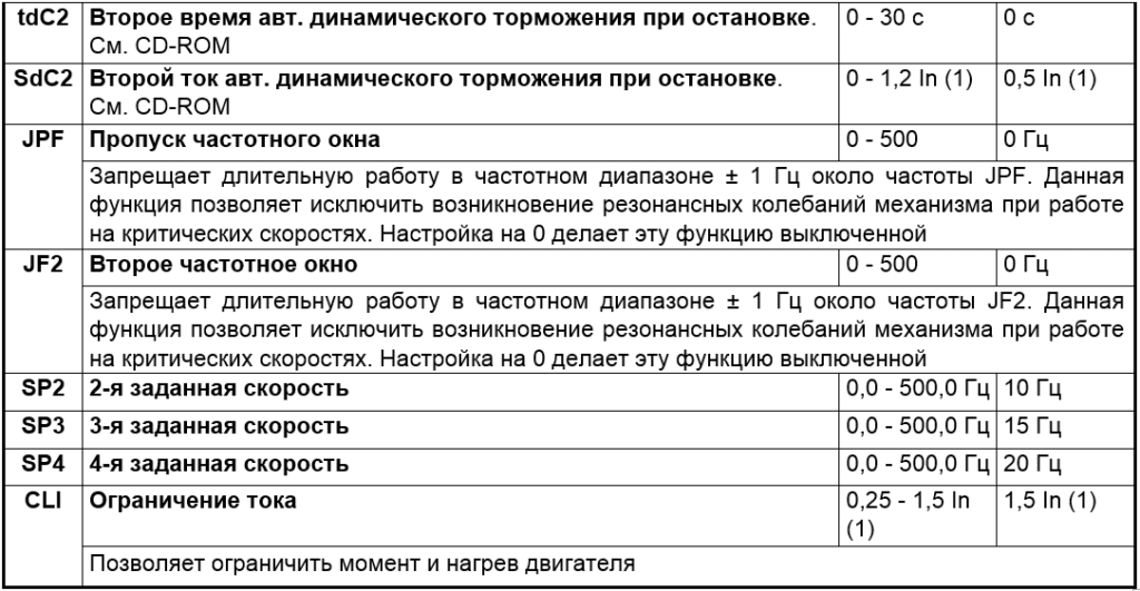



 так что одним драйвером дело не обойдётся.