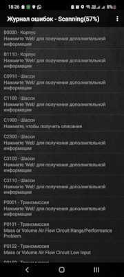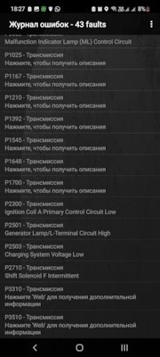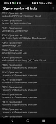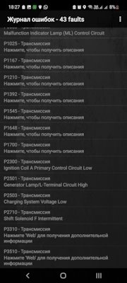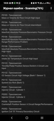
Всем привет, выручайте, у меня серые ошибки на черном фоне, и много их что это ?

Попробуй сбросить их …Они почти все повторяющиеся масса шасси.

Сбросил через обд китайский, они опять вылезли

Condor488
Попробуй сбросить их …Они почти все повторяющиеся масса шасси.
Машина работает исправна, чеков нет, Torque видит 42 ошибки на этом фоне, другие проги не видят не одной ошибки, испробовал 4 проги, на диогностике сказали нет ошибок,

Значит забей .У меня торкуе про- сбросишь и после пока новые не появятся все чисто .Случаем не с диска торкуе брал?


ну не знаю как помочь.Попробуй очистить лог в настройках


Condor488
Попробуй сбросить их …Они почти все повторяющиеся масса шасси.

Condor488
Попробуй сбросить их …Они почти все повторяющиеся масса шасси.

Condor488
Попробуй сбросить их …Они почти все повторяющиеся масса шасси.

верно.
красные отображаются в виде чека на приборной панели. зеленые (для меня желтые) могут пропадать через некоторое время, в том случае если ошибка не регистрируется какое то количество циклов(запуска двигателя или полного прогрева двигателя и т. п.)

Чуть яснее стало !)))С праздником!

Красные ошибки-Текущие, на данный момент имеющиеся .А вот зеленые -возникающие нерегулярно висящие ошибки.

Я хоть буду тоже знать 

Но есть и третий вид ошибок-ЧЁРНЫЕ?Что за зверь ?

А вот с черными я ещё не сталкивался О_о

сам офигел РО132 на сером фоне.
Привет всем. Многим пользователям приложения просто необходима инструкция Torque Pro на русском, но как таковой её не существует. Приходится довольствоваться найденными статьями тех, кто уже пользовался набрав небольшой опыт.
В этом материале я также попытаюсь поделиться своим опытом использования программы Torque для устройств на Андроид, так как имею автомобиль и не раз проводил его диагностику.
Для тех, кто впервые столкнулся с этим приложением поясню. Эта программа работает на всех устройствах оснащенных операционной системой Андроид помогая считывать параметры бортового компьютера автомобиля в паре с устройством типа Smart Scan Tool Pro, Elm327 и других. Используя эти две штучки можно самостоятельно провести диагностику автомобиля, при необходимости сбросить ошибку.
Содержание
- Сканер Scan Tool Pro
- Подключение Scan Tool Pro и Torque Pro
- Настройка профиля
- Настройка приложения Torque Pro
- Приборная панель
- Проверка на ошибки
- Обзор на карте
- Результаты испытаний
- Графики
Сканер Scan Tool Pro
Прежде чем приступить к разбору приложения Torque Pro хотелось бы немного зацепить само устройство Smart Scan Tool, так как их появилось в последнее время много и по цене имеют приличный разбег. Названия у них могут быть разные, но принцип работы один.
Не стремитесь покупать дешевые китайские адаптеры, которые предлагает Алиэкспресс. Огромная вероятность того, что оно не будет работать вообще. Берите, там, где есть гарантия и продавец несет ответственность за свой товар.
Оригинальное устройство Scan Tool Pro или Smart Scan Tool Pro должно иметь микроконтроллер от канадских производителей, то что продают в России и странах СНГ это преимущественно Китай. Отлично работает Корейская сборка (ссылки на них в тексте). Основная масса устройств имеет более дешевый вариант микроконтроллера и различные прошивки, соответственно их стоимость низкая. Но я не хочу сказать, что они не будут работать. Они работают и довольно неплохо. Вам лишь остается подобрать то устройство, которое будет работать на вашем автомобиле, а может и не будет.
Есть информация, что считывание данных с компьютера автомобиля зависит от прошивки. И это действительно так. Приведу пример.
Моему автомобилю Шевроле Авео отлично подошло устройство с версией прошивки 2.1, но не захотело работать на автомобилях ВАЗ и Нисанн (на других моделях не пробовал).
Устройство с прошивкой 1.5 – 1.6 способно охватывать практически все модели автомобилей. Оригинальная прошивка, как утверждают производители, работает на любом автомобиле. В отличии от оригинала часть функций на “поддельных” устройствах утрачено, это не критично.
Стоимость устройства в первую очередь зависит от производителя и комплектации. Половина стоимости комплекта может тянуть поставляемый с устройством софт. Покупая комплект Smart Scan Tool Pro, мы тем самым обезопасим себя в плане синхронизации адаптера с устройством вывода данных, уж точно между собой они будут работать, как говорится “фирма гарантирует”.
Диагностика на компьютере с использованием программы Scan Master
Подключение Scan Tool pro и Torque Pro
Для того чтобы приложение Torque Pro начало сбор данных необходимо:
1. Найти разъем диагностики автомобиля, подключить сканер. Обычно он находится под панелью приборов или под рулевым колесом. На некоторых моделях он выведен на центр панели, между водителем и пассажиром. После подключения на адаптере должен загореться светодиод.
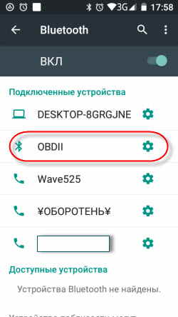
2. Следующий этап, это подключение адаптера с телефоном. В этом шаге нужно включить Blutooth, активировать поиск. Как только, произойдет синхронизация в настройках смартфона появиться новое устройство OBDII.
Для старых прошивок 1.5 – 1.6, возможно, потребуется ввести пароль “0000”, “1234” или “6789”. В моем случае пароль не потребовался.
В дальнейшем эту процедуру проделывать не придется, после запуска приложения Torque, включится Blutooth и произойдет синхронизация устройств.
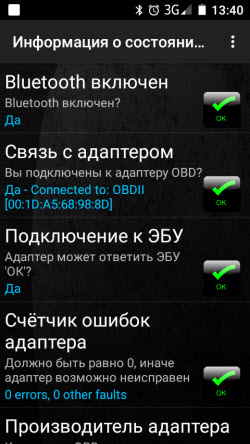
3. Повернув ключ зажигания (без запуска двигателя), переходите во вкладку на главной панели “Состояние адаптера”. Если все сделали правильно, то должны стоять четыре зеленых галочки.
- Blutooth включен (на обоих устройствах)
- связь с адаптером (устройства синхронизированы)
- подключение к ЭБУ (соединение с компьютером)
- счетчик ошибок
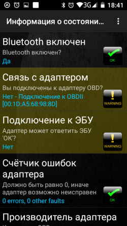
Но бывает и по-другому, когда одна из галочек не проставляется, чаще всего бывает отсутствие подключения к ЭБУ. Об этом говорилось выше, прошивка не видит компьютер.
Настройка профиля
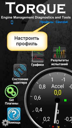
Первым делом нужно настроить “Профиль”. Перейти для заполнения, редактирования профиля можно в верхнем правом углу экрана, тапнув на надпись.
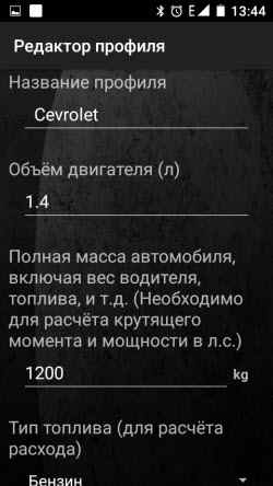
Здесь необходимо заполнить некоторые параметры:
-
- Название профиля (любое)
- объем двигателя (реальный)
- полную массу автомобиля (по паспорту)
- тип топлива
- объем топливного бака
- уровень топлива
- максимальное значение тахометра
- можно еще и стоимость топлива
Последний пункт “Коррекция экономичности” выставляется в процессе диагностики. Все эти данные будут учитываться приложением для некоторых подсчетов.
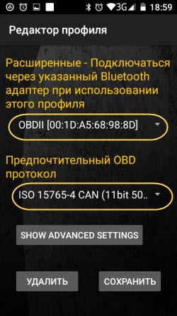
В конце имеется кнопка “SHOW ADVANCED SETTINGS” – расширенные настройки.
Здесь рекомендуется установить следующие значения.
- Подключаться через указанный Blutooth (выбрать из списка)
- предпочтительный протокол OBD (выбрать из списка)
Кнопкой “Сохранить” завершите настройку профиля.
Приложение для проверки штрафов ГИБДД
Видеорегистратор из смартфона на Андроид
Навигатор на смартфоне
Настройка приложения Torque Pro
Теперь переходим к настройкам приложения. В левом углу экрана имеется шестерня, тап по ней откроет “Меню”, где и перейдем к настройкам. Здесь рассмотрим только необходимые пункты настроек.
Основные настройки
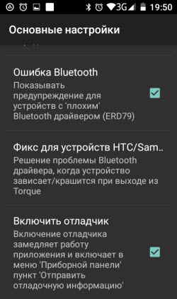
Здесь нужно отметить галочками только четыре пункта:
- Показать панель уведомлений
- автоповорот
- ошибка Blutooth
- включить отладчик
Темы
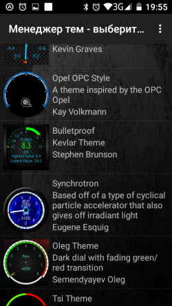
Эту настройку оставляю на ваше усмотрение. Она отвечает за оформление панели приборов, фонового изображения.
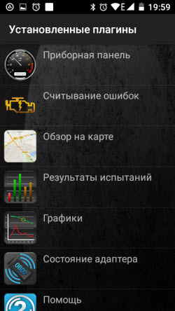
Плагины
Приложение работает за счет установленных плагинов список которых можно пополнить нажав соответствующую ссылку с названием в самом низу.
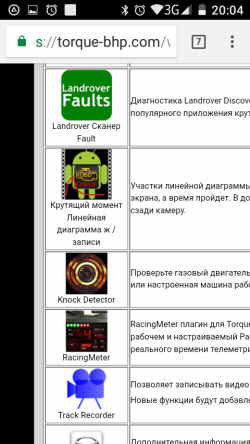
Произойдет переход на страницу с дополнительными плагинами. На мой взгляд, они могут подойти только продвинутому и фанатеющему от диагностики пользователю.
Основного пакета вполне хватит для получения детальной информации. Эти же и другие плагины можно скачать в Плэй Маркет.
Единицы измерения
Здесь нельзя навязывать свою позицию. У каждого свои единицы измерения. Думаю, вы сделаете правильный выбор. Мой выбор пал:
- градусы
- килограммы
- psi
- ньютонометры
Настройки адаптера OBD
В этом пункте отметьте только первые три настройки
- авто Вкл/Выкл Blutooth (при запуске программы произойдет автоматическое включение Blutooth и выключение после закрытия программы.
- если ВТ был выключен ( как бы дублирует предыдущую)
- быстрое подключение (здесь понятно без комментариев)
Запись и выгрузка журналов
Эту настройку можно проигнорировать, а можно и покопаться в ней, если вы планируете собирать данные считанные с датчиков. Возможно ведение журнала кому-то пригодится.
Панель приборов
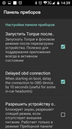
В этом разделе я ничего не отмечал, но если держать программу в активном состоянии, поставьте первые две галочки. Рекомендовано для Андроид устройств.
- Запустить Torque после перезагрузки
- Delayed obd connection
Речь/Предупреждения
В свою очередь, интересная настройка. Предупреждение голосом о некоторых важных моментах в работе двигателя (если эти функции поддерживаются компьютером).
- низкая температура
- уровень топлива
- достижение двигателем рабочей температуры
Здесь также на усмотрение пользователя.
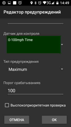
Управление предупреждениями
Этот пункт является дополнением предыдущего и осуществляет вывод на панель настроенные предупреждения
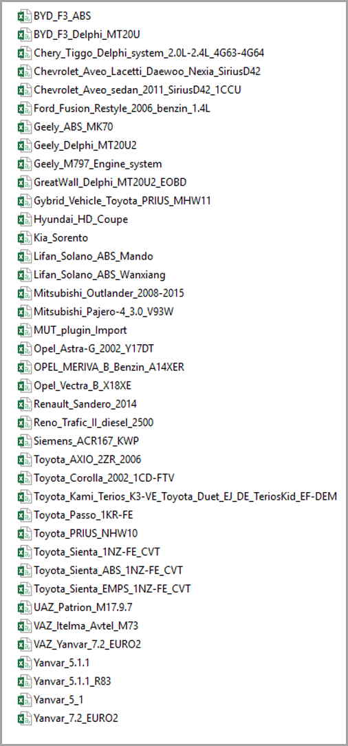
Пиды (PID) для Torque Pro
Важный момент. Для каждого автомобиля имеется файл с набором дополнительных датчиков. В программе по умолчанию находится всего несколько моделей. Вам нужно найти и загрузить файл под ваш автомобиль.
Ссылки где поискать даю:
Torque Pro руссифицированный для Андроид на Google Play Тут на 4PDA —Тут (халява)
PIDы (файлы) – Здесь
Смотрите, есть ли нужный вам PID в списке и забирайте одним файлом.
Забрать
Установка файла
-
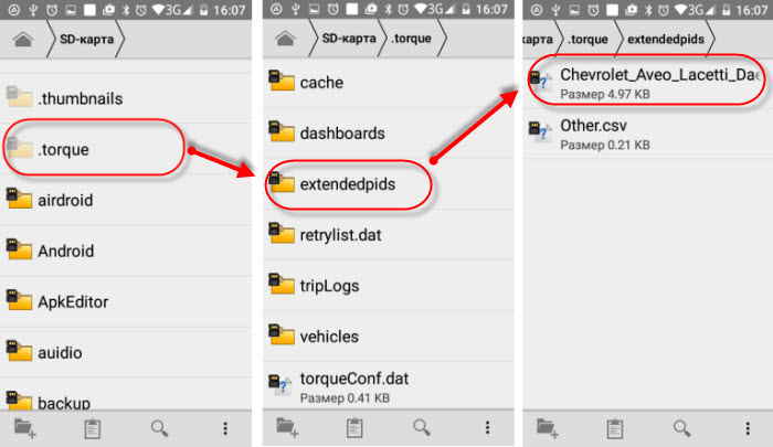
- Находите файл программы “torque”.
- Далее, нужно найти скрытый файл “extendedpids”. В диспетчере файлов включите функцию “Показать скрытые файлы”.
- Закидываете файл “csv” в эту папку.
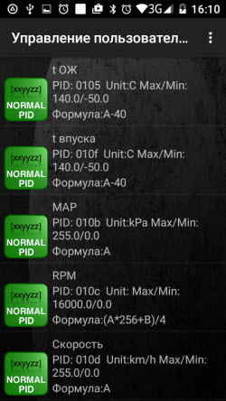
- В управлении доп. датчиками жмете “Добавить набор”
- В открывшемся окне увидите загруженный вами файл и выбираете.
Все готово. Произошла загрузка дополнительных PID датчиков в приложение.
На этом этапе с настройками можно закончить. Оставшиеся не важны и поэтому не будем тратить на них время.
Приборная панель
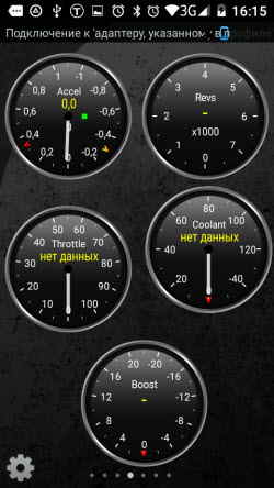
Теперь остается настроить панель и вывести на неё необходимые датчики. По умолчанию в программе уже выставлено несколько приборов учета, но можно добавить те, которые вы считаете нужными.
С главной страницы приложения переходите в “Приборная панель”. Жмете на пустой экран и ждете появления оповещения “Настройка элемента” и далее “Добавить прибор”.
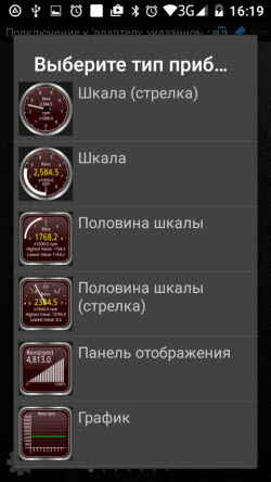
Следующим шагом выбираете наиболее симпатичную вам шкалу и тапните на неё.
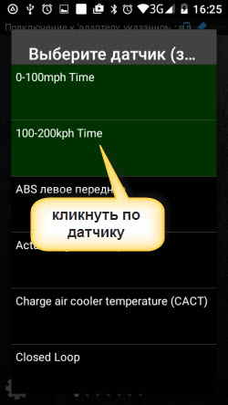
Теперь нужно выбрать интересующий вас датчик. Выбирать нужно только зеленые датчики, остальные показаний не дадут. В зависимости от автомобиля количество активных датчиков разное.
Список большой, есть где покопаться.
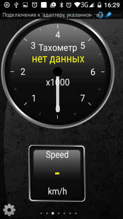
Каждый выведенный элемент на приборную панель можно настраивать (нажать и подождать):
- изменить размер
- сбросить данные
- переместить
- сделать плавающим
- удалить
На этом подготовку приложения к работе заканчиваем. Запускаете двигатель и наслаждайтесь полученными результатами.
Остались не охвачены несколько функций приложения и вкратце мы их рассмотрим.
Проверка на ошибки
Для проверки наличия ошибок переходите с главной в “Считывание ошибок”, запускаете поиск. Через некоторое время приложение покажет результат.
Как сбросить ошибку смотрите в видео. Главное помните, сбросив ошибку и не устранив неисправность она появиться вновь. Появление ошибки это сигнал к действию.
Но бывает и наоборот, неисправность устранена а ошибка не сбрасывается. Вот тут поможет Elm327 и Torque Pro.
Обзор на карте
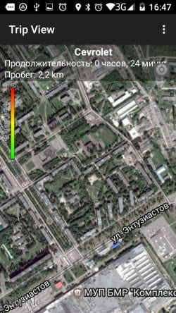
После запуска приложения будет запрос на включение GPS. Активировав его, программа будет записывать все ваши поездки и показывать их на карте. В последствии вы можете поделиться ими, просмотреть и удалить.
Результаты испытаний
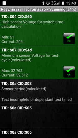
Вот здесь, каюсь, я толком ничего не понял. Понятно только то, что отмеченные зеленым цветом датчики это значит нормально.
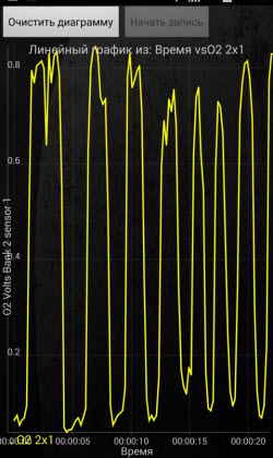
Графики
Обычно цифровая информация лучше воспринимается при помощи графиков. Такая возможность предоставлена этим плагином.
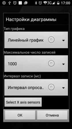
Для начала необходимо настроить график выбрав:
- вид
- число записей
- интервал опроса
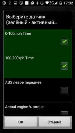
Кнопкой “Selekt X axis sensors” добавить нужные датчики и сохранить.
Вот такая получилась инструкция torque pro на русском языке. Я старался дать информацию по максимуму. Если возникнут трудности или что-то непонятно, пишите в комментариях. Будем смотреть и разбираться.
-
Check Engine error code 140: Engine Torque -Bank Comparison.
Update: 4/15/2021, 7:34PM. This problem identified and FIXED !! Please scroll to end, will update.
old post:
My mechanic is getting this error code 140: Engine Torque -bank comparison. Does anyone know what this means ? This is a new error that is coming up now after he went through replacement of intake manifold gasket, valve cover gasket, and the rear main crankshaft seals.Last edited by sshivaram; 04-15-2021 at 07:35 PM.
-
I think throttles need to be synchronized
-
Did he resync the throttle bodies?
drive car till the engine has reached operating tempfind a relatively flat stretch of road.
stop car, put in 1st gear,
briskly accelerate till the rpm goes past 5000 rpm
now coast to a Complete Stop by using the brakes, foot off the gas
count till 5…briskly accelerate till the rpm goes past 5000 rpm
now coast to a Complete Stop by using the brakes, foot off the gas
count till 5 …briskly accelerate till the rpm goes past 5000 rpm
now coast to a Complete Stop by using the brakes, foot off the gas
(yep, da’s doing it 3 times)after the third time coming to a complete stop, put car in park and let the engine idle for at least 5 minutes, don’t take shortcuts here.
Shogun tricks and tips for the E32 series are HERE!
-
Its a 1995, with 100K miles now. He did the TB sync procedure. The car idles very rough now, and works perfectly at high RPMs(highway speeds). It passed the emission at high RPMs and failed the emissions for idle RPM(HC was 580, allowed is 220). So, its throwing lot of unburnt fuel into the exhaust pipes. While changing the intake manifold gasket and valve cover gaskets, it appears like something was not done correctly. What could be wrong here ? Thanks for the replies !
-
it appears like something was not done correctly
Can be many things, check for example on my website the write up with many pics http://twrite.org/shogunnew/topmenu.html click on left fixes>>go to engine general>>>Top end overhaul, 68 pages
For example the vacuum hoses on the fuel pressure regulators can be mixed up, or the connectors of the sensors.
Shogun tricks and tips for the E32 series are HERE!
-
Ok, This is where we are now. The high HC at idle rpm indicates «misfire» per another thread i read(and I can’t find it now). The engine shakes a lot, rattles the exhaust and its idle is at around 750rpm, while it should be less than or equal to the 500 mark line there. At higher rpm (1500+), works like a charm and passes emission. The mechanic has thrown in the towel and can’t figure out.
Work done on it: Changed spark plugs, ignition wires, intake manifold gasket, valve gasket, rear main seal that was leaking.
The car has awesome power now with no leaks (Smoke test), but this idle RPM Check engine light with error 140 (Engine Torque -Bank Comparison.) still comes up at idle RPM. It won’t come at high speeds, and at idle smells of gas.
-
I wanted to rake this up. Problem (rough idle, vibrations, smells of gas in the Driver Side exhaust) is still present. This is where we are:
I took the MAF sensor readings on Left (Passenger side) and Right (Driver Side) bank.The Left is always about 0.2 volts less than Right side.
I swapped the MAF sensors, and swapped the Throttle Bodies, with no change in the readings.Here are the readings at different intervals:
Power On: Left 0.12 Volts Right 0.12 Volts
Start engine 1.07 volts 1.28 volts
(~ 1000 rpm)Shift to Drive 0.79 volts 1.01 volts
(~600 rpm)In Neutral 1.26 volts 1.45 volts
(rev to 1500 rpm)What is causing this ? Mechanic needs help !!
-
What were the spark plugs he fitted?
-
To Summarize: He changed spark plugs, wires, distributor, intake manifold gasket, valve cover. Spent a lot of time on it.
He had installed the NGK Spark plugs (its recommended on the computer) , and I took them out and replaced with Bosch F8LCR. Still no change in the rough idle and burning gas in emissions.
-
When you removed the plugs — were some wet with petrol? Any black and sooty ones?
-
No, they were clean.
At idle RPM 550, what should be the typical voltage readings on the MAF sensor (air flow ?). The Left is 0.79 and right is 1.01 volts. So, less air is going into the Left sensor and into the Right cylinder banks (intake manifold crosses over right). This causes it to burn up fuel and I smell gas in the right side (driver side) tail pipe. The Left and Right cylinder banks are producing unequal power, causing the roughness and vibrations. At higher RPM, the voltage difference still sticks at 0.2 volts, and the vibrations is not noticeable. If the Check Engine light is cleared (Toque imbalance), we can drive car all day long without issues and passes emission also. However, when we keep it at idle, after few mins, the check engine light is triggered with the Torque imbalance code.— — — Updated — — —Thanks for taking the time !!
-
Originally Posted by sshivaram
To Summarize: He changed spark plugs, wires, distributor, intake manifold gasket, valve cover. Spent a lot of time on it. He had installed the NGK Spark plugs (its recommended on the computer) , and I took them out and replaced with Bosch F8LCR. Still no change in the rough idle and burning gas in emissions.
I also had a rough idle problem and failed emissions with high HC (254 vs 60 allowed) and the exhaust smelled a bit. I changed my PCVs (VCV actually) and associated hoses and it seemed to run a little better. But what really seemed to help was new plugs. I put in the Bosch F8LCRs last year, but apparently they changed the plug and resistance is now too high (6k vs 1k). So I changed them out to the NKG BKR6EK and now it seems to run much better. I can’t tell if it cured my emissions problem (the car turned 25 four days before I brought it back in so I am now exempt [I know, said it a million times]), but it definitely runs much nicer.
As an FYI, I order them from SixtyAuto which seemed to have the cheapest price. 6 for $24.16 with free shipping. Plus I ordered them on a Friday afternoon and got them Monday (CA to CT). Here’s a link;
http://www.sixityauto.com/6-pc-6-x-n…p-kit-set.htmlMy Cars — 1991 BMW 850i — mine for fun, 1993 Saab 900c — mine for fun, 2008 Lexus is250 — my daily driver, 2003 Dodge Durango — my wife’s, 1994 Acura Legend — gave it to kid
-
Just spent 2 hours with the mechanic.
We plugged in the vacuum gauge and the Left Throttle shows 16psi, and Right shows 13psi.
We swapped the throttle bodies and the Left still shows 16psi, with right showing 13psi, while running the engine at 1000 rpm after start up in Parking.
So, the Left intake manifold (sending air to Right cylinders) has more vacuum than right side.
The mechanic knows everything, he just wants to be convinced he has to spend 8-10 hours of his time taking the intake manifold off and getting back into it again. There is a valve inside each side that controls the vacuum he says, and its possible its sticking or operating incorrectly.
The Left and Right air-flow through MAF sensor *always* show the 0.2 volt difference (Right sensor is higher always).
-
Sounds like you oxygen sensors are plugged into the wrong connectors, swap them over and see how it drives .
-
That is an interesting lead to explore. He had gone pretty deep into the engine — changed intake manifold gasket and valve covers, and its possible this may be the case. Will have this checked out asap ! Thank you.
-
Found another thread here, where Left bank had 18psi and right bank had 13psi in a 750iL. It was because of intake manifold gaskets. In my case, they were replaced, and there is a good chance something wasn’t aligned or torqued correctly. Re-doing the intake manifold.
-
You really want to ignore what the spark plug manufacturers recommend, as they all have 5k ohm or more resistors. BMW spec ‘d. The system to work with 1000 ohm plugs. I use NGK BKR6EK dual ground electrode plugs which are 1000 ohm resistor plugs. They are one heat range colder than specification, but work very well. If you use a higher resistance plug, it chokes down the electrical pulse measured by the can sensor doughnuts on cylinders 6 & 12, and the car will throw codes, go into limp home mode, Trans program failure on the display for automatic cars, lots of fun. Sticky Bosch DK’s can also cause these problems, or if they have worn sensor tracks on their variable resistor plates, or if the wiper arms are out of synch, throttle shaft bore leakage? I would also check for vacuum leakage on the hoses to the charcoal canister, or a hole in the canister itself, as they get corroded from leakage from the windshield washer fluid reservoir. In the end, you may be right about the intake gaskets. Did you replace injector o rings?
-
Originally Posted by Mikekugel
You really want to ignore what the spark plug manufacturers recommend, as they all have 5k ohm or more resistors. BMW spec ‘d. The system to work with 1000 ohm plugs. I use NGK BKR6EK dual ground electrode plugs which are 1000 ohm resistor plugs. They are one heat range colder than specification, but work very well. If you use a higher resistance plug, it chokes down the electrical pulse measured by the can sensor doughnuts on cylinders 6 & 12, and the car will throw codes, go into limp home mode, Trans program failure on the display for automatic cars, lots of fun. Sticky Bosch DK’s can also cause these problems, or if they have worn sensor tracks on their variable resistor plates, or if the wiper arms are out of synch, throttle shaft bore leakage? I would also check for vacuum leakage on the hoses to the charcoal canister, or a hole in the canister itself, as they get corroded from leakage from the windshield washer fluid reservoir. In the end, you may be right about the intake gaskets. Did you replace injector o rings?
Could not have said it better myself!
-
One more thing comes to mind. Did your mechanic check the Cam timing when he had the valve covers off?
-
I don’t know if he checked the Cam timing. He went in to replace intake manifold gaskets, and we have around 16psi on Left bank and 13psi on right. So, he will re-do the intake manifold now. It has new gaskets. Hopefully, align them and try to toque it down again, and no need to get new gaskets. He should cover it !!
On the spark plugs, I have put in Bosch F8LCR. Its definitely not the MAS sensors or Throttles since I swapped them and the readings are always higher on the Left bank. I also changed throttles from a used one I bought on ebay for $35 which works perfectly and gives the same readings (New retail is around $1500-$2200)
-
Update:
Indy took the whole intake manifold and valve cover off, everything. Put it back. Same problem !
He claims I need 2 new «identical» throttle bodies, about $3000 in parts.
I think he is off !
Just realized something: The car has no power. Takes about 13 seconds to hit 0-60mph (Spec is about 5.4 seconds). It reaches full redline and has lost the power. Are we possibly looking at pinched fuel lines, wouldn’t loss of fuel lead to loss of power with everything else working correctly, and cause an imbalance in the bank that is not having enough fuel injected. The engine shakes a lot at idle RPM.
-
Originally Posted by sshivaram
Update:
Indy took the whole intake manifold and valve cover off, everything. Put it back. Same problem !
He claims I need 2 new «identical» throttle bodies, about $3000 in parts.
I think he is off !
Just realized something: The car has no power. Takes about 13 seconds to hit 0-60mph (Spec is about 5.4 seconds). It reaches full redline and has lost the power. Are we possibly looking at pinched fuel lines, wouldn’t loss of fuel lead to loss of power with everything else working correctly, and cause an imbalance in the bank that is not having enough fuel injected. The engine shakes a lot at idle RPM.OK, if you need throttles I can provide rebuilt units for much less, but before we go there wanna make sure we are talking about the right car, you mentioned 1995? is this still M70 engine or a M73 with Siemens throttles??— — — Updated — — —
Are you guys sure car is running on all 12?? Sounds like a dead bank to me.
— — — Updated — — —
Grab one side of the exhaust and see if it is cooler than the other side, you fuel pump may have been failing and now failed.
Did you swap coils side to side?— — — Updated — — —
Measure fuel flow on both pumps at the back of the engine by disconnecting fuel hoses and inserting them into 2 coke cans, then manually apply voltage to fuel pumps under the pass rear seat(upper pin is ground) time each pump, look at the flow and compare.
BTW your used ebay throttle does not work «perfectly» no offense.
-
Its a 1995. It has the Siemens throttle bodies — can’t be rebuilt. They are epoxy sealed. There is nothing wrong with the throttle bodies. When i swap them, the left bank and right banks still have the same readings. I got a used one from ebay for $35 free shipping and there is absolutely no change in the readings on the left and right bank. Its not the throttle bodies. I will ask him to check the fuel pressure.— — — Updated — — —
>> BTW your used ebay throttle does not work «perfectly» no offense.
What makes you say that. I am the one changing them and checking their readings. At most throttle positions, I got the same air flow readings off of a multimeter using 4 different throttle bodies — 2 are original, and 2 are from ebay for $35 and $75.
before-after.JPG
-
Yes you are right on Siemens throttles, can’t be rebuilt. The throttles themselves are probably fine.
Alot of the comments above were geared towards the M70 engine, the synchronization procedure is very different on M73:
Turn the ignition on but don’t start the engine.
Leave the key on for 30 sec.
Turn the key off then start the engine.
Done.BTW DON’T EVEN THINK RESETTING ADAPTATION IN INPA OR DIS! LONG STORY LOL
Last edited by dragon850; 06-22-2016 at 12:27 AM.
-
Привет всем. Многим пользователям приложения просто необходима инструкция Torque Pro на русском, но как таковой её не существует. Приходится довольствоваться найденными статьями тех, кто уже пользовался набрав небольшой опыт.
В этом материале я также попытаюсь поделиться своим опытом использования программы Torque для устройств на Андроид, так как имею автомобиль и не раз проводил его диагностику.
Для тех, кто впервые столкнулся с этим приложением поясню. Эта программа работает на всех устройствах оснащенных операционной системой Андроид помогая считывать параметры бортового компьютера автомобиля в паре с устройством типа Smart Scan Tool Pro, Elm327 и других. Используя эти две штучки можно самостоятельно провести диагностику автомобиля, при необходимости сбросить ошибку.
Содержание
- Сканер Scan Tool Pro
- Подключение Scan Tool Pro и Torque Pro
- Настройка профиля
- Настройка приложения Torque Pro
- Приборная панель
- Проверка на ошибки
- Обзор на карте
- Результаты испытаний
- Графики
Сканер Scan Tool Pro
Прежде чем приступить к разбору приложения Torque Pro хотелось бы немного зацепить само устройство Smart Scan Tool, так как их появилось в последнее время много и по цене имеют приличный разбег. Названия у них могут быть разные, но принцип работы один.
Не стремитесь покупать дешевые китайские адаптеры, которые предлагает Алиэкспресс. Огромная вероятность того, что оно не будет работать вообще. Берите, там, где есть гарантия и продавец несет ответственность за свой товар.
Оригинальное устройство Scan Tool Pro или Smart Scan Tool Pro должно иметь микроконтроллер от канадских производителей, то что продают в России и странах СНГ это преимущественно Китай. Отлично работает Корейская сборка (ссылки на них в тексте). Основная масса устройств имеет более дешевый вариант микроконтроллера и различные прошивки, соответственно их стоимость низкая. Но я не хочу сказать, что они не будут работать. Они работают и довольно неплохо. Вам лишь остается подобрать то устройство, которое будет работать на вашем автомобиле, а может и не будет.
Есть информация, что считывание данных с компьютера автомобиля зависит от прошивки. И это действительно так. Приведу пример.
Моему автомобилю Шевроле Авео отлично подошло устройство с версией прошивки 2.1, но не захотело работать на автомобилях ВАЗ и Нисанн (на других моделях не пробовал).
Устройство с прошивкой 1.5 – 1.6 способно охватывать практически все модели автомобилей. Оригинальная прошивка, как утверждают производители, работает на любом автомобиле. В отличии от оригинала часть функций на “поддельных” устройствах утрачено, это не критично.
Стоимость устройства в первую очередь зависит от производителя и комплектации. Половина стоимости комплекта может тянуть поставляемый с устройством софт. Покупая комплект Smart Scan Tool Pro, мы тем самым обезопасим себя в плане синхронизации адаптера с устройством вывода данных, уж точно между собой они будут работать, как говорится “фирма гарантирует”.
Диагностика на компьютере с использованием программы Scan Master
Подключение Scan Tool pro и Torque Pro
Для того чтобы приложение Torque Pro начало сбор данных необходимо:
1. Найти разъем диагностики автомобиля, подключить сканер. Обычно он находится под панелью приборов или под рулевым колесом. На некоторых моделях он выведен на центр панели, между водителем и пассажиром. После подключения на адаптере должен загореться светодиод.
2. Следующий этап, это подключение адаптера с телефоном. В этом шаге нужно включить Blutooth, активировать поиск. Как только, произойдет синхронизация в настройках смартфона появиться новое устройство OBDII.
Для старых прошивок 1.5 – 1.6, возможно, потребуется ввести пароль “0000”, “1234” или “6789”. В моем случае пароль не потребовался.
В дальнейшем эту процедуру проделывать не придется, после запуска приложения Torque, включится Blutooth и произойдет синхронизация устройств.
3. Повернув ключ зажигания (без запуска двигателя), переходите во вкладку на главной панели “Состояние адаптера”. Если все сделали правильно, то должны стоять четыре зеленых галочки.
- Blutooth включен (на обоих устройствах)
- связь с адаптером (устройства синхронизированы)
- подключение к ЭБУ (соединение с компьютером)
- счетчик ошибок
Но бывает и по-другому, когда одна из галочек не проставляется, чаще всего бывает отсутствие подключения к ЭБУ. Об этом говорилось выше, прошивка не видит компьютер.
Настройка профиля
Первым делом нужно настроить “Профиль”. Перейти для заполнения, редактирования профиля можно в верхнем правом углу экрана, тапнув на надпись.
Здесь необходимо заполнить некоторые параметры:
-
- Название профиля (любое)
- объем двигателя (реальный)
- полную массу автомобиля (по паспорту)
- тип топлива
- объем топливного бака
- уровень топлива
- максимальное значение тахометра
- можно еще и стоимость топлива
Последний пункт “Коррекция экономичности” выставляется в процессе диагностики. Все эти данные будут учитываться приложением для некоторых подсчетов.
В конце имеется кнопка “SHOW ADVANCED SETTINGS” – расширенные настройки.
Здесь рекомендуется установить следующие значения.
- Подключаться через указанный Blutooth (выбрать из списка)
- предпочтительный протокол OBD (выбрать из списка)
Кнопкой “Сохранить” завершите настройку профиля.
Приложение для проверки штрафов ГИБДД
Видеорегистратор из смартфона на Андроид
Навигатор на смартфоне
Настройка приложения Torque Pro
Теперь переходим к настройкам приложения. В левом углу экрана имеется шестерня, тап по ней откроет “Меню”, где и перейдем к настройкам. Здесь рассмотрим только необходимые пункты настроек.
Основные настройки
Здесь нужно отметить галочками только четыре пункта:
- Показать панель уведомлений
- автоповорот
- ошибка Blutooth
- включить отладчик
Темы
Эту настройку оставляю на ваше усмотрение. Она отвечает за оформление панели приборов, фонового изображения.
Плагины
Приложение работает за счет установленных плагинов список которых можно пополнить нажав соответствующую ссылку с названием в самом низу.
Произойдет переход на страницу с дополнительными плагинами. На мой взгляд, они могут подойти только продвинутому и фанатеющему от диагностики пользователю.
Основного пакета вполне хватит для получения детальной информации. Эти же и другие плагины можно скачать в Плэй Маркет.
Единицы измерения
Здесь нельзя навязывать свою позицию. У каждого свои единицы измерения. Думаю, вы сделаете правильный выбор. Мой выбор пал:
- градусы
- килограммы
- psi
- ньютонометры
Настройки адаптера OBD
В этом пункте отметьте только первые три настройки
- авто Вкл/Выкл Blutooth (при запуске программы произойдет автоматическое включение Blutooth и выключение после закрытия программы.
- если ВТ был выключен ( как бы дублирует предыдущую)
- быстрое подключение (здесь понятно без комментариев)
Запись и выгрузка журналов
Эту настройку можно проигнорировать, а можно и покопаться в ней, если вы планируете собирать данные считанные с датчиков. Возможно ведение журнала кому-то пригодится.
Панель приборов
В этом разделе я ничего не отмечал, но если держать программу в активном состоянии, поставьте первые две галочки. Рекомендовано для Андроид устройств.
- Запустить Torque после перезагрузки
- Delayed obd connection
Речь/Предупреждения
В свою очередь, интересная настройка. Предупреждение голосом о некоторых важных моментах в работе двигателя (если эти функции поддерживаются компьютером).
- низкая температура
- уровень топлива
- достижение двигателем рабочей температуры
Здесь также на усмотрение пользователя.
Управление предупреждениями
Этот пункт является дополнением предыдущего и осуществляет вывод на панель настроенные предупреждения
Пиды (PID) для Torque Pro
Важный момент. Для каждого автомобиля имеется файл с набором дополнительных датчиков. В программе по умолчанию находится всего несколько моделей. Вам нужно найти и загрузить файл под ваш автомобиль.
Ссылки где поискать даю:
Torque Pro руссифицированный для Андроид на Google Play Тут на 4PDA —Тут (халява)
PIDы (файлы) – Здесь
Смотрите, есть ли нужный вам PID в списке и забирайте одним файлом.
Забрать
Установка файла
-
- Находите файл программы “torque”.
- Далее, нужно найти скрытый файл “extendedpids”. В диспетчере файлов включите функцию “Показать скрытые файлы”.
- Закидываете файл “csv” в эту папку.
- В управлении доп. датчиками жмете “Добавить набор”
- В открывшемся окне увидите загруженный вами файл и выбираете.
Все готово. Произошла загрузка дополнительных PID датчиков в приложение.
На этом этапе с настройками можно закончить. Оставшиеся не важны и поэтому не будем тратить на них время.
Приборная панель
Теперь остается настроить панель и вывести на неё необходимые датчики. По умолчанию в программе уже выставлено несколько приборов учета, но можно добавить те, которые вы считаете нужными.
С главной страницы приложения переходите в “Приборная панель”. Жмете на пустой экран и ждете появления оповещения “Настройка элемента” и далее “Добавить прибор”.
Следующим шагом выбираете наиболее симпатичную вам шкалу и тапните на неё.
Теперь нужно выбрать интересующий вас датчик. Выбирать нужно только зеленые датчики, остальные показаний не дадут. В зависимости от автомобиля количество активных датчиков разное.
Список большой, есть где покопаться.
Каждый выведенный элемент на приборную панель можно настраивать (нажать и подождать):
- изменить размер
- сбросить данные
- переместить
- сделать плавающим
- удалить
На этом подготовку приложения к работе заканчиваем. Запускаете двигатель и наслаждайтесь полученными результатами.
Остались не охвачены несколько функций приложения и вкратце мы их рассмотрим.
Проверка на ошибки
Для проверки наличия ошибок переходите с главной в “Считывание ошибок”, запускаете поиск. Через некоторое время приложение покажет результат.
Как сбросить ошибку смотрите в видео. Главное помните, сбросив ошибку и не устранив неисправность она появиться вновь. Появление ошибки это сигнал к действию.
Но бывает и наоборот, неисправность устранена а ошибка не сбрасывается. Вот тут поможет Elm327 и Torque Pro.
Обзор на карте
После запуска приложения будет запрос на включение GPS. Активировав его, программа будет записывать все ваши поездки и показывать их на карте. В последствии вы можете поделиться ими, просмотреть и удалить.
Результаты испытаний
Вот здесь, каюсь, я толком ничего не понял. Понятно только то, что отмеченные зеленым цветом датчики это значит нормально.
Графики
Обычно цифровая информация лучше воспринимается при помощи графиков. Такая возможность предоставлена этим плагином.
Для начала необходимо настроить график выбрав:
- вид
- число записей
- интервал опроса
Кнопкой “Selekt X axis sensors” добавить нужные датчики и сохранить.
Вот такая получилась инструкция torque pro на русском языке. Я старался дать информацию по максимуму. Если возникнут трудности или что-то непонятно, пишите в комментариях. Будем смотреть и разбираться.
PMSM drives control and simulation using MATLAB
V. Indragandhi Associate Professor, … V. Subramaniyaswamy Professor, in Electric Motor Drives and their Applications with Simulation Practices, 2022
7.2.2 Direct torque control
Direct torque control (DTC) circuits are less complicated than FOC circuits since they do not require the usage of a PWM inverter, a speed sensor, or reference frame transformers. Because information regarding the exact position of the rotor is not necessary in such systems, all computations are performed in the stator reference frame (except the start-up case of the synchronous motor). However, their steady-state functioning, especially at low speeds, is characterized by high stator current, flux linkage, and torque ripples, which severely limits their usage for high-precision drives. DTC with space vector modulation (SVM) is designed to solve the drawbacks of DTC. The pulse width modulation technique is used by DTC with SVM to generate the voltage. When compared to DTC, there are various circuit changes that considerably improve the control system’s efficiency.
Read full chapter
URL:
https://www.sciencedirect.com/science/article/pii/B9780323911627000072
Fault diagnosis and failure prognosis of electrical drives
Elias G. Strangas, in Fault Diagnosis and Prognosis Techniques for Complex Engineering Systems, 2021
4.1.2 Operation under Direct Torque Control
Direct torque control (DTC) replaces the decoupling in field-oriented control with bang-bang control, which naturally fits the inherently discrete nature of switch-mode power inverters. DTC does not involve space vector modulation but utilizes a switching table that consists of different voltage vectors. In addition, the rotor position sensing that is essential for FOC is not necessary for DTC to operate properly even if a speed control loop is included in the DTC scheme. Instead, the desired stator flux λ′ and torque T are established through comparators and voltage commands. Fig. 4.3 show a typical controller for direct torque control.
Almost all diagnosis and prognosis is based on the collection of operating data, and the design of a model—deterministic, stochastic, or entirely analytical. We should differentiate between data required to create a data-based model of the drive components and the data used to arrive at a decision for one device. The preceding is directly related to the time available to decide appropriate action and the accuracy of the decision.
Read full chapter
URL:
https://www.sciencedirect.com/science/article/pii/B9780128224731000082
Electrical Engineering Technologies Mathematics for Electrical Engineering
Angel Gonzalez-Prieto, … Mario J. Duran, in Encyclopedia of Electrical and Electronic Power Engineering, 2023
Direct torque control
Direct torque control schemes directly regulate the flux/torque production without a direct control of the stator currents. This regulation technique offers a simple control structure based on the use of two hysteresis controllers and predefined look-up tables (see Fig. 8) (Wu and Narimani, 2017). In contrast to FOC strategies, the synchronous reference frame rotation is not implemented in the case of DTC strategies to satisfy the speed regulation. Nevertheless, DTC schemes need to employ flux/torque observers to provide a suitable tracking of the reference speed (Wu and Narimani, 2017). As previously exposed, the main advantage of DTC over FOC appears in the field-weakening region. In high-speed operation, the magnetic flux can be directly estimated using a voltage model, where the amplitude of the flux reference is dependent on the stator resistance (Sun et al., 2020). Therefore, the flux estimation in DTC is not related to non-linear parameters, thus providing a simple and suitable performance in the field-weakening region of IMPSMs.
Fig. 8. Standard DTC scheme applied to a three-phase PMSM.
Read full chapter
URL:
https://www.sciencedirect.com/science/article/pii/B9780128212042000210
Basic Control Principles in Power Electronics
Ricardo P. Aguilera, … Jose I. Leon, in Control of Power Electronic Converters and Systems, 2018
2.4.2.2 Direct Torque Control/Direct Power Control
Direct torque control (DTC) for motor drive applications has been well established in both academia and industry. It offers a simple control structure, fast response, and robust operation [35]. The torque and flux references are tracked using hysteresis controllers and a switching table implemented with LUT is used for selecting the optimum converter’s output. Similarly, direct power control (DPC) for grid-connected applications was developed afterward to control the instantaneous active and reactive power directly by selecting the optimum switching state of the converter [36]. Fig. 2.21A illustrates the operation principle of DTC, and Fig. 2.21B its block diagram. Basically, DPC is the analog of DTC considering the instantaneous errors of active and reactive power instead instantaneous errors of torque and flux for reading the LUT.
Fig. 2.21. A DTC for a three-phase two-level power converter: (A) operation principle and (B) block diagram.
Read full chapter
URL:
https://www.sciencedirect.com/science/article/pii/B9780128052457000020
Electrical Machine Drives
W Drury BSC, PUD, CEng, FIEE, in Electrical Engineer’s Reference Book (Sixteenth Edition), 2003
19.4.2.5 Direct torque control
The drive control systems described so far all use space vector modulation to produce the inverter control signals. An alternative method of control that can be used when a motor is connected to the drive is direct torque control.
An example of a control system based on direct torque control is shown in Figure 19.37. The torque reference, Te*, and the flux magnitude reference, |φs|*, are derived in the same way as for a drive using a space vector modulator. The hysteresis comparators then produce the required change in flux and torque, and the switching table selects the required inverter state to give a voltage vector that will change the flux and torque as required. The angle of the stator flux, αφS, is used to determine which 60° sector the stator flux is in, as different areas of the switching table are used for different sectors.
Figure 19.37. Direct torque control system
The direct torque control system requires an estimate of the stator flux and the torque for the hysteresis comparators, and an estimate of rotor speed for the speed controller. These are derived from a model based estimator using the motor currents and an estimate of the motor voltages from the switching table state and the inverter d.c. input voltage, Vdc. It is important to note that although the principle of direct torque control appears simple and does not depend on estimates of motor parameters, the motor model used to derive the estimates of torque, flux and speed is complex and is heavily dependent on the motor parameters. The following list gives a comparison between direct torque control and a control system based on a space vector modulator:
- •
-
The calculations for the current controllers, reference frame translation and space vector modulator are more complex than the direct torque control hysteresis comparators and switching table. However the sample rate required for direct torque control (typically 40 kHz) is much higher than that for a space vector modulator (6–12 kHz), because direct torque control uses a hysteresis method.
- •
-
As well as supplying a single induction motor, most induction motor drives can also supply more than one motor in parallel where the motors are different sizes, or the drive can be used as a general purpose variable frequency/variable voltage power supply. Direct torque control cannot be used in these applications, and so a direct torque control drive must also be able to operate with space vector modulation for these applications.
- •
-
Because direct torque control is based on hysteresis controllers the inverter has a continuously variable switching frequency. This is considered to be an advantage in spreading the spectrum of the audible noise from the motor, but the range must be controlled so that it does not exceed the maximum allowed by the power electronics of the inverter. Care must also be taken with direct torque control to ensure that changes from one voltage vector to another more than 60° away do not occur repetitively as this can increase the stress on motor insulation. • A direct torque control drive inherently delivers a change in torque in the shortest possible time within the limits of the sample rate. Because of the sampling and calculation delays usually associated with space vector modulator based systems a change in torque can take several samples. However, deadbeat type algorithms can be used with a space vector modulator systems giving performance which compares well to that of direct torque control.
Read full chapter
URL:
https://www.sciencedirect.com/science/article/pii/B9780750646376500198
Modern control methods for the induction motor
Jianfeng Yu, … Jianming Qian, in Electrical Motor Products, 2011
10.6 Direct torque control
Direct torque control (DTC) is different from the FOC scheme in the sense that the reference frame here is stator flux instead of rotor flux, which is used in the FOC scheme. The DTC control scheme abandons the stator current control philosophy: it directly controls the flux itself. Under the classic DTC scheme, if it is assumed that the rotor flux remains constant over the time interval of interest and the stator resistance drop does not exist, the stator voltage remains constant over the time interval. The stator flux can be written as:
(10.9)ψstK+1−ψstK=ΔTustK
Equation 10.9 indicates that the stator flux always follows the direction of the voltage vector (Huangang et al., 2005).
The basic schematic of DTC is shown in Figure 10.2 (Vasudevan et al., 2006).
Figure 10.2. The open-loop DTC block diagram
It achieves bang-bang torque and flux control by directly modifying the stator voltage in accordance with the torque and flux errors. The input to the direct torque controller are the torque error, error in magnitude of the stator flux space vector and the angle of the stator flux space vector, from which the states of the power switches are determined (Ahmad, 2010). In classical DTC, the switching frequency of the inverter is variable and is very low in comparison with the system sampling frequency. In addition, the inverter can only generate a restricted set of control signals for all operating conditions and therefore the maximum voltage of the D C link is always applied, which is independent of flux or torque error magnitude. These characteristics result in notable torque, flux and current ripples (Huangang et al., 2005).
Read full chapter
URL:
https://www.sciencedirect.com/science/article/pii/B9780857090775500104
Multilevel inverter applications for electric vehicle drives
Ersan Kabalcı, Aydın Boyar, in Multilevel Inverters, 2021
7.3.2 Direct torque control
Direct torque control (DTC) is proposed as an alternative control algorithm to FOC methods. It is based on detecting the torque and stator flux of the controlled electric machine depending on inverter operation. The main contributions of DTC to the FOC control methods can be listed as acquiring the stator flux in a sinusoidal waveform, insensitivity to change in stator resistance, increased torque reliability, robust estimation of flux and speed, and removing the coordinate transformation. On the other hand, the hysteresis band and reduced number of voltage vectors may cause ripple on the torque. The basic principle of the DTC method is implemented by detecting the stator flux, which is the integral of stator electromotive force (EMF). The generated torque is obtained in a sinusoidal waveform with the angle between stator and rotor fluxes. Therefore, the change in rotor flux dependent on stator voltage is much slower [39–41].
The fundamental block diagram of a DTC-controlled ACIM is shown in Fig. 7.11, containing the hysteresis comparator, flux and torque estimators, look-up table, and voltage and current sensors. The estimator of stator flux and torque aims to acquire the desired torque response by applying the appropriate stator voltage vector to correct the flux trajectory. Therefore the vectors of stator flux and stator voltages of an ACIM are used to provide the required data to the estimator. The stator flux vector can be found as follows:
Fig. 7.11. Basic DTC scheme with an observer used for stator flux estimation [38].
(7.6)dφstdt=νst−Rsist
where φs is stator flux vector, νs is stator voltage vector, and Rs is stator resistance. If the stator voltage vector is kept constant in a certain interval, the integration of Eq. (7.6) is obtained as:
(7.7)Δφst=φst−φst−Δt=∫t−ΔttνsΔt
which proves that the stator flux is dependent on the changes in the stator voltage vector.
The relationship of stator and rotor flux vectors denotes that a stable stator flux vector φs generates a constant rotor flux vector φr. The electromagnetic torque of the controlled ACIM is determined by Eq. (7.8):
(7.8)Te=32PLmσLsLrφsφrsinθsr
which shows a change of angle between stator and rotor flux vectors θsr causes a change in the generated torque. The DTC algorithm is based on this fundamental approach for improving the control scheme [39]. In addition to the change of stator flux vector, the switching frequency applied to the inverter in Fig. 7.10 depends on the torque and the speed of the motor controlled. The variable frequency switching methods causes deviations of torque and disturbances in the operation of the motor. However, MLI devices improve the operational capabilities of the DTC algorithm in order to reduce harmonics and disturbances owing to its enhanced control features.
The DTC estimator eliminates the requirement of rotor parameters and the effects of stator resistance while estimating the stator flux. Moreover, the simple control structure of DTC decreases the cost of controller design, removes rotating coordinate transformation, and decreases the computational requirements. The speed and position sensor requirements are also eliminated in DTC-controlled systems since torque and stator flux are precisely controlled by estimated parameters. The electromagnetic torque is directly controlled and system response is improved for rapid changes [42, 43].
Read full chapter
URL:
https://www.sciencedirect.com/science/article/pii/B978032390217500006X
Sensor and Inverter Fault Tolerant Control in Induction Motors
Roberto Arnanz, … José R. Perán, in Fault Detection, Supervision and Safety of Technical Processes 2006, 2007
2 MODIFIED DTC FOR ENERGY SAVING
DTC control is based on a switching table that selects the optimal voltage vector that has to be generated by the inverter to obtain the required increase/decrease of torque and flux variables. In classical DTC, flux and torque are the controlled variables, and two hysteresis controllers, whose inputs are the torque and flux errors respectively, are used to generate the increase/decrease commands for the optimal switching table. As only eight voltage vectors can be selected in the inverter (six active and two zero vectors), the control will produce high torque ripple, because it is not possible to control the amplitude or the angle of the voltage vector needed to reach the references exactly. Only the sign variations of the variables can be controlled with these eight vectors (Vas, 1998). (A voltage vector has a direct relationship with the impressed real voltages trough Park’s transformation, that converts the three phases in two components of a vector).
In the control scheme proposed in this paper (figure 1), an SVM technique is used to generate any voltage vector |ŪS|*. The way to obtain the required vector is through a lineal combination of two of the six active vectors plus a zero vector during a control period. The hysteresis controllers are replaced by controllers that are used to generate the amplitude and angle of the voltage vector from the torque and flux errors respectively. In the flux loop, an inverse model of the stator is used to calculate the angle between flux and voltage that allows the new flux reference to be reached using the reference voltage module. A compensation term is also included to overcome model errors. In the torque loop, when a torque error is present, the voltage module will be modified, so the acceleration of the flux angle will produce the torque variation. A speed loop with a PI controller is added for motor speed control, and its output is the torque reference of the modified DTC.
Fig. 1. Modified DTC scheme
The flux reference is used to vary the operation point of the motor. As shown in (Casadei et al., 2003), for a fixed load torque a flux variation will produce an increase or decrease of current amplitude, and is usually used to improve the classical field weakening strategy over base speed, so maximum torque can be obtained at any speed. In the same way, flux reference can be used to change other motor variables, such as power factor or active and reactive power, for fixed speed reference and load torque. In figure 2 reactive power variation is shown for a fixed load torque and different speed and flux values. In the proposed control, the flux reference is selected from a previously acquired table where the minimum reactive point for each speed-torque pair is stored. Though this is valid for stationary situation, there can be some problems to overcome with abrupt changes of load torque or speed reference. In the second case, as speed reference is a user command, it is possible to select first a new flux reference that allows maximum torque and then change the speed. This introduces a delay in the motor response, but avoids unstability or overcurrents in stator windings. A load torque variation cannot usually be predicted (only when the load is also con- troled), so a compromise between reactive power minimization and torque perturbance robustness has to be achieved.
Fig. 2. Reactive power versus flux and speed variations for 20% of load torque
Read full chapter
URL:
https://www.sciencedirect.com/science/article/pii/B978008044485750155X
Grid Integration of Wind Energy Systems
H.M. Boulouiha, … M. Denai, in Clean Energy for Sustainable Development, 2017
9.7 Discussions and Conclusions
This chapter presented a comprehensive overview of WECSs focusing on control design methods and modulation strategies, stability, and power quality. The SCIG-based variable speed WECS was analyzed in the simulation studies. A new MPPT control strategy based on the knowledge of the wind turbine characteristics has been designed and implemented to maximize wind power extraction from the turbine. The PI controllers for the DC-side voltage as well as the direct and quadrature current components in the grid side have been designed using a simple pole placement technique. The grid quadratic current component is used to modulate the flow of reactive power. In our case, the reactive power reference is set to zero, to obtain a unity power factor. The switching signals for the grid-side three-phase inverter, which controls the DC voltage level, the direct current component (for controlling the active power of the grid), and the quadratic current component (for the reactive power flow) are obtained via the selective harmonic PWM (SHE-PWM) and space vector PWM (SVPWM) for two- and three-level inverter topologies, this has reduced the level of harmonics in the voltage output waveforms. The control system was able to maximize the energy extracted from the wind as reflected from the power coefficients obtained during the simulation scenarios considered.
Classical DTC is simple to implement. Moreover, this control strategy does not need the position sensor, and the stator resistance of the machine is the only parameter needed to estimate the flux and torque. However, two major disadvantages exist. First, the determination of the switching states is based on information from the trends in the flux and torque which characterize a hysteresis type of nonlinearity. Second, as the duration of switching is variable this leads to oscillations torque and flux. To overcome these problems associated with classic DTC-Control, a new control strategy, based on a fixed frequency, termed DTC-SVPWM (or DTFC, direct torque and flux control) is applied. This control offers several advantages:
- 1.
-
the flux and torque are very well controlled to their respective reference values;
- 2.
-
the flux trajectory is perfectly circular without any ripples at the start;
- 3.
-
the stator current is sinusoidal and the switching frequency is constant but a little bit higher. Another approach for improving DTC control consists of using multilevel inverter topologies. This type of inverter has many advantages over standard two-level VSIs including reduced dv/dt, the output voltage waveform of the inverter is nearly sinusoidal, less distortions in the current waveform, and reduced switching frequency. The problem of multilevel NPC (Neutral Point Clamped) structure is the presence of antiparallel diodes in the inverters’ topologies. Furthermore, this topology naturally limits the over voltage imposed on the power components (low value of dv/dt at the components’ terminals) and introduces additional switching states that can be used to help maintain load balancing in the capacitors.
This chapter presented a comparison between classical DTC-SVM and direct torque and flux DTC-SVPWM with two- and three-level inverters in terms of the quality of the power delivered by the variable speed SCIG to the grid. The wind turbine SCIG (WT-SCIG) system is controlled via an MPPT strategy and operates at maximum power.
Compared to the DFIG which works with a range of rotor speed variations of ±30% about the synchronous speed (this is the range for generating electric power), the use of SCIG with this topology has the advantage of working with a larger variation range for the rotor speed. Since the total power delivered by the generator is sent to the grid via the AC/DC/AC converter, the latter should be oversized to 100% of the rated power. For high-power applications the DTC-SVPWM control structure based on multilevel inverters is well adapted, as compared to the conventional two-level structure, since the output voltages and current have a much lower THD. For example, the voltage across each switch of a three-level inverter is halved and the chopping frequency is reduced. The simulation results obtained for the three control methods show a significant reduction in the torque and flux ripples using DTC-SVPWM with two- and three-level inverter and therefore a net improvement in the quality of energy of the system. The simulation results with different symmetrical and asymmetrical faults on the network side show a significant improvement in dynamic performance, robustness, and stability with the use of DTC-SVPWM based on three levels as compared with conventional DTC or DTC-SVPWM with two levels.
Read full chapter
URL:
https://www.sciencedirect.com/science/article/pii/B9780128054239000090
Introduction to Motor Drive Systems
Stefanos N. Manias, in Power Electronics and Motor Drive Systems, 2017
12.5.1.3.4 Direct Torque Control With Space Vector Modulation (DTC-SVM)
Direct torque control can be considered a simplified version of the FOC oriented to the stator field and without any current control loops. Its operation is based on the equation of the developed electromagnetic torque of the motor. According to it, the developed torque is proportional to the amplitude of the PM flux vector, the amplitude of the stator flux vector, and the angle between them. Therefore, the maintenance of the amplitude of the stator flux vector at a constant value, allows for precise control of the electromagnetic torque through the variation of the angle of the two flux vectors. By neglecting the variation of the stator resistance, the variation of the stator flux is proportional to the applied voltage. Consequently, the developed torque can be controlled by rapidly changing the flux direction through the control of the applied voltage.
The block diagram of the DTC-SVM scheme with closed loop torque and flux control is shown in Fig. 12.64. The output signals of the PI controllers are the reference stator voltage signals vψ∗ and vT∗, oriented towards the stator magnetic field (dq). These dc command signals are transformed into stationary coordinates (αβ) and the command signals vsα∗ and vsβ∗ are applied into the SVM block. It should be noted, that the specific control scheme is very similar to the classic switching table DTC (ST-DTC) scheme, which is shown in Fig. 12.65, where the switching table has been replaced by an SVM block and the flux and torque hysteresis controllers have been replaced by PI controllers. In the DTC-SVM scheme, the torque and flux are directly controlled through closed loop and, consequently, a precise torque and field estimation is mandatory.
Figure 12.64. Block diagram of the DTC-SVM technique.
Figure 12.65. Block diagram of the ST-DTC-SVM technique.
This specific control technique, unlike the ST-DTC operates with a constant switching frequency. This feature improves the performance of the overall system, as it reduces the flux and torque fluctuations and offers improved low-speed operation.
Read full chapter
URL:
https://www.sciencedirect.com/science/article/pii/B9780128117989000123

