
Описание
Топливораздаточные колонки Scheidt & Bachmann (ТРК) модельного ряда 6100 предоставляют значительно больше возможностей, чем только раздача топлива. Они позволяют встраивать мультимедийные приложения, управляющие процессом заправки через 15-ти дюймовый сенсорный экран и дающие возможность клиенту производить оплату топлива непосредственно через терминал колонки. Если же Вы уже эксплуатируете подобные топливораздаточные колонки, но не имеете мультимединых возможностей, компания “Scheidt & Bachmann GmbH” предлагает комплекты дооснащения, которые устанавливаются по голову топливораздаточной колонки.
Приобретая топливораздаточные колонки компании “Scheidt & Bachmann GmbH”, Вы получаете целый ряд преимуществ:
- более чем 80-ти летний опыт в разработке и производстве топливораздаточных колонок;
- максимальная глубина производства на высшем технологическом уровне в Германии;
- качество и надёжность подтверждены более чем в 30 странах;
- очень низкие эксплуатационные затраты;
- сниженные сервисные расходы благодаря облегчающей обслуживание конструкции.
ТРК работают в автономном режиме и, при необходимости, могут быть оснащены различными коммуникационными модулями (V11 или LON). Рамы прочной конструкции из стальных профилей обеспечивают устойчивость и долговечность. Съёмные панели могут быть окрашены горячим способом в любой цвет по желанию заказчика и очень просты в техническом обслуживании.
Коммуникация между компьютером цен (модуль Т20) и объёмомером со встроенным датчиком импульсов, а так же другими периферийными компонентами осуществляется при помощи защищённой шины САN BUS.
Топливораздаточные колонки, по желанию заказчика, комплектуются системой паровозврата и контроля паровозврата. Для ТРК уже находящихся в эксплуатации компания “Scheidt & Bachmann GmbH” предлагает соответствующие комплекты дооснащения. Дополнительно предлагаются система температурной компенсации, система преднабора количества топлива или суммы (Preset) и многое другое.
Топливораздаточные колонки позволяют данного модельного ряда позволяют производить заправку:
- бензином;
- соединениями этилового спирта;
- дизельным топливом;
- биодизельным топливом.
Высота всасывания – не более 4 метров.
Длина трубопровода – до 40 метров, всасывающий трубопровод прокладывается с подъёмом (около 1%) в сторону колонки, не более 4-х поворотов с радиусом равным 2,5 диаметра трубопровода.
Электропитание двигателя топливораздаточной колонки – 400В + 10%, 50 Герц, компьютера цен и системы паровозврата – 230 В + 10%, 50 Герц.
Варианты комплектации ТРК:
Мультимедийная ТРК с сенсорным ТФТ дисплеем и встроенной обработкой платёжных карт.
Мультимедийная ТРК с ТФТ сенсорным дисплеем.
Мультимедийная ТРК с ТФТ и ЖК дисплеями.
Встроенная обработка платёжных карт (CRID).
Стандартные ЖК дисплеи.
В стандартную комплектацию ТРК входят:
Надёжный, точный, не нуждающийся в обслуживании четырёхпоршневой объёмомер фирмы “Scheidt&Bachmann GmbH” со встроенным датчиком импульсов.
Возможность электронной юстировки.
Ценовой компьютер Scheidt & Bachmann – T20.
Высокоэффективный и надёжный моноблок производства Scheidt & Bachmann, скорость заправки 40 и 75 л/мин.
Функция удалённой диагностики.
Интерфейсный модуль V11 или IFSF LON.
Высокопроизводительные насосы фирмы HAAR для скоростной заправки дизельным топливом (до 130 л/мин.).
Центральная клеммная коробка.
Автоматы защиты электродвигателей.
Электронный суммарный счётчик, защищённый от отказа элетропитания.
Поршневой насос, если установлен паровозврат.
Заправочные шланги Elaflex с автоматическими пистолетами и отрывными муфтами.
Цвет съёмных панелей по желанию заказчика.
М – версия с лёгким, не требующим обслуживания, механизмом возврата шланга.
Рама и облицовка оцинкованные горячим способом.
Цвет облицовки – под алюминий.
Магнитные датчики снятия пистолетов.
Двухступенчатый электромагнитный клапан “Burkert”.
Встроенное днище – ванна для сбора жидкости в случае нарушения герметичности.
Голова ТРК имеет защитное стекло для дисплейной панели.
Электромотор фирмы “SIEMENS” мощностью 0,75; 1,0 или 1,5 кВт.
17-ти разрядный ЖК-дисплей с задней светодиодной подсветкой.
Диапазон рабочих температур от – 25 до +55 градусов Цельсия.
В качестве опций есть возможность заказать:
- Автоматическая температурная коррекция (или как комплект дооснащения).
- ТФТ сенсорный экран с интегрированными данными и встроенной обработкой платёжных карт (или как комплект дооснащения).
- ТФТ сенсорный экран с интегрированными данными.
- Встроенная обработка платёжных карт (или как комплект дооснащения).
- Система паровозврата, управляемая по частоте вращения (или как комплект дооснащения).
Система контроля паровозврата (или как комплект дооснащения). - Переключаемая производительность 40 или 75 л/мин.
- Двухступенчатый электромагнитный клапан для точного отключения при предварительном выборе количества или суммы (Preset).
- Клавиатура предоплаты (Preset).
- Подключение для установки сателлита (для высокопроизводительных ТРК). Напорное исполнение.
- Переключатель оффлайн режим.
- Кнопка опроса суммарных счётчиков.
- Наклейки с видом топлива.
- Отрывные муфты.
- Выносной пульт управления ТРК для установки базисных цен.
- Капоты насосного отсека из нержавеющей стали.
- Замок на пистолет.
- Фундаментная рама.
- Индикатор наличия газа.
- Гибкая подводка с катодной защитой.
СПЕЦИАЛЬНОЕ ОСНАЩЕНИЕ
Низкотемпературное исполнение (до – 40 гр.С).
Сигнальная лампочка.
Отопление с термостатом.
ГАБАРИТЫ МОДЕЛЬНЫХ ВАРИАНТОВ Scheidt Bachmann (в мм)
|
Модель |
Кол-во |
Кол-во |
Длина, мм |
Ширина, мм |
Высота, мм |
Вес, кг |
|
6102 |
1 |
2 |
1334 |
660 |
2220 |
450 |
|
6104 |
2 |
4 |
1334 |
660 |
2220 |
520 |
|
6106 |
3 |
6 |
1486 |
660 |
2220 |
660 |
|
6108 |
4 |
8 |
1638 |
660 |
2220 |
800 |
|
6110 |
5 |
10 |
2000 |
660 |
2220 |
1090 |
— выключить и включить питание ТРК;
— последовательно нажать на ИК-пульте кнопки «ON«, «5«, «7«, «7«;
— ввести пароль настройки ТРК;
— несколько раз нажать кнопку «7» пока на дисплее ТРК не отобразится параметр «nodE Addr«. В нижней строке дисплея указан адрес узла LON, который используется для установления связи с БС;
— используя кнопки «9» (для увеличения значения) и «8» (для перемещения позиции курсора ввода) задать адрес LON в соответствии с настроенным адресом в БС;
— для выхода из режима настройки и применения параметров необходимо последовательно нажать кнопки «0«, «0«, «OFF«.

-
Contents
-
Table of Contents
-
Bookmarks
Quick Links
entervo.lane – Control Device
Device Manual
Language:
Article No.:
QM:
© Scheidt & Bachmann GmbH
Parking Solutions
Breite Strasse 132
41238 Moenchengladbach
Germany
www.scheidt-bachmann.com
Subject to change
English
81 03111 0 (-)
D — Q — S
Summary of Contents for SCHEIDT & BACHMANN entervo.lane
-
Page 1
– Control Device Device Manual Language: English Article No.: 81 03111 0 (-) D — Q — S © Scheidt & Bachmann GmbH Parking Solutions Breite Strasse 132 41238 Moenchengladbach Germany www.scheidt-bachmann.com Subject to change… -
Page 3
Author: Peter Schiffer Modification log: Refer to chapter «Record of Revisions» entervo and the entervo logo are trademarks of the Scheidt & Bachmann GmbH. This manual, including all of its component parts, is copyright protected. Scheidt & Bachmann GmbH reserves all rights to its contents. Any use not expressly approved by copyright law is subject to prior approval by Scheidt &… -
Page 5: Table Of Contents
Spare Parts …………..23 Disposal …………… 24 Disposal by Scheidt & Bachmann ……. 24 Technical Specifications ……….25 Dimensions …………..26 © 2020 Scheidt & Bachmann GmbH, Germany Subject to change Device Manual entervo.lane — Control Device, 81 03111 0 (-)
-
Page 6
Index …………….27 Record of Revisions …………29 Notes …………….30 © 2020 Scheidt & Bachmann GmbH, Germany Subject to change Device Manual entervo.lane — Control Device, 81 03111 0 (-) -
Page 7: About This Manual
The tasks described in this manual must only be conducted by special- ized personnel or people with appropriate training! © 2020 Scheidt & Bachmann GmbH, Germany Subject to change Device Manual entervo.lane — Control Device, 81 03111 0 (-)
-
Page 8: Safety
Before carrying out work on this unit, disconnect the power supply network! General warning that must be observed! Warning of dangerous electrical power! Caution: Considerable weight! © 2020 Scheidt & Bachmann GmbH, Germany Subject to change Device Manual entervo.lane — Control Device, 81 03111 0 (-)
-
Page 9: General Safety Instructions
Use the scanner only as specified in the manual. No liability is accepted for hazards caused by self-procured and self- in- stalled laser scanners. © 2020 Scheidt & Bachmann GmbH, Germany Subject to change Device Manual entervo.lane — Control Device, 81 03111 0 (-)
-
Page 10: Introduction
© 2020 Scheidt & Bachmann GmbH, Germany Subject to change Device Manual entervo.lane — Control Device, 81 03111 0 (-)
-
Page 11: Product Description
Printed circuit board “IO Expander” for the direct connection of an S&B barrier (This circuit board is located in the lower part of the pole) © 2020 Scheidt & Bachmann GmbH, Germany Subject to change Device Manual entervo.lane — Control Device, 81 03111 0 (-)
-
Page 12: Mounting, Connection And Putting Into Operation
Attention: Frost foundation must be guaranteed! Cable or conduit outlet area Curb Driveway 4 mounting holes Ø 16 mm Fig. 2: Pole mounting © 2020 Scheidt & Bachmann GmbH, Germany Subject to change Device Manual entervo.lane — Control Device, 81 03111 0 (-)
-
Page 13: Condition Of Subsoil
— Wear protective clothing when drilling! — Never wear loose clothing, as it may become entangled in the moving parts of the hammer! © 2020 Scheidt & Bachmann GmbH, Germany Subject to change Device Manual entervo.lane — Control Device, 81 03111 0 (-)
-
Page 14: Connections
The I/O Expander board provides 12 VDC (max. 2 A) and 24 VDC (max. 1 A) for the power supply of optional OEM devices. © 2020 Scheidt & Bachmann GmbH, Germany Subject to change Device Manual entervo.lane — Control Device, 81 03111 0 (-)
-
Page 15: Schematic Diagramme With Entervo.barrier
Schematic Diagramme with entervo.barrier entervo.lane operating panel Network / Ethernet I/O Expander Mains power entervo.barrier Inductive loops Fig. 3: Schematic diagramme © 2020 Scheidt & Bachmann GmbH, Germany Subject to change Device Manual entervo.lane — Control Device, 81 03111 0 (-)
-
Page 16: I/O Expander
Fig. 4: I/O Expander – Installation position ST292 ST270 BARRIER ST580 ST365 KL395 KL590 ST385 KL570 KL400 KL500 KL100 Fig. 5: I/O Explander – Connections © 2020 Scheidt & Bachmann GmbH, Germany Subject to change Device Manual entervo.lane — Control Device, 81 03111 0 (-)
-
Page 17
Pin 6: IN_3 Pin 7: +24VF_PROTECTED Pin 8: IN_4 Pin 9: IN_5 Pin 10: IN_6 Pin 11: IN_7 Pin 12: IN_8 © 2020 Scheidt & Bachmann GmbH, Germany Subject to change Device Manual entervo.lane — Control Device, 81 03111 0 (-) -
Page 18
Pin 2: SDA Pin 3: SCL Pin 4: INT_I2C Pin 5: GND24VF Pin 6: +12V Pin 7: GND Pin 8: +5V © 2020 Scheidt & Bachmann GmbH, Germany Subject to change Device Manual entervo.lane — Control Device, 81 03111 0 (-) -
Page 19: Entervo.lane Operating Module (Baseboard Ptl40)
Relay 4: relay output / normally open I2C1_SCL_EXT (I C-Bus, Serial Clock) I2C1_SDA_EXT (I C-Bus, Serial Data) INT_IO_EXT Optoelectronic output 2: OUT_2_C © 2020 Scheidt & Bachmann GmbH, Germany Subject to change Device Manual entervo.lane — Control Device, 81 03111 0 (-)
-
Page 20: Putting Into Operation
4. Set configuration parameters of the field device. 5. Apply Configuration Wizard settings to the cell computer and then reboot the cell computer. © 2020 Scheidt & Bachmann GmbH, Germany Subject to change Device Manual entervo.lane — Control Device, 81 03111 0 (-)
-
Page 21: Add Entervo.lane To The System Geometrie And Configure Device
Activate further functions as required. Click Apply configuration and update the configuration. Reboot cell computer. You can now continue with the configuration steps on the entervo.lane. 5.3.2 Configuration Steps at the Field Device NOTICE Before commissioning, check whether the SD card with the S&B part num- ber 07 33468 0 is inserted in the CPU module.
-
Page 22
Once all the data has been entered, tap on the green check mark. The field device restarts and the service mask reappears. © 2020 Scheidt & Bachmann GmbH, Germany Subject to change Device Manual entervo.lane — Control Device, 81 03111 0 (-) -
Page 23
Tap Back and then tap DB Update. Tap Start and wait until the status done appears for ZR and LR: © 2020 Scheidt & Bachmann GmbH, Germany Subject to change Device Manual entervo.lane — Control Device, 81 03111 0 (-) -
Page 24: Change Configuration Parameters
Press here for Service Mode is displayed for about 10 seconds. Tap this button and follow the instructions in the previous chapter. © 2020 Scheidt & Bachmann GmbH, Germany Subject to change Device Manual entervo.lane — Control Device, 81 03111 0 (-)
-
Page 25: Maintenance And Servicing
A detergent solution is usually sufficient to remove fingerprints. Chrome polishes from the automotive sector can also be used to refresh heavily soiled surfaces. © 2020 Scheidt & Bachmann GmbH, Germany Subject to change Device Manual entervo.lane — Control Device, 81 03111 0 (-)
-
Page 26: Barcode Positioner Made Of Acrylic Glass
Spray cleaner for glass windows or other cleaning agents containing alcohol Floor cloth or brushes Paint thinner or solvents such as acetone or similar © 2020 Scheidt & Bachmann GmbH, Germany Subject to change Device Manual entervo.lane — Control Device, 81 03111 0 (-)
-
Page 27: Spare Parts
NOTICE For further information on spare parts, please refer to the separate spare parts catalogue. © 2020 Scheidt & Bachmann GmbH, Germany Subject to change Device Manual entervo.lane — Control Device, 81 03111 0 (-)
-
Page 28: Disposal
For the disposal of your old equipment, please contact Scheidt & Bachmann or the service company responsible for you. © 2020 Scheidt & Bachmann GmbH, Germany Subject to change Device Manual entervo.lane — Control Device, 81 03111 0 (-)
-
Page 29: Technical Specifications
Weight: Approx. 10 kg Environmental conditions: Operating temperature range: -20 to +50°C Relative air humidity: < 95% © 2020 Scheidt & Bachmann GmbH, Germany Subject to change Device Manual entervo.lane — Control Device, 81 03111 0 (-)
-
Page 30: Dimensions
CE Declaration of Conformity Approval name according to name plate affixed to the device: PTL40 Dimensions 169,5 Fig. 7: Dimensions © 2020 Scheidt & Bachmann GmbH, Germany Subject to change Device Manual entervo.lane — Control Device, 81 03111 0 (-)
-
Page 31
QR codes 25 Hazardous materials 24 Relay 15 HID 25 Relays 10 Housing 25 Resolution 25 Humidity 25 RFID reader 25 © 2020 Scheidt & Bachmann GmbH, Germany Subject to change Device Manual entervo.lane — Control Device, 81 03111 0 (-) -
Page 32
SD card 25 WARNING 4 Signal words 4 Washer 9 Stainless steel stand 21 Weight 25 Switching capacity 25 Symbols 4 © 2020 Scheidt & Bachmann GmbH, Germany Subject to change Device Manual entervo.lane — Control Device, 81 03111 0 (-) -
Page 33
Reco rd of Rev isions Revision Date Description Author 2020-01-28 Creation P. Schiffer © 2020 Scheidt & Bachmann GmbH, Germany Subject to change Device Manual entervo.lane — Control Device, 81 03111 0 (-) -
Page 34
Notes © 2020 Scheidt & Bachmann GmbH, Germany Subject to change Device Manual entervo.lane — Control Device, 81 03111 0 (-)
Меню сайта
- Карта сайта
- Контакты
- Блог
- Гостевая книга
- Форум
- Фотоальбом
- Файлы
© 2003-2023 Компания AZK.ru Все права защищены
Интернет-магазин под ключ от WSS
- Описание
Описание
Топливораздаточные колонки Scheidt & Bachmann (ТРК) модельного ряда 6100 предоставляют значительно больше возможностей, чем только раздача топлива. Они позволяют встраивать мультимедийные приложения, управляющие процессом заправки через 15-ти дюймовый сенсорный экран и дающие возможность клиенту производить оплату топлива непосредственно через терминал колонки. Если же Вы уже эксплуатируете подобные топливораздаточные колонки, но не имеете мультимединых возможностей, компания “Scheidt & Bachmann GmbH” предлагает комплекты дооснащения, которые устанавливаются по голову топливораздаточной колонки.
Приобретая топливораздаточные колонки компании “Scheidt & Bachmann GmbH”, Вы получаете целый ряд преимуществ:
- более чем 80-ти летний опыт в разработке и производстве топливораздаточных колонок;
- максимальная глубина производства на высшем технологическом уровне в Германии;
- качество и надёжность подтверждены более чем в 30 странах;
- очень низкие эксплуатационные затраты;
- сниженные сервисные расходы благодаря облегчающей обслуживание конструкции.
ТРК работают в автономном режиме и, при необходимости, могут быть оснащены различными коммуникационными модулями (V11 или LON). Рамы прочной конструкции из стальных профилей обеспечивают устойчивость и долговечность. Съёмные панели могут быть окрашены горячим способом в любой цвет по желанию заказчика и очень просты в техническом обслуживании.
Коммуникация между компьютером цен (модуль Т20) и объёмомером со встроенным датчиком импульсов, а так же другими периферийными компонентами осуществляется при помощи защищённой шины САN BUS.
Топливораздаточные колонки, по желанию заказчика, комплектуются системой паровозврата и контроля паровозврата. Для ТРК уже находящихся в эксплуатации компания “Scheidt & Bachmann GmbH” предлагает соответствующие комплекты дооснащения. Дополнительно предлагаются система температурной компенсации, система преднабора количества топлива или суммы (Preset) и многое другое.
Топливораздаточные колонки позволяют данного модельного ряда позволяют производить заправку:
- бензином;
- соединениями этилового спирта;
- дизельным топливом;
- биодизельным топливом.
Высота всасывания – не более 4 метров.
Длина трубопровода – до 40 метров, всасывающий трубопровод прокладывается с подъёмом (около 1%) в сторону колонки, не более 4-х поворотов с радиусом равным 2,5 диаметра трубопровода.
Электропитание двигателя топливораздаточной колонки – 400В + 10%, 50 Герц, компьютера цен и системы паровозврата – 230 В + 10%, 50 Герц.
Варианты комплектации ТРК:
Мультимедийная ТРК с сенсорным ТФТ дисплеем и встроенной обработкой платёжных карт.
Мультимедийная ТРК с ТФТ сенсорным дисплеем.
Мультимедийная ТРК с ТФТ и ЖК дисплеями.
Встроенная обработка платёжных карт (CRID).
Стандартные ЖК дисплеи.
В стандартную комплектацию ТРК входят:
Надёжный, точный, не нуждающийся в обслуживании четырёхпоршневой объёмомер фирмы “Scheidt&Bachmann GmbH” со встроенным датчиком импульсов.
Возможность электронной юстировки.
Ценовой компьютер Scheidt & Bachmann – T20.
Высокоэффективный и надёжный моноблок производства Scheidt & Bachmann, скорость заправки 40 и 75 л/мин.
Функция удалённой диагностики.
Интерфейсный модуль V11 или IFSF LON.
Высокопроизводительные насосы фирмы HAAR для скоростной заправки дизельным топливом (до 130 л/мин.).
Центральная клеммная коробка.
Автоматы защиты электродвигателей.
Электронный суммарный счётчик, защищённый от отказа элетропитания.
Поршневой насос, если установлен паровозврат.
Заправочные шланги Elaflex с автоматическими пистолетами и отрывными муфтами.
Цвет съёмных панелей по желанию заказчика.
М – версия с лёгким, не требующим обслуживания, механизмом возврата шланга.
Рама и облицовка оцинкованные горячим способом.
Цвет облицовки – под алюминий.
Магнитные датчики снятия пистолетов.
Двухступенчатый электромагнитный клапан “Burkert”.
Встроенное днище – ванна для сбора жидкости в случае нарушения герметичности.
Голова ТРК имеет защитное стекло для дисплейной панели.
Электромотор фирмы “SIEMENS” мощностью 0,75; 1,0 или 1,5 кВт.
17-ти разрядный ЖК-дисплей с задней светодиодной подсветкой.
Диапазон рабочих температур от – 25 до +55 градусов Цельсия.
В качестве опций есть возможность заказать:
- Автоматическая температурная коррекция (или как комплект дооснащения).
- ТФТ сенсорный экран с интегрированными данными и встроенной обработкой платёжных карт (или как комплект дооснащения).
- ТФТ сенсорный экран с интегрированными данными.
- Встроенная обработка платёжных карт (или как комплект дооснащения).
- Система паровозврата, управляемая по частоте вращения (или как комплект дооснащения).
Система контроля паровозврата (или как комплект дооснащения). - Переключаемая производительность 40 или 75 л/мин.
- Двухступенчатый электромагнитный клапан для точного отключения при предварительном выборе количества или суммы (Preset).
- Клавиатура предоплаты (Preset).
- Подключение для установки сателлита (для высокопроизводительных ТРК). Напорное исполнение.
- Переключатель оффлайн режим.
- Кнопка опроса суммарных счётчиков.
- Наклейки с видом топлива.
- Отрывные муфты.
- Выносной пульт управления ТРК для установки базисных цен.
- Капоты насосного отсека из нержавеющей стали.
- Замок на пистолет.
- Фундаментная рама.
- Индикатор наличия газа.
- Гибкая подводка с катодной защитой.
СПЕЦИАЛЬНОЕ ОСНАЩЕНИЕ
Низкотемпературное исполнение (до – 40 гр.С).
Сигнальная лампочка.
Отопление с термостатом.
ГАБАРИТЫ МОДЕЛЬНЫХ ВАРИАНТОВ Scheidt Bachmann (в мм)
|
Модель |
Кол-во |
Кол-во |
Длина, мм |
Ширина, мм |
Высота, мм |
Вес, кг |
|
6102 |
1 |
2 |
1334 |
660 |
2220 |
450 |
|
6104 |
2 |
4 |
1334 |
660 |
2220 |
520 |
|
6106 |
3 |
6 |
1486 |
660 |
2220 |
660 |
|
6108 |
4 |
8 |
1638 |
660 |
2220 |
800 |
|
6110 |
5 |
10 |
2000 |
660 |
2220 |
1090 |
Edit: Stevens Art.#.: 86 —--, Version: 1.02 Date:13.12.2017
State: December 2017
Customer Documentation
SV|51

Edit: Stevens Art.#.: 86 —--, Version: 1.02 Date:13.12.2017
This manual, including all of its component parts, is copyright protected. Scheidt & Bachmann GmbH
reserves all rights to its contents. Any use not expressly approved by copyright law is subject to prior
approval by Scheidt & Bachmann GmbH. This applies particularly to copying, processing, translations and
microfilming, as well as to storage and data processing in any electronic systems.
All contents of this manual shall be treated confidentially and shall not be transferred to any third party, either
for their own commercial use or for any other client.
Since all information and facts are subject to technical changes, any liability for the data contained is hereby
disclaimed. Modifications of technical details, in terms of information and illustrations are reserved. Make
sure to follow the updating index. Scheidt & Bachmann GmbH cannot be held responsible for direct damage
and/or possible consequential damage due to misuse by the customer or by third parties, unless the Product
Liability Act (ProdHaftG) is concerned. In no event shall Scheidt & Bachmann GmbH be liable for any dam—
age out of or in connection with the provision of the manual.
© 2017 Scheidt & Bachmann GmbH, Fare collection system (FCS)
Breite Straße 132 41238 Mönchengladbach
www.scheidt-bachmann.com
Subject to change.
History
Version Date Change Edit
1.00 09.08.2017 Start Version Stevens
1.01 25.08.2017 Changes to suggestions of system
development
Stevens
1.02 13.12.2017 Changes to suggestions of system
development
Stevens
Table 1-1

Bearbeitet: Stevens Art.#.: 86 ——, Version: 1.02 Datum:13.12.2017 I-3
Systeme für
Fahrgeldmanagement
Chapter 1 Introduction and Safety
1.1 SV|51 Description …………..…………………………………………………..……… 1-5
1.1.1 Components ……………….…………….………….…………….………….…………….……………. 1-5
1.2 Overview……………..……………………….…………..………………………..……… 1-5
1.3 Safety Features…………….…………………………..………………………..……… 1-6
1.4 Protective Equipment……….……………………….………………………..……… 1-8
1.5 Special Tools……….……………………………………………………………..……… 1-8
1.5.1 Warning Symbol…………….…………….………….…………….……………..…………….……… 1-9
1.5.2 Caution Symbol………..…………….………….…………….…………….………….…………….… 1-9
1.5.3 Information Symbol……..…………….…………….………….…………….…………….…………. 1-9
1.5.4 Example Symbol ……………………….……….……………….………….………….…………….… 1-9
1.5.5 Finger Tip Maintenance Symbol …………….…………….…………….…………….…………. 1-9
1.5.6 Tools Symbol……………………….………….…………….………….…………….…………….…… 1-9
1.5.7 Electrical Hazard Symbol ….……………..………….………………………..………………….. 1-10
1.5.8 Electrostatic Discharge Symbol ………….……………….………….…………….………….. 1-10
1.5.9 Hot Hazard Symbol …………..………….……………..…………….………….…………….……. 1-10
1.5.10 Maintenance Cycle Symbol………..……….……………….………….…………….………….. 1-10
1.6 Machine Safety Labels ……………………………………………………..………. 1-10
1.6.1 Labels On Inside Of Most AFC Enclosures …………..………….………….…………….. 1-11
1.6.1.1 Model Number Labels…………………….…………….………….…………….………….. 1-11
1.6.1.2 CE Label ………….………….…………….………….…………….………….…………….…. 1-11
1.6.1.3 FCC License Label …………….…………….…………….………….…………….……….. 1-11
1.6.1.4 TÜV SÜD NRTL Label …………………………….………….…………….…………….…. 1-12
1.6.1.5 Electrical Hazard Label …………………..…………….…………….………….………….. 1-12
1.6.1.6 Hot Surface Label ……..………….……………..…………….…………….………….……. 1-13
1.6.1.7 Hand Entanglement/ Rotating Gears Label ……..…………….………….………….. 1-13
Chapter 2 Glossary
2.1 Glossary of Terms and Abbreviations….……………………………………. 2-15
Chapter 3 Declaration of Conformity
3.1 Europe ………….…………………………………………………………………………. 3-29
3.2 USA/CANADA…………..………………………………………………………………. 3-30

Bearbeitet: Stevens Art.#.: 86 ——, Version: 1.02 Datum:13.12.2017
I-4
Chapter 4 Installation and Initialization
4.1 Overview……………………………………………………………..……………………4-31
4.1.1 Components.………….…………….………….…………….………….…………….………….……. 4-31
4.1.2 Drilling into Concrete ………………………….………….…………….………….…………….…. 4-37
4.1.3 Adhesive Option…….………………………..…………….………….…………….………….……. 4-37
4.1.4 Side Conduit Entry …………………………..…………………………………………………….…. 4-38
4.1.5 Bottom Conduit Entry ………………………………………….……………………………………. 4-38
4.1.6 Bill of Materials……………………….…………….………….………….…………….………….…. 4-39
4.1.7 Tools Required ………………………….…………….………….…………….………….………….. 4-39
4.1.8 Mounting the base plate ………………………..…………….…………….………….………….. 4-40
4.1.8.1 Drilled solution………………..………….…………….………….…………….………….…. 4-40
4.1.9 SV|51 Provisioning Prerequisites ……..…………….………….…………….………….……. 4-49
4.1.9.1 Technical Specifications………………….………….…………….………….…………….. 4-50
Chapter 5 Module Removal
5.1 Module Removal …………………………………….………………………………..5-51
5.2 MicroSD Card Removal and Replacement …………..……………………..5-55
5.3 Tools and Consumables ……..…………………………………………………….5-56
Chapter 6 Preventive Maintenance
6.1 General Maintenance and Cleaning ………….……………………….……….6-59
6.2 Materials and Replacement Parts……….………………………………………6-60
6.2.1 Cleaning and Visual Inspection of Interior……………….………….…………….……….. 6-61
6.2.2 Cleaning and Visual Inspection of Exterior …………..………….…………….………….. 6-61
6.2.3 Screen …………………..…………………….……………..………………………..…………………..6—61
6.2.4 Test for proper adjustment of the Lock Switch ………..……………..………………….. 6-61
Chapter 7 IPC
7.1 IPC Pages ………….…………..…………………………………………………………7-63
Chapter 1
Introduction and Safety
Edit: Stevens Art.#.: 86 ——, Version: 1.02 Datum:13.12.2017 1-5
Chapter 1 Introduction and Safety
1.1 SV|51
Description
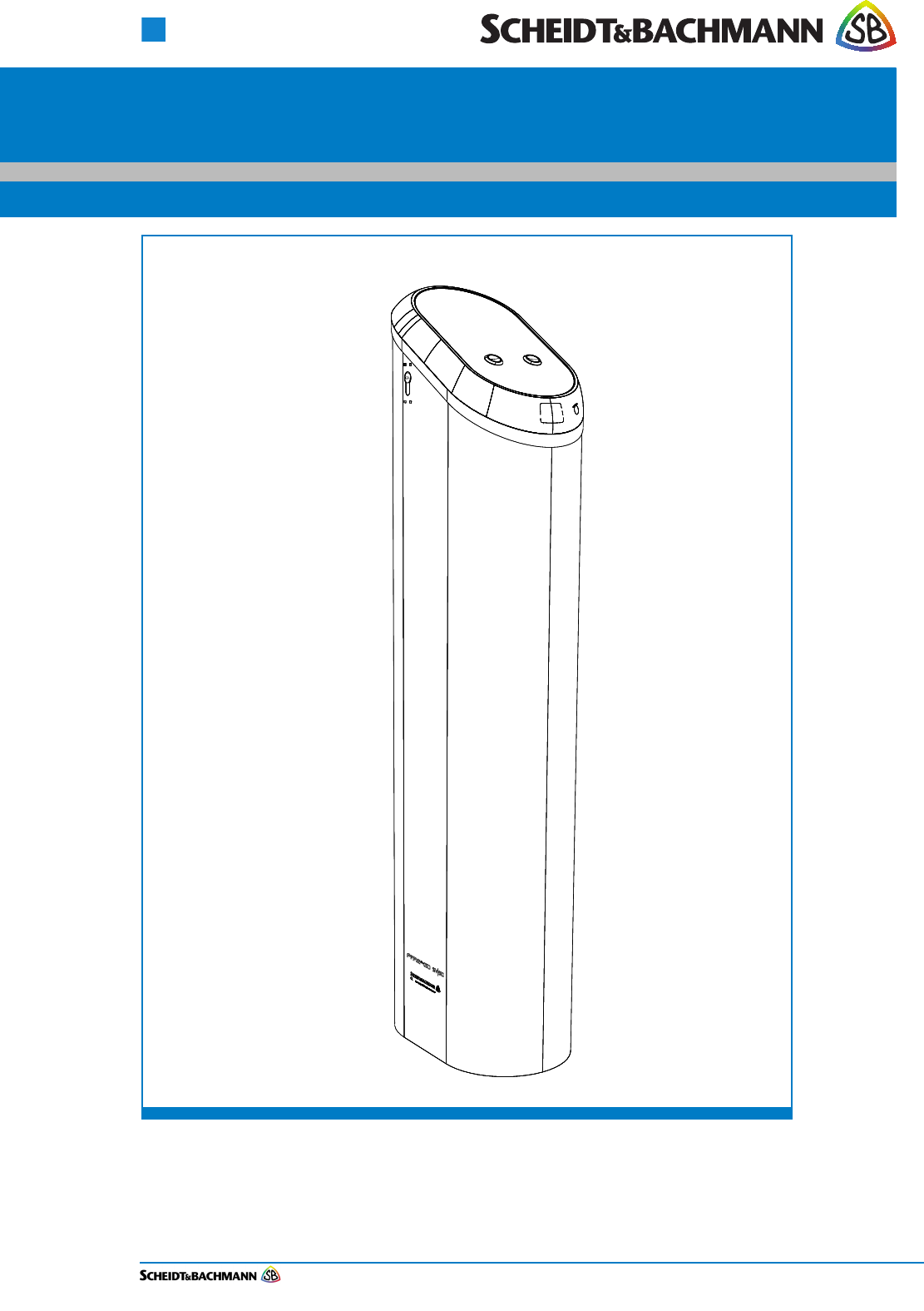
The SV|51 Station Platform Validator is a device with read and write capabilities
with contactless smartcards. The SV|51 will be floor mounted.
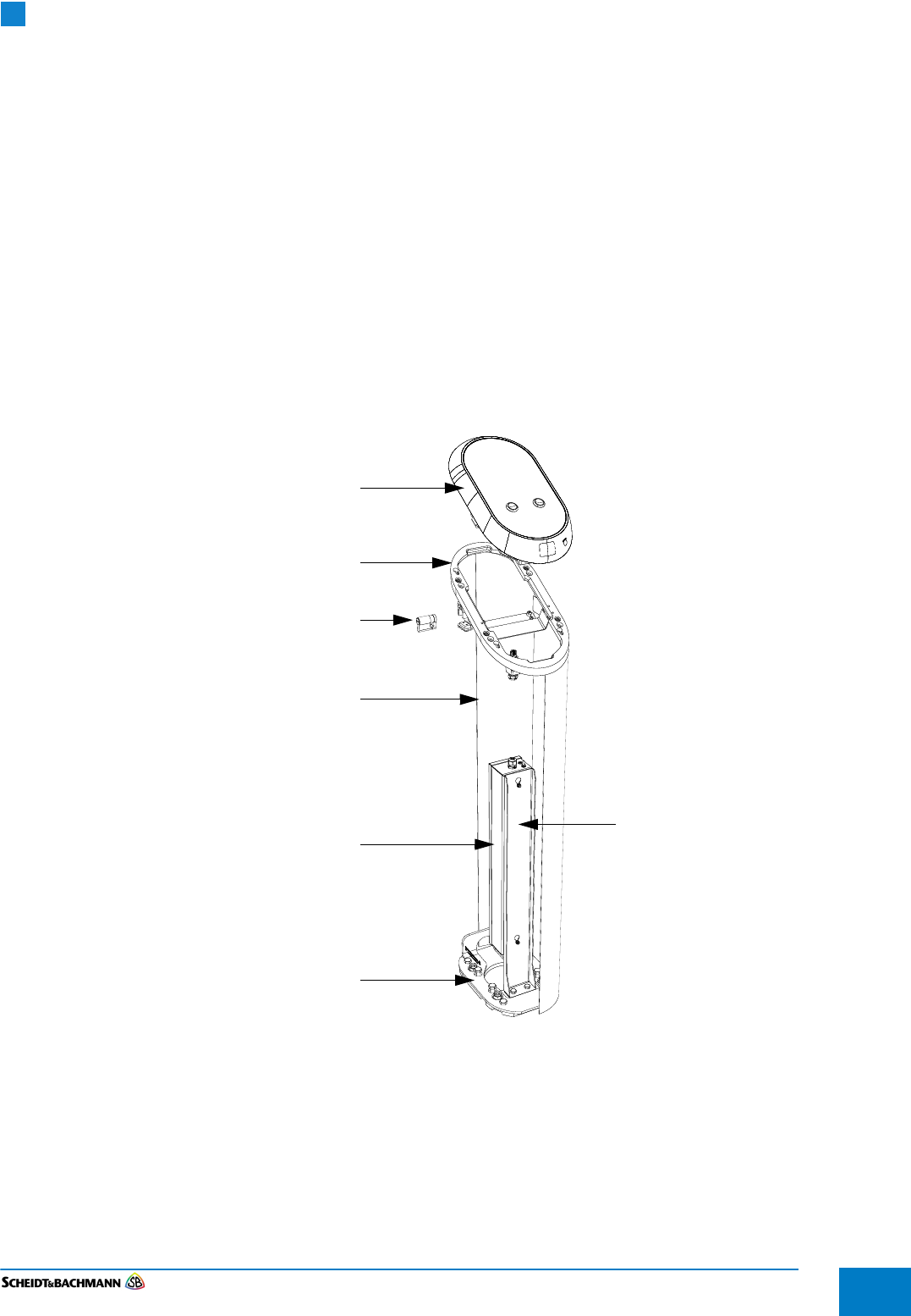
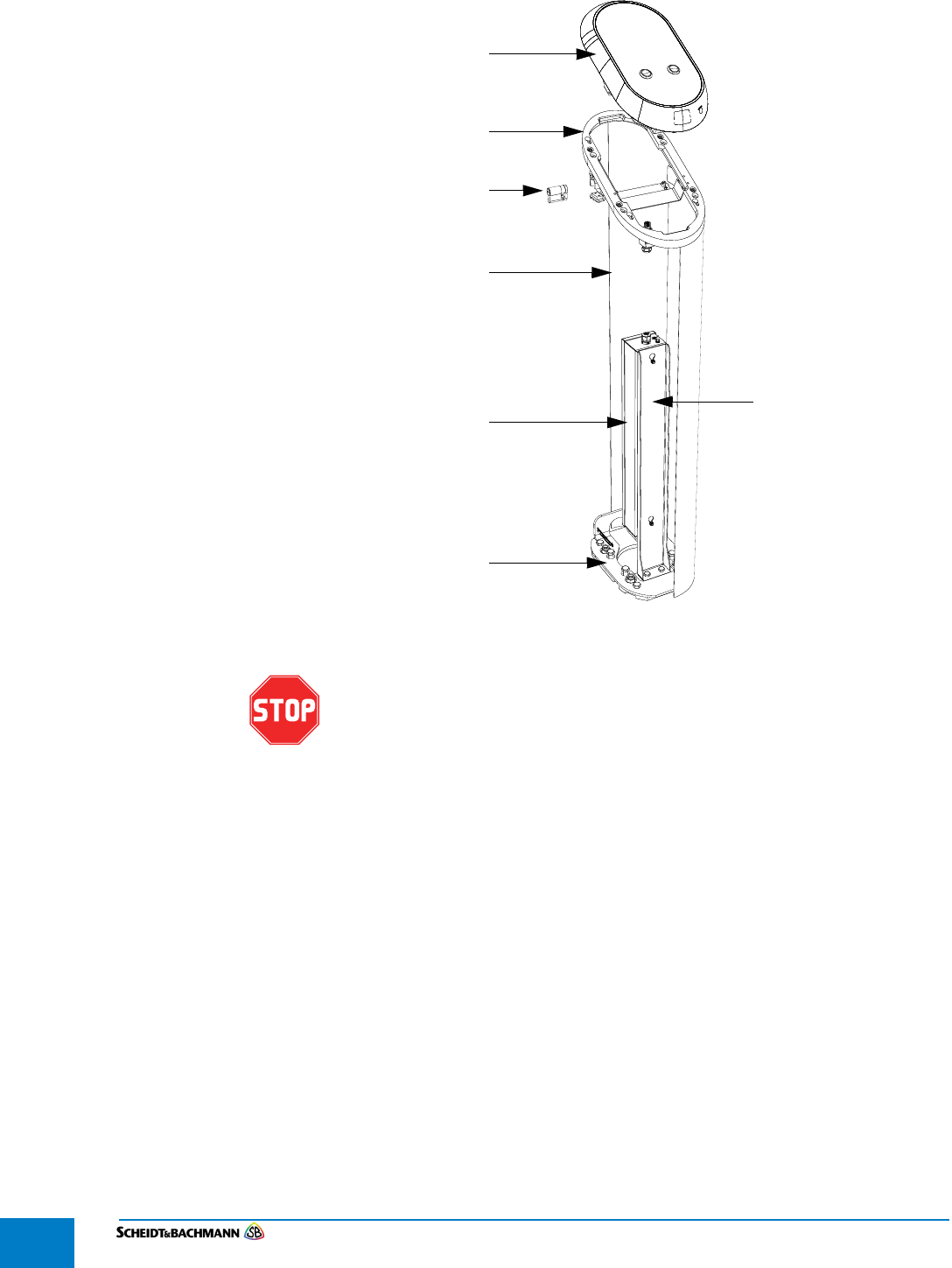
1.1.1 Components The SV|51 is comprised of six main components as shown below (Figure 5):
Base Plate
Power Supply
Stainless steel column with a welded mounting plate at the bottom
Adapter Ring
SV|51 Main Unit
Lock
Figure 1-1 Components
1.2 Overview The Station Fare Transaction Processor Repair and Maintenance Manual
(RMM) provides complete, detailed instructions for operating, maintaining, and
troubleshooting the Station Fare Transaction Processor. Comprehensive charts,
tables, graphs and other diagrams provide a technical document that is easy to
use and understand.
SV|51 Main Unit
Lock
Stainless steel
column
Power Supply
Adapter ring
Base Plate
Power supply mount

Chapter 1
Introduction and Safety
Edit: Stevens Art.#.: 86 —--, Version: 1.02 Datum:13.12.2017
1-6
Full documentation that would be needed by maintenance personnel is available
through Scheidt & Bachmann. The manual assumes that comprehensive repair
procedures will be performed by fully trained contractor technicians.
This manual reflects Scheidt & Bachmann’s commitment to providing our cus-
tomers with comprehensive technical documentation, along with training guide-
lines to augment our customer training program.
PLEASE READ THIS MANUAL AND ALL REFERENCED DOCUMENTS
CAREFULLY BEFORE ATTEMPTING TO INSTALL THIS AFC EQUIPMENT.
FAILURE TO FOLLOW THE INSTRUCTIONS IN THIS MANUAL AND THE
INSTRUCTIONS OR NOTES IN THE INSTALLATION DRAWINGS MAY
CAUSE INJURY TO YOURSELF OR DAMAGE TO THE EQUIPMENT AND
MAY ULTIMATELY COMPROMISE THE OPERABILITY OF THE
EQUIPMENT!
All Automated Fare Collection (AFC) equipment is TÜV-SÜD-NRTL listed. To
continue to be compliant with TÜV-SÜD-NRTL requirements, please note that
the following items need to be performed during installation:
The equipment will remain TÜV—SÜD-NRTL compliant only if the mounting and
wiring are also TÜV-SÜD-NRTL compliant. Please take great care during instal-
lation to comply with TÜV-SÜD-NRTL and NEC requirements.
Ensure compliance with all Safety Regulations and Safety Recommendations.
Although this manual has been prepared with great care, some information may
seem unclear. If so, please feel free to contact us with your remarks or ques-
tions.
Scheidt & Bachmann USA
781 272-1664
DISCLAIMER
Scheidt & Bachmann USA INC. IS NOT LIABLE FOR INJURIES TO ANY
PERSON OR DAMAGE TO THE EQUIPMENT RESULTING FROM FAILURE
TO COMPLY WITH THE MANUFACTURER’S INSTRUCTIONS OR
DOCUMENTATION. THIS DISCLAIMER INCLUDES ALL THIRD PARTY
DOCUMENTATION PREPARED BY OEMS AND PROVIDED AS A
COURTESY BY Scheidt & Bachmann USA INC. TO ITS CUSTOMERS.
FAILURE TO FOLLOW MANUFACTURER’S INSTRUCTIONS MAY
INVALIDATE ANY OR ALL WARRANTIES, EXPRESS OR IMPLIED.
NOTE: NOT ALL OF THESE WARNING LABELS OR HAZARDS MAY EXIST IN ALL
AFC DEVICES. ONLY THOSE LABELS THAT APPLY TO THE STATION
FARE TRANSACTION PROCESSOR, AND ARE REQUIRED TO MEET UL
CERTIFICATION REQUIREMENTS, WILL BE FOUND IN THE STATION
FARE TRANSACTION PROCESSOR. BE CAUTIOUS AND OBSERVANT,
AND LOOK FOR SUCH WARNING LABELS AND POTENTIAL HAZARDS.
ANY TECHNICIAN OR PERSON ACCESSING THE INTERIOR OF ANY AFC
DEVICE SHOULD USE COMMON SENSE AND EXERCISE EXTREME CAU-
TION.
1.3 Safety
Features
Safety engineering is an integral part of Scheidt & Bachmann’s designs. Mainte-
nance technicians must perform maintenance and repair in accordance with
industry safety standards including Federal, Provincial, and Local codes and
regulations.

Chapter 1
Introduction and Safety
Edit: Stevens Art.#.: 86 ——, Version: 1.02 Datum:13.12.2017 1-7
Close attention to proper safety precautions is of the utmost importance. Com-
ponents should be installed, maintained, and repaired only by trained, qualified
personnel using reasonable care. Improper installation, maintenance, or repair
procedures may damage the machine or cause serious personal injury or death.
The following pages provide detailed information on safety precautions that
must be observed when working on AFC Systems. This information should be
carefully read and thoroughly understood before performing routine mainte-
nance or attempting to troubleshoot or repair the machine.
It is the responsibility of the maintenance agency to ensure that the safety
instructions in this manual are read, understood, and implemented by properly
trained maintenance and service technicians. All other persons who work with
the internal systems of any AFC systems should also be trained in safety.
Topics covered in this section include:
1.1 General Safety Guide
1.4 Protective Equipment
1.5 Special Tools
1.2 Use of Symbols in Manual
1.6 Machine Safety Labels
In addition to the safety features listed in this section, which includes
specific UL safety labels, additional UL requirements are shown in these
three drawings included in Chapter 7: Electrical Installation Mains,
Electrical Installation Ethernet, and Mounting Possibilities.

Chapter 1
Introduction and Safety
Edit: Stevens Art.#.: 86 —--, Version: 1.02 Datum:13.12.2017
1-8
1.1 General
Safety Guide
This chapter provides the technician with the safety information necessary to
avoid personal injury or equipment damage. Only qualified, trained technicians
using reasonable care should perform maintenance or repair. As with any
mechanical system, the AFC components can pose certain safety hazards. The
following guidelines must be followed when working on the mechanical systems
of any AFC Systems or Components.
Only competent, qualified technicians trained by Scheidt & Bachmann should
service this machine.
Service technicians must read and understand all operating and service
instructions.
Turn electrical power off before opening any electrical enclosure.
Do not operate the machine with the cover of any enclosure, or the guard or
covers over any mechanism, removed.
Due consideration should be given to any safety regulation applicable to the
particular location in which the machine is operating.
Do not turn on power to the machine when components are disconnected.
The machine must not be used for any purpose other than that for which it
was designed and approved by Scheidt & Bachmann.
When servicing or repairing the machine, all machine control panels must be
tagged in compliance with OSHA Lockout/Tagout procedures to indicate that
machine should not be operated.
1.4 Protective
Equipment
The technician should use care when working with solvents and other cleaning
agents that may be abrasive or have a tendency to cause irritation to the skin or
eyes. Read all labels carefully and follow instructions for the use of gloves when
working with chemical fluids.
When using cleaning agents such as fluids or pressurized air, safety glasses
must be worn to prevent eye damage.
1.5 Special Tools There are no special tools required to ensure the safety of the service techni-
cian. However, ESD (Electrostatic Discharge: see paragraph 1.5.8) protection is
required for all procedures involving contact with electrostatic sensitive printed
circuit boards. The use of a standard ESD Safety Wrist Strap is required when
working with electrostatic sensitive printed circuit boards.
Chapter 1
Introduction and Safety
Edit: Stevens Art.#.: 86 ——, Version: 1.02 Datum:13.12.2017 1-9
1.2 Use of
Symbols in
Manual
Symbols for cautions and warnings are used frequently throughout this manual.
Each symbol appears on the left side of the page with the associated text printed
to the right.
There are several different types of symbols that indicate varying levels of safety
hazards. Detailed information on each symbol is provide in this chapter.
It is vital that the technician understand and follow all safety warnings, cautions
and information guidelines when working on AFC Systems.
1.5.1 Warning
Symbol
The Warning Symbol indicates a potential for serious damage to the equipment
or serious injury to the maintenance or service technician. Extreme care should
be used when performing procedures that are preceded by this symbol.
This symbol indicates a WARNING. A detailed description of the particular
hazard will appear next to the symbol in bold, italic print.
1.5.2 Caution Symbol The Caution Symbol indicates a potential for damage to a particular part or func-
tion of the machine. Reasonable care should be used when performing proce-
dures preceded by this symbol.
This symbol indicates a CAUTION. A detailed description of the particular
hazard will appear next to the symbol in bold, italic print.
1.5.3 Information
Symbol
The Information Symbol indicates special information that could be important for
protecting a particular part or function of the machine. Reasonable care should
be used when performing procedures that are preceded by this symbol.
This symbol indicates that more INFORMATION follows. A detailed
description of the particular hazard will appear next to the symbol in bold,
italic print.
1.5.4 Example
Symbol
The Example Symbol precedes an example of a function. The text or illustration
explains one possible function. This explanation applies to all other functions of
the same kind.
This symbol indicates that an EXAMPLE follows.
1.5.5 Finger Tip
Maintenance
Symbol
The Finger Tip Symbol indicates that no tools are required to perform the task
described. Reasonable care should be used when performing procedures that
are preceded by this symbol.
This symbol indicates a FINGER TIP MAINTENANCE action. A step-by-
step description of the task will appear next to the symbol in bold, italic
print.
1.5.6 Tools Symbol The Tools Symbol indicates that tools are required to perform the task described.
Reasonable care should be used when performing procedures that are pre-
ceded by this symbol.
Chapter 1
Introduction and Safety
Edit: Stevens Art.#.: 86 —--, Version: 1.02 Datum:13.12.2017
1-10
This symbol indicates a TOOL is required to perform the task described in
the text.
1.5.7 Electrical
Hazard Symbol
The Electrical Hazard Symbol indicates the potential for serious damage to the
machine caused by electrical voltage surges or serious injury to the service tech-
nician caused by electrical shock. Extreme care should be used when perform-
ing procedures preceded by this symbol.
This symbol indicates possibility of ELECTRICAL HAZARD. A detailed
description of the particular hazard will appear next to the symbol in bold,
italic print.
1.5.8 Electrostatic
Discharge
Symbol
The Electrostatic Discharge Symbol indicates the potential for serious damage
to the printed circuit boards or other Electrostatic Discharge (ESD) sensitive
devices in the machine. Extreme care should be used when performing proce-
dures preceded by this symbol. The technician should wear a grounding strap
and use the proper techniques associated with handling printed circuit boards or
other ESD sensitive devices.
This symbol indicates an ESD HAZARD. A detailed description of the
particular hazard will appear next to the symbol in bold, italic print.
1.5.9 Hot Hazard
Symbol
The Hot Hazard Symbol indicates the danger for serious burns caused by sur-
faces within the machine that may be extremely HOT to the touch. Hot surfaces
can cause serious injury to the service technician. Extreme care should be used
when performing procedures preceded by this symbol.
This symbol indicates a RISK OF BURNS. A detailed description of the
particular hazard will appear next to the symbol in bold, italic print.
1.5.10 Maintenance
Cycle Symbol
The maintenance cycle symbol indicates the required maintenance cycles
described in the subsequent part of the manual. An example is shown below.
Time is indicated by month or by quantities of coins or tickets.
1.6 Machine
Safety Labels
The typical AFC device has safety labels on some internal components to alert
service technicians and other personnel that a safety hazard may exist when
working on certain machine subassemblies. Not all safety labels may apply to
service operations on every subassemblies.
A series of different labels is used within the machine. The following paragraphs
describe these labels and note the location within the machine where they will be
found. It is important to read and understand this information thoroughly.
Preventive maintenance cycle: Every 3 months
Chapter 1
Introduction and Safety
Edit: Stevens Art.#.: 86 ——, Version: 1.02 Datum:13.12.2017 1-11
1.6.1 Labels On
Inside Of Most
AFC
Enclosures
There are several labels used on the assemblies located on the inside of the typ-
ical AFC device enclosure. These labels and their meanings are described
below.
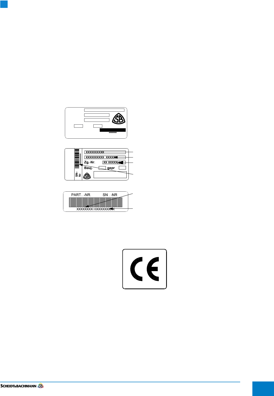
1.6.1.1 Model Number
Labels
The Model Number Label shown in Figure 1-2 is typically found inside the AFC
device on the floor of the enclosure and also on all main modules. There are
three different types of labels used. This label indicates the drawing or part num-
ber as well as the serial number. The index in brackets after the drawing number
or part number indicates the hardware release. It will be changed in conjunction
with hardware updates, i.e. index “A” will become index “B.”
Figure 1-2 Model Number Labels
1.6.1.2 CE Label The CE label shown in Figure 1-3 appears on the backside of the device.
Figure 1-3 CE Label
1.6.1.3 FCC License
Label
The FCC License label shown in Figure 1-4 appears on the backside of the
device.
Part number
Serial number
Label for products
Label for products
S&B GmbH (option 1).
Label for products
S&B GmbH (option 2).
Part name
Additional Info.
Part number
Serial number
manufactured by
with index manufactured by
S&B USA, Inc.
manufactured by
xxxxxxxxx
xxxxxxx ( )
xxxxxxxxxx
Description
Part No.
Serial No.
Year
Made by:
Scheidt & Bachmann USA
Tested
* *
Chapter 1
Introduction and Safety
Edit: Stevens Art.#.: 86 —--, Version: 1.02 Datum:13.12.2017
1-12
Figure 1-4 FCC-License
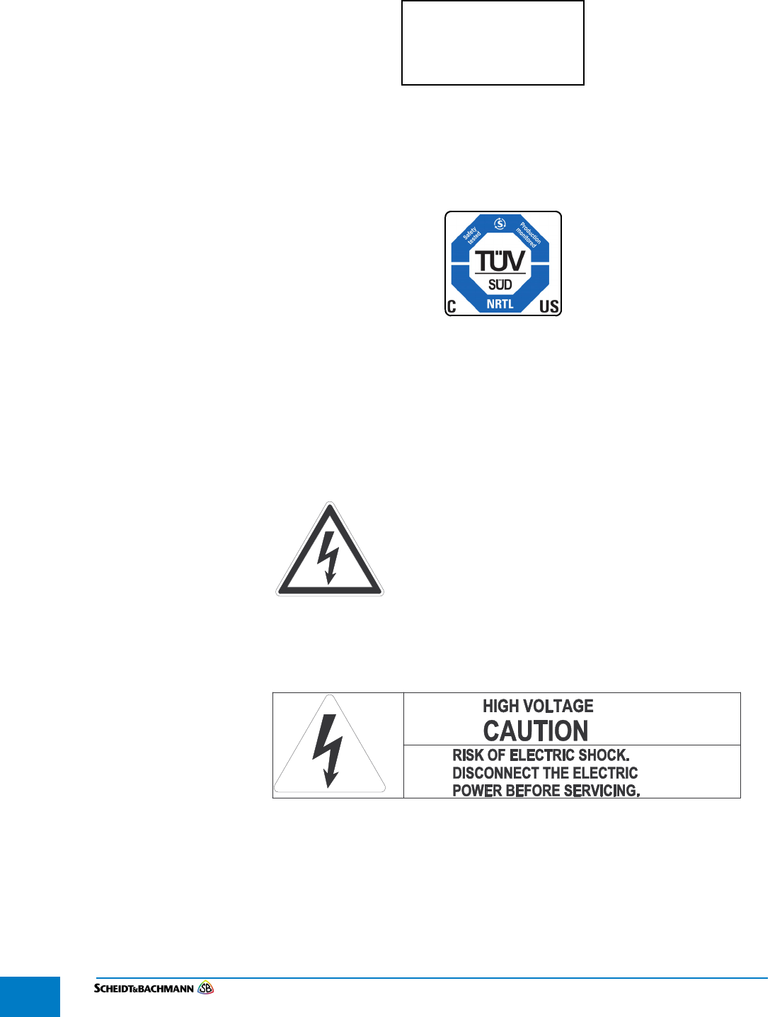
1.6.1.4 TÜV SÜD
NRTL Label
The TÜV-SÜD-NRTL label shown in Figure 1-5 appears on the backside of the
device.
Figure 1-5 NRTL-Label
1.6.1.5 Electrical
Hazard Label
The Electrical Hazard label shown in Figure 1-6 appears on or near certain
components located inside the device door and/or enclosure. The label is used
to indicate an electrical hazard such as risk of electrical shock that can cause
serious injury to the technician or observer that fails to observe the warning.
Figure 1-6 Electrical Hazard Label
Special Electrical Hazard Labels are shown in Figure 1-7 and Figure 1-8.
Figure 1-7 located on the customer display inside of the frame of the device.
Figure 1-7 Electrical Hazard Label on the back of most Customer Displays
FCC ID: O5K-NVP
IC: 8312A-NVP
HVIN:SV51
Chapter 1
Introduction and Safety
Edit: Stevens Art.#.: 86 ——, Version: 1.02 Datum:13.12.2017 1-13
Figure 1-8 Electrical Hazard Label used for the MEM
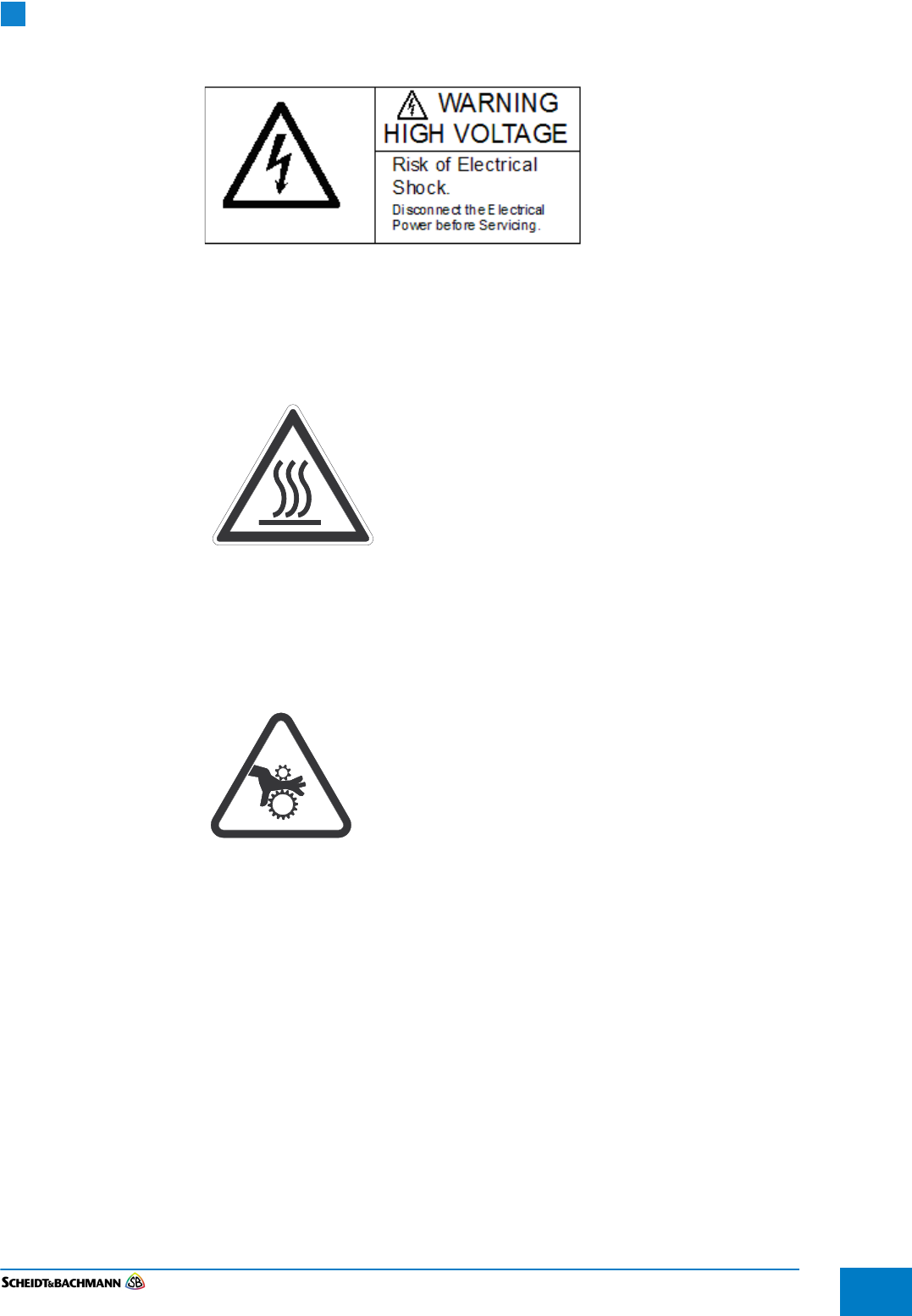
1.6.1.6 Hot Surface
Label
The Hot Surface label shown in Figure 1-9 below is used on the heater/blower
unit to indicate the possibility of burns when touching the heater/blower unit. This
label can also be found where other heat or burn hazards may exist.
Figure 1-9 The Hot Surface Label
1.6.1.7 Hand
Entanglement/
Rotating Gears
Label
The hand entanglement/rotating gears label is used to indicate an entanglement
hazard (such as the risk of crushing or cutting fingers) that can cause serious
injury to the technician or observer.
Figure 1-10 The Hand Entanglement/ Rotating Gears Label

Chapter 1
Introduction and Safety
Edit: Stevens Art.#.: 86 —--, Version: 1.02 Datum:13.12.2017
1-14
THIS PAGE INTENTIONALLY BLANK.

Chapter 2
Glossary
Edit: Stevens Art.#.: 86 ——, Version: 1.02 Datum:13.12.2017 2-15
Chapter 2 Glossary
2.1 Glossary of
Terms and
Abbre-
viations
Many terms and abbreviations are used to describe Fare Collection Equipment.
Some are Automated Fare Collection (AFC) industry standard terms, some are
application-specific, such as networking and telecommunications terms, and
some are unique to the customer’s system.
NOTE: The term “TVM” as used in this glossary is synonymous with the term
“FVM” (Fare Vending Machine). The term “TSM” as used in this glossary
refers to any AFC device that sells Tickets. It is an all-inclusive term. TVM
and TSM are standard AFC-industry acronyms. The SSK is a variation of a
TVM.
NOTE: This is a comprehensive glossary that may include items or terms not
used by your transit agency.
A
A See “Ampere”.
AC See “Alternating Current”.
Access Level Individual users of a computer system have
specific access rights that regulate what they
can view or modify. Access rights are organized
into groups, which are called Access Levels.
ADA See “Americans with Disabilities Act”.
AFC Automatic Fare Collection
Alarm Event An alarm event is generally defined as the
unauthorized opening of an AFC machine.
Alarm System A combination of sensors in an AFC machine
that indicates when the unit has been opened
without authorization. May trigger either an
audible or silent alarm, depending on the
machine design.
Alternating Current An electrical current that continuously changes
polarity or direction of flow, usually 50 or 60
times per second
Americans with Disabilities
Act (ADA)
The federal law mandating facility and equip-
ment accessibility requirements for persons
with disabilities.
Ampere A unit of measure of electrical current, the cur-
rent produced by applying one volt to a circuit
with a resistance of one ohm.

Chapter 2
Glossary
Edit: Stevens Art.#.: 86 —--, Version: 1.02 Datum:13.12.2017
2-16
ANSI American National Standards Institute
Application Server NT-based server which runs the Central Com-
puter System Application processes
APTA American Public Transportation Association
ASCII American Standard Code for Information Inter-
change
Audio Speaker A speaker that broadcasts messages in the lan-
guage of choice with content similar to the mes-
sage on the customer display.
AWG American Wire Gauge, a measure of the cross
section of a wire.
B
Bank Account No. Bank account number of an employee
Bank ID No. Bank identification number of an employee
Barcode A barcode is used to encrypt data into a series
of vertical bars (universal product code [UPC]).
It identifies various modules within an AFC
device such as a ticket roll.
Barcode Scanner The Barcode Scanner is a handheld scanner
used to read barcodes (e.g. on replacement
components).
Battery Pack The Battery Pack module supplies 39 VDC if
AFC machine main power is lost.
Bitmap Bit-oriented graphics
Blower Also referred to as a “fan,” the blower cools the
Central Processing Unit (CPU) in the ECU.
Boot Loading of the operating system into the RAM
Byte 1 Byte = 8 Bit
C
CAD/AVL Computer Aided Dispatch/Automatic Vehicle
Locator
Card A credit, debit, stored value, or “smart” card
Card Reader See “Credit Card Reader”.
CCS See “Central Computer System”.
Central Computer System
(CCS)
Centralized company file server that collects
and distributes operating and system fare col-
lection data. The CCS serves all AFC system
connected machines and devices.
Command Instruction to initiate a special transaction

Chapter 2
Glossary
Edit: Stevens Art.#.: 86 ——, Version: 1.02 Datum:13.12.2017 2-17
Command Codes See “Service Command”.
Commuter Rail Server A computer system that acts as a data conduit
between the Central Computer System (CCS)
and the Station Controllers at commuter rail
stations.
COTS “Commercial Off The Shelf “equipment
CPU Central Processing Unit
CRC Cyclic Redundancy Check. Check sum of the
content of the file.
Customer Display The Customer Display is a part of the user
interface. In some AFC machines, it may
include a touch screen.
Customer Specific Value A data field in which the customer is able to
store individualized information.
D
Database A database is an accumulation of individual
pieces of information that are related to each
other.
Database Server The Database Server is the CCS hardware and
software system on which the database is
located.
DC Direct Current
DCM Data Control Module; a flash card used to
update equipment in the field.
Device Type Device type is a term that refers to categories of
AFC equipment, such as FVMs, TOMs, Fare
Gates, MEMs, etc.
Download The process of sending information from a host
to a client, enabling client data to be updated.
Driver Software interface which connects devices to
the operating system.
DTE Diagnostic and Test Equipment
E
Electrostatic Discharge
(ESD)
The Electrostatic Discharge symbol indicates
the potential for serious damage to the printed
circuit boards or other Electrostatic Discharge
(ESD) sensitive devices in the machine.
Grounding precautions must be followed when-
ever this symbol appears.
Element.h The element.h file defines elements in service/
statistic printouts.

Chapter 2
Glossary
Edit: Stevens Art.#.: 86 —--, Version: 1.02 Datum:13.12.2017
2-18
Error Codes Also called an error message, which is gener-
ated automatically when a particular set of
abnormal conditions occurs. Error information
concerning a system fault or equipment mal-
function can be viewed on the Customer Dis-
play, Service Terminal Display, or on a printed
report.
Error Message See “Error Code”.
ESD See “Electrostatic Discharge”.
Event Every action that occurs at or in the TSM is
defined as event.
Exchange Factor Factor needed to convert different currencies.
F
FCC Labels Federal Communications Commission (FCC)
labels that identify the license for the transpon-
der identification system. These labels are
located near each transponder, such as on the
Additional Coin Magazine connection board, in
the Coin Magazine Drawer and beside the Coin
Vault.
File Transfer Protocol
(FTP)
The Internet’s file transfer protocol. FTP, which
has been used for more than two decades, is a
standard protocol for accessing files on servers
all over the world.
Filter A Filter selects data under special criterion.
Firmware Computer programs and data loaded into read-
only memory that cannot be modified by the
computer during normal operation and that is
not erased by loss of power.
Flash Card The Flash Card is a memory storage module
(PCMCIA) used for AFC machine initialization
and backup storage.
FTP See “File Transfer Protocol”.
FVM See “Fare Vending Machine”.
G
GHz GigaHertz — a unit of measure of electrical fre-
quency equal to one thousand million (1012)
Hertz (cycles per second).
Graphical User Interface The panel and components through which the
customer interacts with the machine.
GUI See “Graphical User Interface”.

Chapter 2
Glossary
Edit: Stevens Art.#.: 86 ——, Version: 1.02 Datum:13.12.2017 2-19
H
HD Abbreviation for Hard Disk
Heater The heater is located in the bottom of the AFC
machine housing. It provides heat when acti-
vated by a thermal sensor. Also, see Heater/
Blower Unit (HBU).
Heater/Blower Unit The Heater/Blower Unit (HBU) is activated by
an environmental temperature sensor, which is
typically located above the ECU Main Com-
puter. When activated, the HBU blows cool or
warm air (depending on the ambient tempera-
ture) over the interior of the device.
Hexadecimal Numeric system with base 16 (figures from 0 to
15).
HICO Type of write/read head with high field strength.
Hz A unit of measure of electrical frequency, equal
to one cycle per second.
I
I/O Abbreviation for input/output
ID Abbreviation for “Identification Number”
ID Reader Device that reads IDs from magnetic strip
cards.
IEC International Electrotechnical Commission
IEEE Institute of Electrical and Electronic Engineers
Intrusion Alarm In most AFC machines, the intrusion alarm,
which may be audible or silent, monitors the
outer door. The alarm is triggered when an
attempt is made to force open the outer door.
The alarm also triggers when too much time
elapses before entering the security code or
inserting the cylinder lock. Alarm conditions are
also reported to the CCS, which then notifies
designated individuals or parties.
ISDN See “Integrated Services Digital Network”.
ISO International Standards Organization
K
KB Kilobyte (one thousand bytes, where 1 byte
equals 8 bits)
Key Pad See “PIN-pad”.

Chapter 2
Glossary
Edit: Stevens Art.#.: 86 —--, Version: 1.02 Datum:13.12.2017
2-20
Keyboard The keyboard is used by the user to enter data
into the system.
kHz KiloHertz – a measure of frequency equal to
one thousand Hertz (cycles per second)
L
LAN See “Local Area Network”.
Language Marker Displays the language the device is equipped
with.
LCD Liquid Crystal Display; see “LCD Display” .
LCD Panel Part of the FVM Customer Display.
LED Light Emitting Diode
LLRC See “Lowest Level Replaceable Component”.
LLRU See “Lowest Level Replaceable Unit”.
Lmk Check Value The Lmk Check Value images the check sum of
the host security module internal data.
Local Area Network (LAN) A group of interconnected computers located
within the same physical or geographical area
(e.g. within the same building or campus.) See
Wide Area Network.
Locking System See “Door Locks”.
Logical Stock The number used internally by the ticket control
software to identify a physical ticket. The “logi-
cal stock” number may differ from the actual or
“physical stock” number.
Login To get access the system, a login with ID and
password has to be completed.
Lowest Level Replaceable
Component (LLRC)
The most basic component that is normally
replaced in the field
Lowest Level Replaceable
Unit (LLRU)
The most basic unit or assembly that is nor-
mally replaced in the field
LRV Light Rail Vehicle
LUHN-Check The LUHN-check is an international standard
used to protect and proof credit/debit cards.
M
mA Milliampere – a unit of measure of electrical
current equal to one thousandth of an ampere.
An ampere is the current that flows through a
circuit of 1 ohm resistance with a voltage of 1
Volt applied.

Chapter 2
Glossary
Edit: Stevens Art.#.: 86 ——, Version: 1.02 Datum:13.12.2017 2-21
MAC Abbreviation for Message Authentication
Codes.
mAh An mAh is a milliampere-hour. It is one thou-
sandth of an ampere-hour and is commonly
used as a measure of charge in batteries. An
ampere-hour is the amount of energy charge in
a battery that will allow one ampere of current
to flow for one hour. The HCR battery is rated at
1200 mAh.
Main Circuit Breaker The Main Circuit Breaker, which is located in
the Power Connection Box, protects the system
against high current overload.
Main Module Main Application which controls the Central
Server Application.
Maintenance The action performed to prevent equipment
performance degradation or failure (preventive
maintenance) or restore the machine to an in-
service condition following a failure (corrective
maintenance).
Manipulation Alarm This alarm (siren) is activated if an attempt is
made to open the AFC machine without the
correct Personal Identification Number (PIN)
being entered within the designated time
period.
Manipulation Sensor This alarm is activated if an attempt is made to
open the Ticket Selling Machine without enter-
ing the correct Personal Identification Number
(PIN).
MAYFAIR Type of contactless write/read device for chip
cards
MB Megabyte – one million bytes, where one byte
equals 8 bits.
Mbps Megabits per second – one million bits per sec-
ond
MDT Abbreviation for Mobile Data Transporter.
MSHA Mine Safety and Health Administration
Multimedia Multimedia includes texts, pictures and audio
data.
The Main Computer The Main Computer is called the Electronic
Control Unit (ECU). In most AFC machines, the
ECU is located at the top of the cabinet and
may contain several expansion boards, such as
the Network Interface Board (NIB), Touch Con-
troller (for those that have a Touch Screen),
Sound Controller, I/O Board with Watchdog
Timer, KR-20 Board, and PCMCIA Adapter.

Chapter 2
Glossary
Edit: Stevens Art.#.: 86 —--, Version: 1.02 Datum:13.12.2017
2-22
N
NEMA National Electrical Manufacturers Association
Network Interface Card The Network Interface Card (NIC), installed in
the ECU, provides an Ethernet-based commu-
nications interface between an AFC machine
and the Local Area Network (LAN).
NIC Network Interface Card. Adapter for LAN
Noise Extraneous or interfering signals present on a
system caused by undesirable voltages or cur-
rents.
NWC Abbreviation for Network Controller
O
Occupational Safety and
Health Administration
(OSHA)
The United States Government regulatory and
oversight agency responsible for safety in the
workplace.
ODBC Open Data Base Connectivity
OEM Original Equipment Manufacturer
Oersted [Oe] 1 Oersted = 2.021268 Ampere per inch
Online/Offline If the TSM is connected to the Network, the net-
work state of the TSM is online, if the TSM is
disconnected, the state is offline.
Oracle Manufacturer of database software.
OSHA See “Occupational Safety and Health Adminis-
tration”.
P
Packet A unit of data routed between an origin and a
destination on any packet switching network.
These “chunks” of data are an efficient size for
routing.
Pass A magnetically encoded document that pro-
vides access to designated portions of the sys-
tem for a specified time period.
Password Every user has his own individual, classified
password that provides access to equipment.
Path The path describes the location of a data file.
PC Personal Computer – a mass-market class of
computer.
PCB Printed Circuit Board

Chapter 2
Glossary
Edit: Stevens Art.#.: 86 ——, Version: 1.02 Datum:13.12.2017 2-23
PCMCIA See “Personal Computer Memory Card Inter-
national Association”.
PCMCIA Personal Computer Memory Card International
Association. In the TSMs it is used as a flash
card for data transfer.
PDU See “Portable Data Unit”.
Permit A fare media element issued to a specific per-
son that identifies that person as authorized for
a reduced fare or adjustment. It is presented
when the person purchases a ticket or pays for
a ride.
Physical Stock An actual ticket in a roll or a magazine, with an
identifying sequential serial number printed on
it. The number may differ from the “logical”
number assigned by the ticket control software.
PIN Personal Identification Number.
PIN-Pad A PIN-pad is used by the customer to enter a
PIN code for various Credit/Debit Card opera-
tions. Also, as part of the ADA Compliance
Standard, the PIN-pad is used as an application
steering system for a blind patron.
Polling Data transmission initiated by inquiry.
Portable Data Unit A device used to extract data from a farebox for
uploading to the Garage Computer System.
Power Connection Board The Power Connection Board, located on the
back of the AFC machine housing, connects
power and delivers V.11 communication proto-
col to other microprocessor-based compo—
nents.
Power Connection Box The Power Connection Box is typically located
in the bottom right of the machine cabinet, but
may be mounted elsewhere in some machines
The unit routes 120 VAC Main Power to the
appropriate subsystems in the AFC machine.
Power Pack The NT-20 PP/3 Power Pack, a switching
power supply, plugs into the V.11 Power Con-
nection Board. The Power Pack converts
incoming 120 VAC to the various DC operating
voltages required for AFC machine compo-
nents and devices.
Powerfail Control A possible power failure is monitored by the
system
Primary Key Unique number (index) for a row in the data-
base

Chapter 2
Glossary
Edit: Stevens Art.#.: 86 —--, Version: 1.02 Datum:13.12.2017
2-24
Process System Interface The Process System Interface (PSI) is a soft-
ware process that both controls a hardware
component and interprets its state. This pro-
cess is specific to each hardware component.
The PSI, which is responsible for communica-
tion between separate software modules, oper-
ates independently of the operating system.
PROM Programmable Read-Only Memory
PSI See “Process System Interface”.
PSI number Address number of the device
Psiboot.bat Helpfile that starts different processes.
Q
QA/QC Quality Assurance/Quality Control
R
RAM Random Access Memory
RF Radio Frequency – a high frequency electrical
signal
RGB Video display color standard (Red, Green,
Blue)
ROM Read-Only Memory
RR Abbreviation for railroad
RTTE Radio and Telecommunications Terminal
Equipment Directive = RL 1999/EG) label iden-
tifies the radio license which is used for the
transponder reading transactions. The label is
located on the ACM (Additional Coin Magazine)
connection board.
RTU Remote Terminal Unit
S
S&B Scheidt & Bachmann-USA, Inc.
SBC-1 Scheidt & Bachmann Main Computer System.
Used in all S&B manufactured AFC machines
that require a computer. Also referred to as the
ECU (Electronic Control Unit.)
SCR See “Smart Card Reader”.
Service Command The Service Commands are entered into the
service terminal to initiate actions (e.g. prints
error codes, test tickets).

Chapter 2
Glossary
Edit: Stevens Art.#.: 86 ——, Version: 1.02 Datum:13.12.2017 2-25
Service Display See “Service Terminal Display”.
Smart Card Reader A device that reads the encoded value stored
on a smart card.
SONET See “Synchronous Optical Network”.
Sound Card The Sound Card, located in the ECU Main
Computer, provides voice messages for the
speaker and head phone jack, when available.
Speaker See “Audio Speaker”.
Stored Value Card A magnetically encoded ticket or smart card
with a specified dollar value that provides
access to designated portions of the system.
The value on the card is reduced with each
use.
Synchronous Optical Net-
work (SONET)
An ANSI standard for fiber optic networks.
System Devices that are integrated to perform a spe-
cific function, such as the Coin Processing Sys-
tem, Bank Note System, and so on.
System Support Record This file contains the rows of the screen “User
data”. It is downloaded to the Ticket Selling
Machines.
T
TCP/IP Transmission Control Protocol/Internet Proto-
col. The TCP is a reliable, connection-oriented
protocol that delivers, with virtually no error, a
byte stream originating on one machine to
another machine anywhere on the Internet.
The IP facilitates this transfer of data by placing
the bytes into packets that are easily transmit-
ted.
Temperature Sensor A thermal sensor, connected to the Tempera-
ture Regulator Board, that monitors the internal
temperature of the AFC machine housing.
When the temperature moves outside an
acceptable preset range (39.2 degrees F to149
degrees F), the Temperature Regulator Board
automatically turns off the machine.
Ticket A magnetically encoded plastic or paper docu-
ment used for entrance to the system and for
verification of payment. In general, this term
refers to the physical media, which can be
encoded as a stored value card or a time based
pass.

Chapter 2
Glossary
Edit: Stevens Art.#.: 86 —--, Version: 1.02 Datum:13.12.2017
2-26
Touch Controller Monitors the AFC Machine Customer Display
touch screen panel. Reports the results of data
input (screen touches) to the Application Soft—
ware. (Applies only to systems equipped with
Touch Screen devices.)
Touch Screen A Touch Screen is the component part of the
Customer/Agent Display that detects user input
by sensing a touch (or tap) on specific areas of
a surface wave-sensitive touch panel.
U
UL See “Underwriters Laboratories, Inc.”
Underwriters Laboratories,
Inc.
Underwriters Laboratories, Inc. – The testing
agency that certifies the safety and effective-
ness of specific electrical, fire, and security
equipment
UNIX Operating System.
Upload The process of sending data from the Client to
the Host Computer.
Username Every individual has a unique username that
identifies that person within the system.
V
VAC Volts Alternating Current
VDC Volts Direct Current
Version Group of data downloaded to the devices.
VGA Abbreviation for video graphics array
W
WAN See “Wide Area Network”.
Watchdog Timer The Watchdog Timer monitors the ECU CPU.
Should the CPU fall into a “dead” processor
loop, the Watchdog Timer instructs the CPU to
re-initialize the ECU and to reboot.
WAV-File File containing audio data.

Chapter 2
Glossary
Edit: Stevens Art.#.: 86 ——, Version: 1.02 Datum:13.12.2017 2-27
Wide Area Network (WAN) Spanning a country or continent, a Wide Area
Network is a communication network that
serves geographically separated areas and
locations.
Workstation PC within a network serving as a control, input,
or monitoring device.
Z

Chapter 2
Glossary
Edit: Stevens Art.#.: 86 —--, Version: 1.02 Datum:13.12.2017
2-28
THIS PAGE INTENTIONALLY BLANK.

Chapter 3
Declaration of Conformity
Edit: Stevens Art.#.: 86 ——, Ver. 1.02 Datum:13.12.2017 3-29
Chapter 3 Declaration of Conformity
3.1 Europe The device complies to the European Directive RED 2014/53/EU
The SV51 use the following radio frequencies in Europe
Characteristic Specification
Radio frequency:
Transmission power:
radio frequency:
Transmission power:
radio frequency:
Transmission power:
2400 — 2483.5 MHz
49 mW
5150-5775 MHz
45 mW
13.56 MHz
1.18 µW
Table 3-2 Operating Characteristics

Chapter 3
Declaration of Conformity
Edit: Stevens Art.#.: 86 ——, Ver. 1.02 Datum:13.12.2017
3-30
3.2 USA/
CANADA
NOTICE:
This device complies with Part 15 of the FCC Rules and with Industry Canada
licence-exempt RSS standard(s).
Operation is subject to the following two conditions:
1. this device may not cause harmful interference, and
2. this device must accept any interference received, including interference that
may cause undesired operation.
Le présent appareil est conforme aux CNR d’Industrie Canada applicables aux
appareils radio exempts de licence. L’exploitation est autorisée aux deux
conditions suivantes:
(1) l’appareil ne doit pas produire de brouillage, et
(2) l’utilisateur de l’appareil doit accepter tout brouillage radioélectrique subi,
même si le brouillage est susceptible d’en compromettre le fonctionnement.
NOTICE:
Changes or modifications made to this equipment not expressly approved by
(Scheidt&Bachmann) may void the FCC authorization to operate this equip-
ment.
Radiofrequency radiation exposure Information:
This equipment complies with FCC radiation exposure limits set forth for an
uncontrolled environment. It also complies with Industry Canada licence-exempt
RSS standard(s).
The radiated output power of the device is far below the FCC radio frequency
exposure limits. Nevertheless, the device shall be used in such a manner that
the potential for human contact during normal operation is minimized.
NOTE: This equipment has been tested and found to comply with the limits for
a Class B digital device, pursuant to Part 15 of the FCC Rules. These limits are
designed to provide reasonable protection against harmful interference in a res-
idential installation. This equipment generates, uses and can radiate radio fre-
quency energy and, if not installed and used in accordance with the
instructions, may cause harmful interference to radio communications. How-
ever, there is no guarantee that interference will not occur in a particular instal-
lation. If this equipment does cause harmful interference to radio or television
reception, which can be determined by turning the equipment off and on, the
user is encouraged to try to correct the interference by one or more of the fol-
lowing measures:
Reorient or relocate the receiving antenna.
Increase the separation between the equipment and receiver.
Connect the equipment into an outlet on a circuit different from that to which
the receiver is connected.
Consult the dealer or an experienced radio/TV technician for help.

Chapter 4
Installation and Initialization
Edit: Stevens Art.#.: 86 ——, Version: 1.02 Datum:13.12.2017 4-31
Chapter 4 Installation and Initialization
4.1 Overview The SV|51 installation instructions described in this chapter explain how to install
the devices, but do not prepare the machines for operation. Once installation is
complete, the installer should follow the SV|51 Initialization instructions.
The following information and instructions are provided for the installer of a
SV|51.
To avoid damage, deliver SV|51 equipment to the installation location in the
original packaging and Scheidt & Bachmann wrapping.
The SV|51 device is installed in locations chosen by the Transit Authority.
The SV|51 is a device that is able to read and write to contactless
smartcards.
NOTE: Placement of the SV|51s is at the discretion of the customer.
The SV|51 equipment is fragile. Handle with extreme care. Do not drop!
4.1.1 Components The SV|51 has six main components:
the base plate
the power supply
the stainless steel column with a welded mounting plate at the bottom
the adapter ring
the SV|51 Main Unit
the lock
Chapter 4
Installation and Initialization
Edit: Stevens Art.#.: 86 —--, Version: 1.02 Datum:13.12.2017
4-32
Figure 4-11 The Union Pearson Express Station Fare Transaction Processor
The safety labels shown in the section Machine Safety Labels must be
followed. Review them carefully before proceeding.SV|51
SV|51 Main Unit
Lock
Stainless steel
column
Power Supply
Adapter ring
Base Plate
Power supply mount
Chapter 4
Installation and Initialization
Edit: Stevens Art.#.: 86 ——, Version: 1.02 Datum:13.12.2017 4-33
4.3 Power For 120V/60Hz, power was read at 17.26W, apparent power at 17.62, current at
0.146A (146mA) and cos of 0.980. The power value is acceptable as it is less
than 17.5 W. At 230V/50Hz, power was read at 20.38 W, apparent power at
25.97VA, current at 0.113A (113mA) and cos of 0.785. These values are accept-
able. The estimated power consumption is in Table 4-3.
In the event of a power failure, the SV|51 will perform an orderly shutdown
based on the energy stored in local capacitors. When power is restored,
the SV|51 will start up and return to full operation without the need for
manual intervention.
Mode Power Consumption
Standby SV|51 ready to accept Smart Card Approximately 20W
Operational Smart Card processing and audio output Approximately 38W
Table 4-3 Power Consumption
Chapter 4
Installation and Initialization
Edit: Stevens Art.#.: 86 —--, Version: 1.02 Datum:13.12.2017
4-34
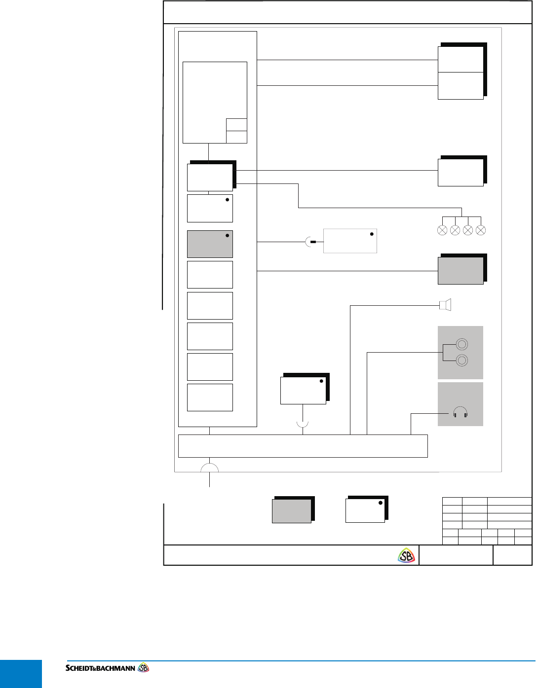
4.4 Block
Diagram
Figure 4-12 is the Block Diagram for the device.
Figure 4-12 Block Diagram SV|51 Page 1 of 2
09.06.17
86 35967 0 —
Block Diagram Platform Validator SV|51
09.06.17
EL
VKS
—.—.—
— — — —
/2
Technische Änderungen vorbehalten — Copyright Scheidt & Bachmann GmbH
Scheidt & Bachmann GmbH D-41238 Mönchengladbach
Bearb.
Gepr.
Norm
Datum Name
Zust.
Datum
Bearb.
Gepr.
Norm
Blatt/Anzahl
Der Inhalt dieses Dokumentes ist urheberrechtlich geschützt. The content of this document is protected by copyrights.
Diese Zeichnung wird bei Änderungen nicht berücksichtigt. This drawing is not to be considered for future revisions.
New Validation
Platform
03 73511
Speaker
1
CPU-Module
Trizeps VII
51 80442
09.06.17
EL
mSD
WiFi
SCR
2xSAM
Temperature
Sensor
Wake Up
by Clock
Hardware
Watchdog &
Reset
Onboard
Amplifier
Power Supply
5,7” LCD
640×480
LED
Backlight
Barcode
Scanner
Symmetric
DPC Antenna
03 77156
2x Pushbutton
Headphone
Jack
4 EMV LEDs
Connection Board
03 77525
RJ45 (IP54)
2xSAM
Backup
mSD Card
I2C Location
EEPROM
RGB 18 bit
PWM
Flat ribbon cable
I/O
RS232
I/O
I2C
USB 2.0
3,3V/5V
Power Limiter
Buffer Capacitors
Debug Interface
IMX6
ARM Cortex A9
800MHz
single core
1GB RAM
OPTIONAL Accesible via
service opening
Valid for
fix and optional
To pole
See page 2
Chapter 4
Installation and Initialization
Edit: Stevens Art.#.: 86 ——, Version: 1.02 Datum:13.12.2017 4-35
Figure 4-13 Block Diagram SV|51 Page 2 of 2
09.06.17
86 35967 0 —
Block Diagram Platform Validator SV|51
09.06.17
EL
VKS
—.—.—
— — — —
/2
Technische Änderungen vorbehalten — Copyright Scheidt & Bachmann GmbH
Scheidt & Bachmann GmbH D-41238 Mönchengladbach
Bearb.
Gepr.
Norm
Datum Name
Zust.
Datum
Bearb.
Gepr.
Norm
Blatt/Anzahl
Der Inhalt dieses Dokumentes ist urheberrechtlich geschützt. The content of this document is protected by copyrights.
Diese Zeichnung wird bei Änderungen nicht berücksichtigt. This drawing is not to be considered for future revisions.
Power Supply
LAN
Ethernet Cable with LAN and 36VDC
From SV51 Connection Box 10x
120 -230 VAC / 24 VDC
IP54 / NEMA3
120 — 230 VAC
To functional unit
see page 1
Variant 1
Power supply in SV51 pole
To functional unit
see page 1
Variant 2
Power from SV51 Connection Box 10x
Pole
Pole
2
09.06.17
EL
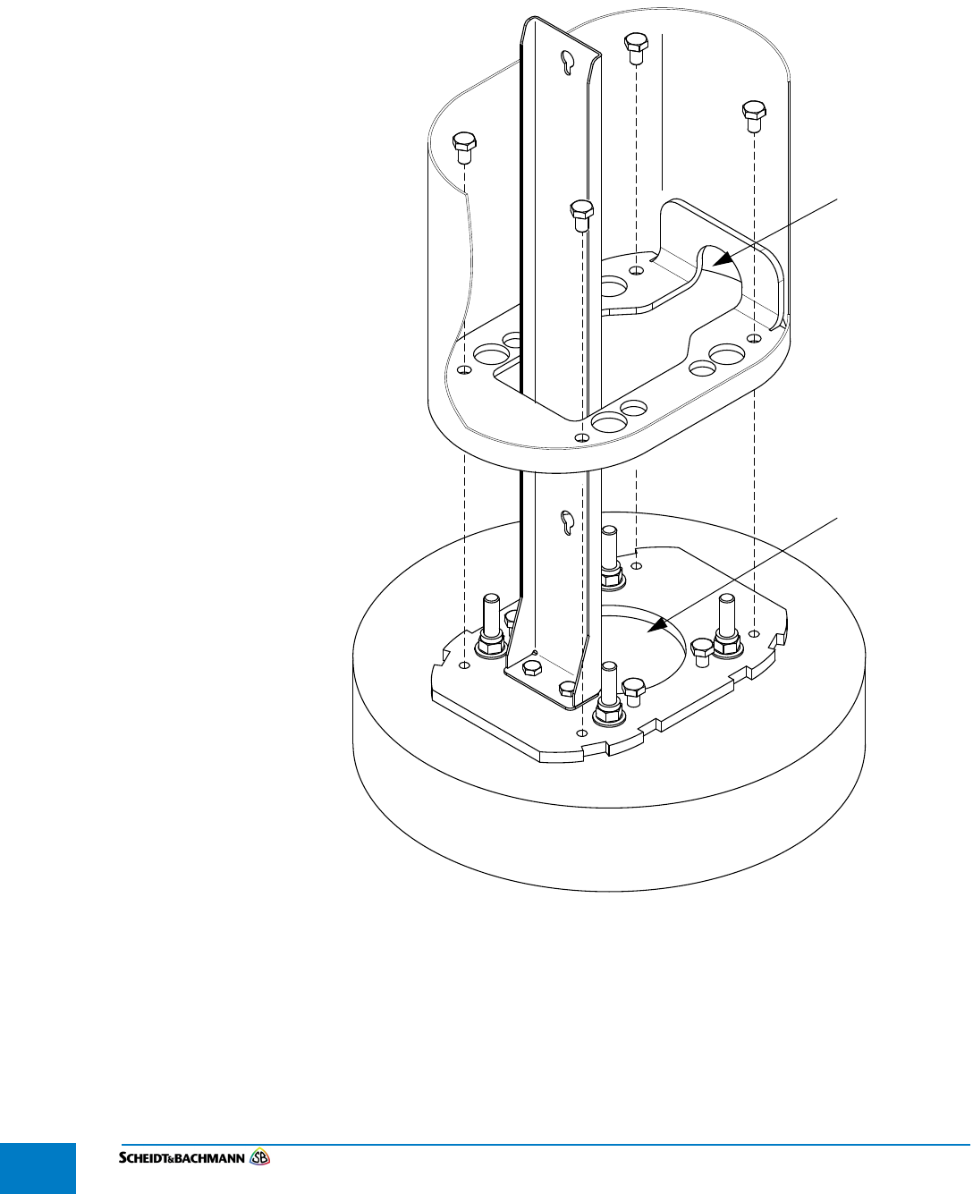
Chapter 4
Installation and Initialization
Edit: Stevens Art.#.: 86 —--, Version: 1.02 Datum:13.12.2017
4-36
4.5 Column
Variations/
Conduit Entry
Points
The SV|51 column provides two options for conduit entry ( Figure 4-14). The
first is at the bottom through the mounting plate. The second is through an open-
ing provided at the rear of the SV|51 column. The PRESTO customized opening
has a height of 70 mm and width of 30 mm with a rounded top.
Figure 4-14 SV|51 Conduit Entry Points
Rear Conduit
Entry Point
Bottom Conduit
Entry Point
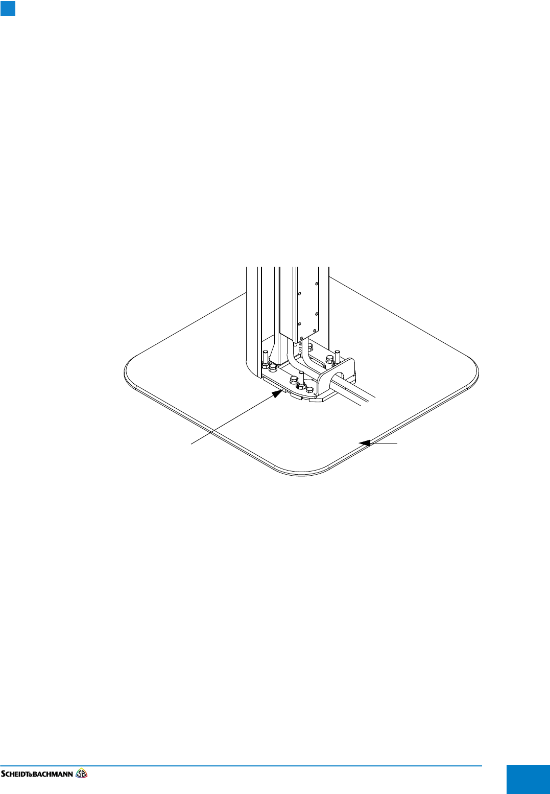
Chapter 4
Installation and Initialization
Edit: Stevens Art.#.: 86 ——, Version: 1.02 Datum:13.12.2017 4-37
4.6 Mounting
Options
There are two ways to install the base plate of an SV|51.
4.1.2 Drilling into
Concrete
This method assumes the Transit Agency prepared a concrete surface. Drilling
four holes into the concrete and securing four bolts in these holes allows these
bolts to hold the SV|51 in place. This method may utilize either the bottom or
side fed conduit entry options.
4.1.3 Adhesive
Option
The adhesive option utilizes a floor plate that has four pre-installed bolts. An
industrial strength adhesive secures the plate to the platform surface and the
bolts secure the SV|51 to the floor plate. This method must utilize the side
entry conduit option. For locations where drilling is not permitted a floor plate
will be used. The floor plate will be glued to the ground and is comprised of
two components fitted together. One is a 180 mm x 180 mm steel inlay for the
bolts. The other is a 700 mm x 700 mm hard coated aluminum plate
( Figure 4-15).
Figure 4-15 Mounting Plate for Adhesive Option
NOTE: By selecting the gluing mounting option a floor plate is utilized which may
pose a tripping hazard for SV|51 device users. The floor plate is designed
with a 45 degree beveled edge with a total height of 10mm. The final height
of the floor plate will be determined based on the type and amount of glue
applied to the mounting area to secure the floor plate to the ground.
NOTE: Ensure sable and even ground!
Base Plate Mounting Plate
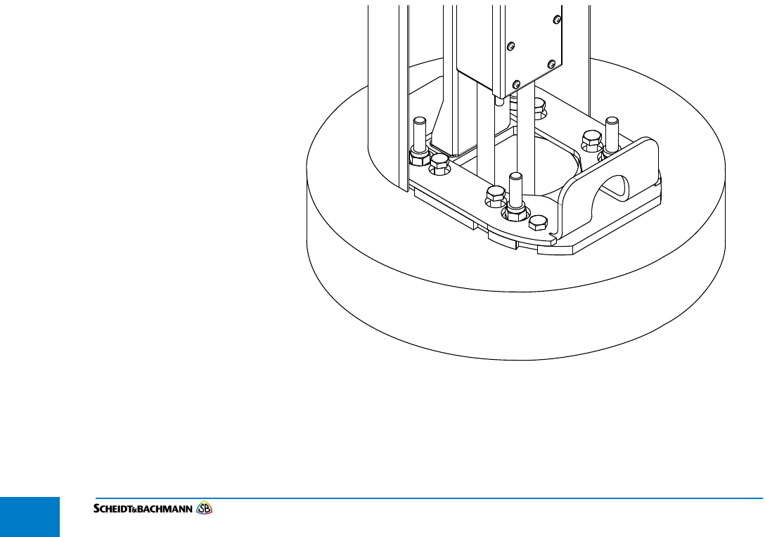
Chapter 4
Installation and Initialization
Edit: Stevens Art.#.: 86 —--, Version: 1.02 Datum:13.12.2017
4-38
4.7 Conduit
Requirements
Before SV|51 installation begins, the following requirements must be met:
Power and data cabling run in separate conduits to the identified installation
location. The size of the conduit at the installation location may be no larger
than 12.7 mm diameter.
The power cabling must run from a determined power source.
Data cabling run from the GO Transit network rack. The data cabling at the
SV|51 device end must be outdoor rated cat6 cable. Termination is to a clamp
inside the SV|51’s power supply. The ground at the identified installation
location must be level and free of obstructions.
Both the bottom and side fed conduit entry options are to use a 12.7mm water
tight flex conduit. This will allow the device installers on site to align the conduit
with the bottom openings of the power supply junction box inside the SV|51 col-
umn.
4.1.4 Side Conduit
Entry
Both power and data conduits must feed into the SV|51 column through the
entry point at the rear of the column ( Figure 4-15). The conduit lengths must be
a minimum of 300mm from rear entry point of SV|51 column. A minimum length
of 470mm of power cable and 770mm of data cable must be available from the
rear entry point of the SV|51 column.
4.1.5 Bottom Conduit
Entry
Both power and data conduits must feed into the SV|51 column through the hole
in the SV|51 baseplate ( Figure 4-16). The conduit lengths must be a minimum
of 130mm from bottom of SV|51 column. A minimum length of 300mm of power
cable and 600mm of data cable must be available from the bottom of SV|51 col-
umn.
Figure 4-16 Bottom Conduit Entry

Chapter 4
Installation and Initialization
Edit: Stevens Art.#.: 86 ——, Version: 1.02 Datum:13.12.2017 4-39
4.8 Installation Scheidt & Bachmann will provide one set of items listed in the Bill of Materials (
Table 4-4) with each SV|51.
4.1.6 Bill of Materials The items in Table 4-4 will be included as part of the SV|51 Bill of Materials.
4.1.7 Tools Required At a minimum, the installation of the SV|51 will require the following tools:
Cable Cutter.
Wrench with sockets for M8, M10, and M12 hexagonal screws/nuts.
Ratchet.
Two Extended Ratchet Sockets (1m) and (>= 23cm).
Bubble Level.
Sealing material for the conduit at entrance and terminal points of the power
supply.
SD Card Labeling Printer.
Keys.
Qty Part Name S&B p/n
1 SV|51 Validator 03 71656
1 Floor Plate (for glued down solution) 03 71688
1 Lock 86 33878
4 Collared Hexagon Nut M12 70 03705
4 Washer for M12
1 Power Supply Unit incl. cable with RJ45
connector
03 71274
1 Holder for power supply 5103485 03 71273
2 Screw for holder, M8 70 03058
2 Washers for M*
2 Screw for Power Supply 70 03661
4 M10 Hexagon Screw, optional if levelling is
required
70 03133
4 Screws for securing column to baseplate 70 01474
4 Screws for securing adapter ring to the
column
70 03072
1 Stainless Steel Column (Housing) 03 71705
1 Base Plate 03 71272
3 End sleeve power cable (optional, for
stranded power cables)
n/a
Table 4-4 Bill of Materials

Chapter 4
Installation and Initialization
Edit: Stevens Art.#.: 86 —--, Version: 1.02 Datum:13.12.2017
4-40
4.8.1 SV|51
Installation
Steps
The following steps demonstrate how to install a SV|51. It is assumed that the
conduit requirements have been met prior to the first installation step below:
Drilled Solution: four bolts should be permanently fixed into holes drilled
into the concrete as per the drilling pattern. The size of the bolts is M12. They
should extend out of the concrete between 40 – 70 mm. The installation
package includes 4 nuts for mounting the plate to the concrete.
Adhesive Solution: A floor plate pre-assembled with four bolts. The
installation shall utilize an adhesive to secure the floor plate to the ground.
There are only two minor differences in the installation steps for the two varia-
tions:
The glued solution is secured at the installation site by utilizing four bolts on
the floor plate, while the drilled solution is secured using four bolts drilled into
concrete.
The power and data cables can be fed through the bottom or side of the
SV|51 column for the drilled solution, while these cables must be fed through
the side of the SV|51 column for the glued solution.
4.1.8 Mounting the
base plate
The front side of the base plate can be distinguished by the two screw openings
in front of the conduit opening as shown in Figure 4-17. The front side would be
the closest side to the user if they were using the SV|51 front face.
4.1.8.1 Drilled
solution
Place the base plate on the concrete; ensure the four bolts pass through the
middle screw openings on the base plate.
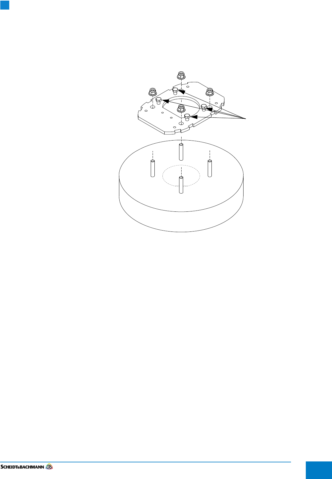
Chapter 4
Installation and Initialization
Edit: Stevens Art.#.: 86 ——, Version: 1.02 Datum:13.12.2017 4-41
4.8.1.1 Adhesive
solution
Place the base plate on the floor plate; ensure the four bolts pass through the
middle screw openings on the base plate.
Use a wrench to secure the base plate on the concrete/floor plate by means of
a washer and a nut for each of the four bolts as shown in blue in Figure 4-17.
Figure 4-17 Generic Base Plate
Ensure the base plate is level by using a bubble level.
If the base plate is not level, the four inner screws (on the same side) shown in
Figure 4-17 may be used to level the base plate.
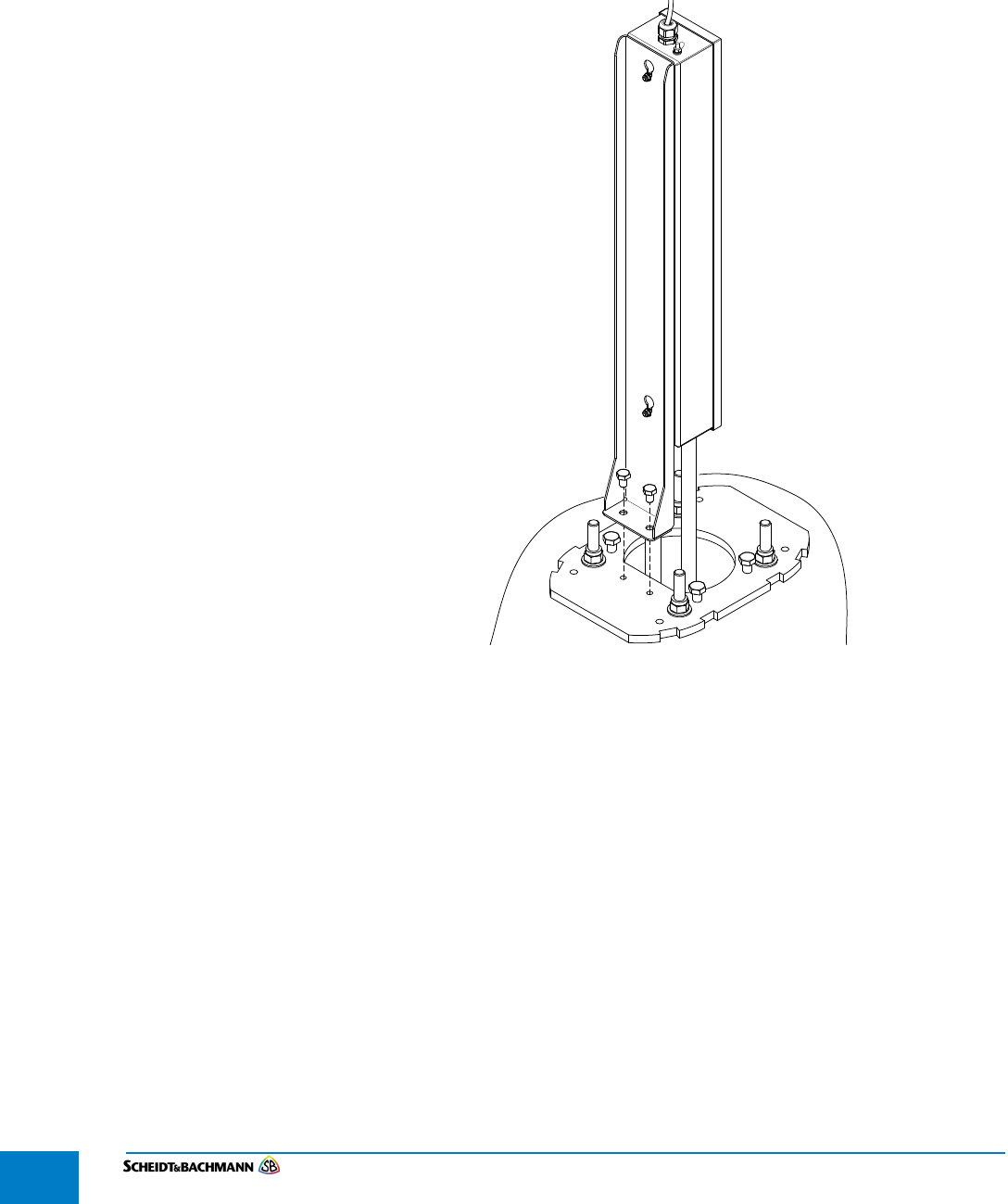
Chapter 4
Installation and Initialization
Edit: Stevens Art.#.: 86 —--, Version: 1.02 Datum:13.12.2017
4-42
4.8.2 Attaching the
Power Supply
Mount to the
Base Plate
The Power Supply Unit is comprised of two parts: the Power Supply Mount and
the Power Supply Junction Box.
The Power Supply Mount secures the power supply Junction Box to the base
plate inside the SV|51 housing ( Figure 4-18). Assemble the Power Supply
Mount on the level base plate using two hexagonal screws and tighten.
Figure 4-18 Power Supply Mount
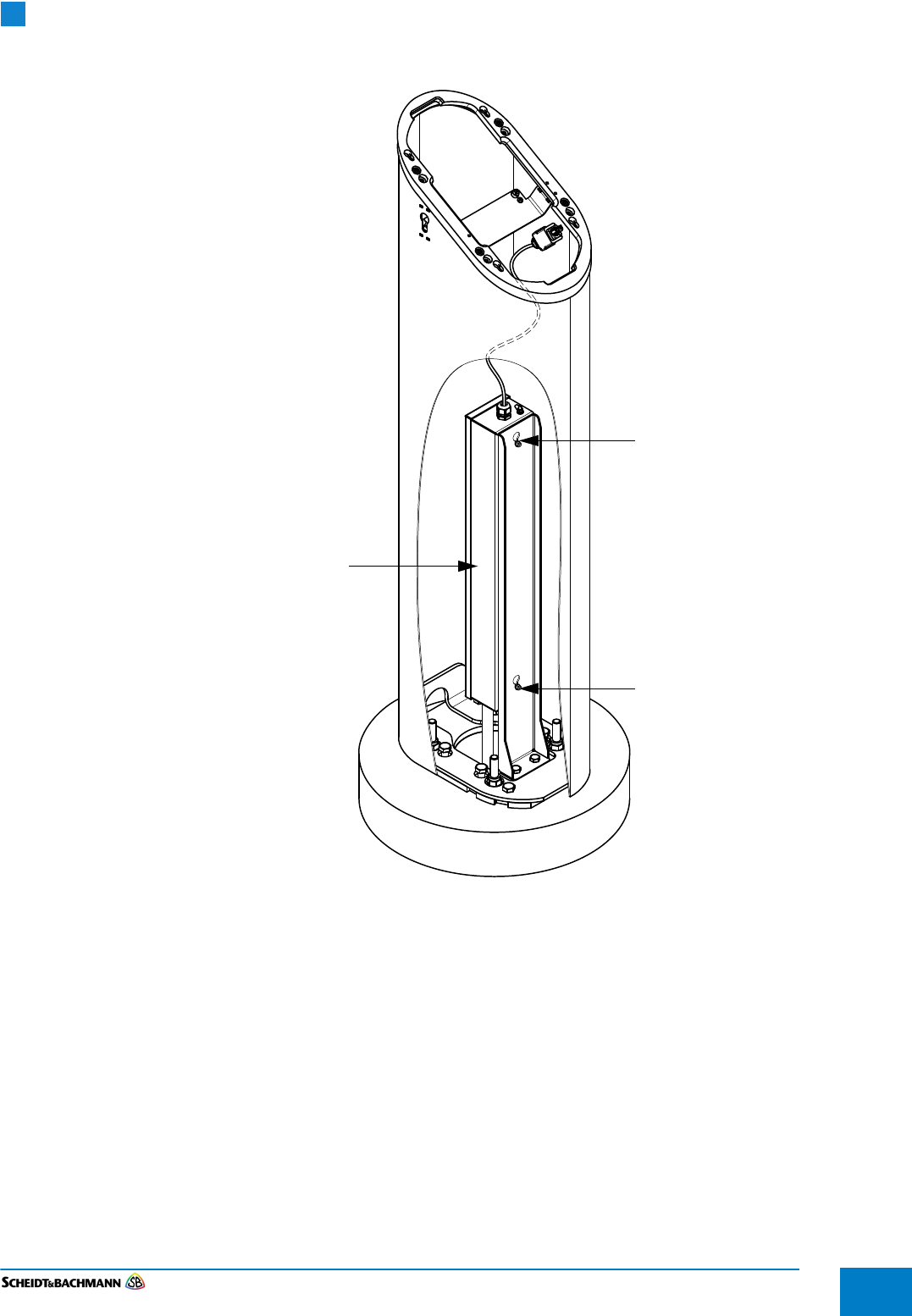
Chapter 4
Installation and Initialization
Edit: Stevens Art.#.: 86 ——, Version: 1.02 Datum:13.12.2017 4-43
Figure 4-19 Power Supply Junction Box Mounted
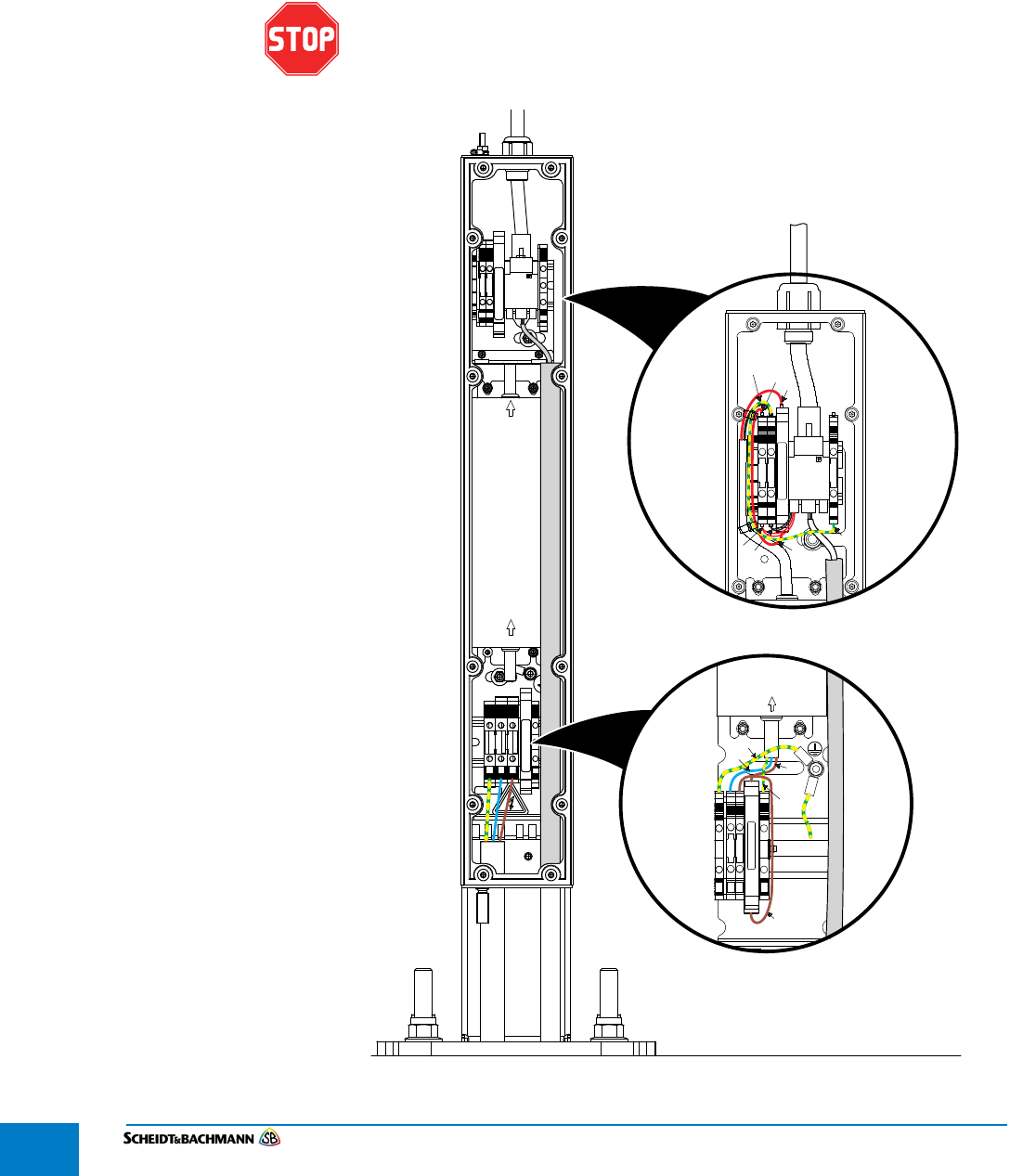
Chapter 4
Installation and Initialization
Edit: Stevens Art.#.: 86 —--, Version: 1.02 Datum:13.12.2017
4-44
4.8.3 Connecting
Cables
STEP 1: Switch off main circuit breaker.
STEP 2: Open the Power Supply Junction Box by removing the twelve screws and the
cover. Set aside the screws.
The cable entry into the device must be mechanically strain-relieved.
When the cable is pulled out, the connection of the protective earth
conductor must be established / existing until the end.
Figure 4-20 Cable Connections
GNL G
FOR WALLM.
G
21
GNL G
F1 — 6.3AT
CLG-60
F2 — 0.5AT
GNGE
SW RT
RT
RT
RT
SW+GNGE
ACINPUT
Supply
Power
DCOUTPUTACINPUT
F2 — 0.5AT
F1 — 6.3AT
GNGE
GNGE
BN
BL
BN
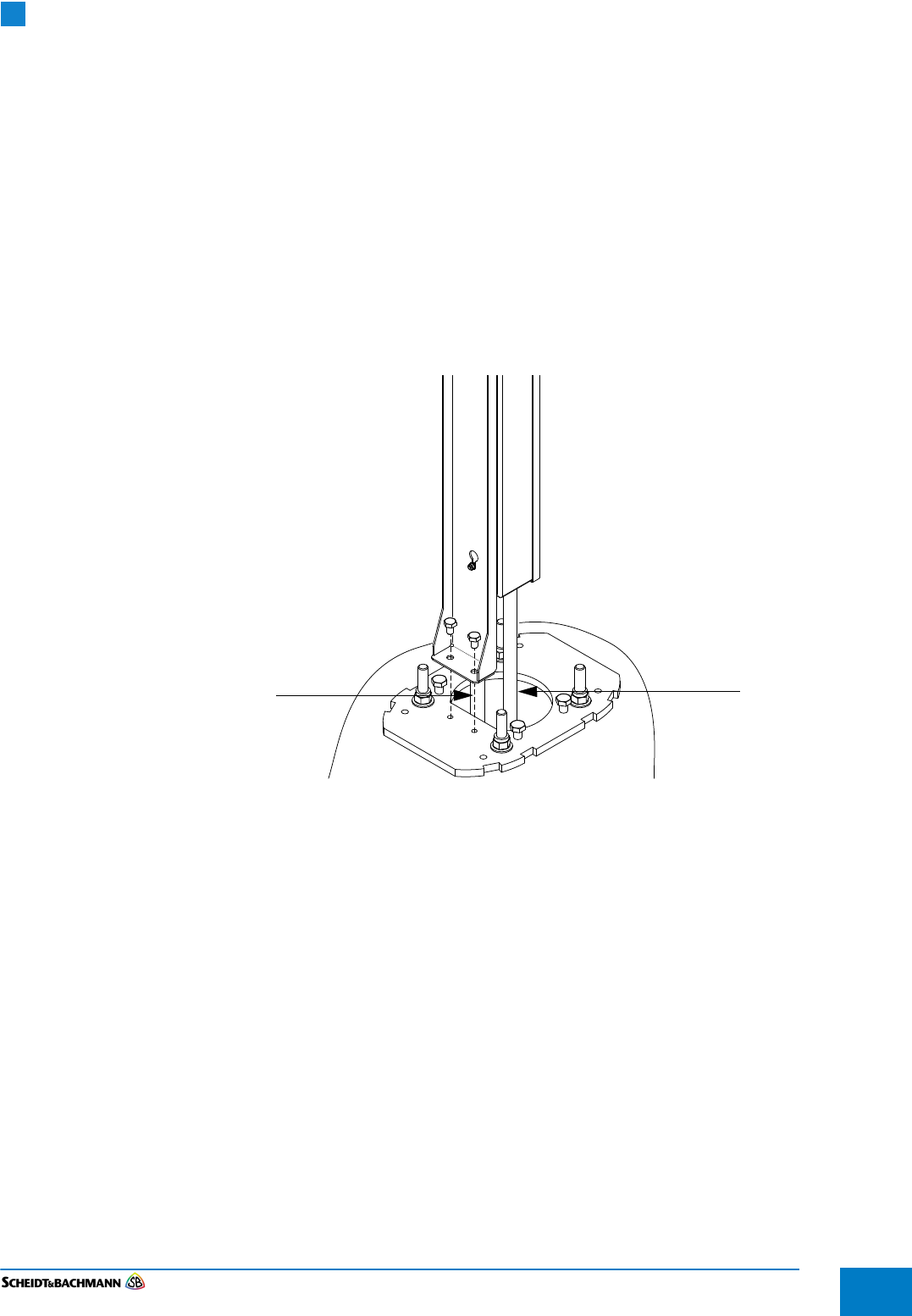
Chapter 4
Installation and Initialization
Edit: Stevens Art.#.: 86 ——, Version: 1.02 Datum:13.12.2017 4-45
STEP 3: Bottom Fed Conduit Entry: Ensure the power source and data cables are
passed through conduits from the bottom of the column up to the two entrance
points at the bottom of the Power Supply Junction Box.
Side Fed Conduit Entry: Ensure the power source and data cables are passed
through conduits from the back of the column up to the two entrance points at
the bottom of the Power Supply Junction Box.
STEP 4: The installer may choose which liquid sealants and fittings to use.
STEP 5: Connect the power source to its respective termination points at the bottom of
the Power Supply Junction Box as shown in Figure 4-20.
STEP 6: Run the data cable through the internal conduit and insert it at its termination
point near the top of the Power Supply Junction Box.
Figure 4-21 Data and Power Cables
The power supply inside the junction box combines the power source and data
into a single output (24V DC) with an RJ Industrial 10G Ethernet Cable Termina-
tion. Note that the power supply is delivered with this Ethernet Cable already
mounted. The other side of the pre-installed cable will be connected to the back
of the SV|51 main unit.
Replace the cover of the Power Supply Junction Box and secure it using the
twelve screws previously set aside.
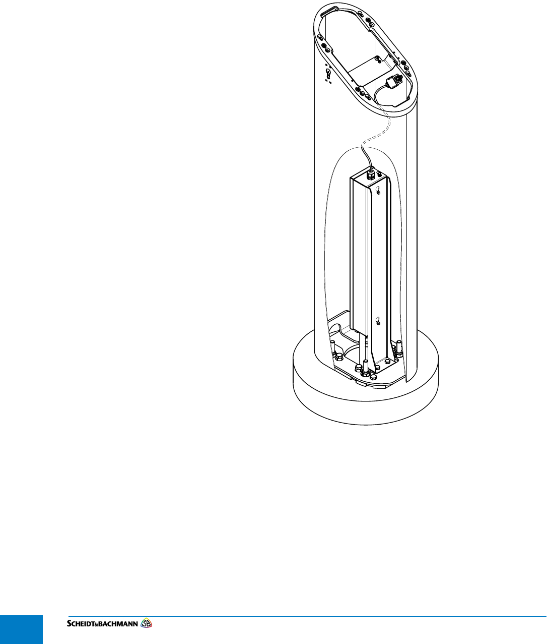
Chapter 4
Installation and Initialization
Edit: Stevens Art.#.: 86 —--, Version: 1.02 Datum:13.12.2017
4-46
4.8.4 Mounting the
Column to the
Base Plate
STEP 1: Place the column onto the base plate such that the lower side of the column
aligns with back side of the power supply unit.
Figure 4-22 Orientation of the Column with Respect to the Power Supply Unit
STEP 2: Ensure that the four outer screw openings on the base plate are aligned with the
screw openings on the welded mounting plate attached to the bottom of the
column.
Use the extended socket and ratchet to screw the four outer bolts that secure the
column on top of the base plate. For accurate leveling, the bolts need to be fas-
tened in a crosswise order.
STEP 3: Use a bubble level to ensure that the column is indeed level.
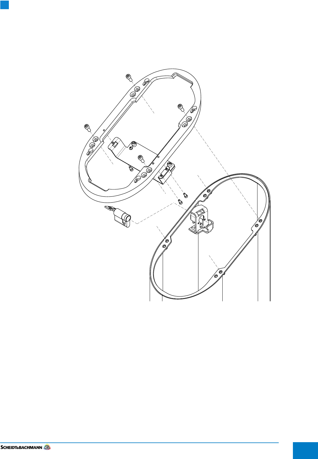
Chapter 4
Installation and Initialization
Edit: Stevens Art.#.: 86 ——, Version: 1.02 Datum:13.12.2017 4-47
4.8.5 Mounting the
Adapter Ring
The adapter ring has eight holes, four of which are used for the floor mount solu-
tion and the other four are included for a potential wall-mounted SV|51.
Figure 4-23 shows the orientation of the adapter ring on the column and the
four holes that are used for the floor mount solution.
Figure 4-23 Adapter Ring Orientation and Screws
STEP 1: Place the adapter ring on top of the column and slide the adapter ring from top
to bottom until it fits into place.
STEP 2: Ensure that the four screw openings of the adapter ring are aligned with the
corresponding four screw openings of the adapter ring mount.
STEP 3: Use four screws to secure the adapter ring to the column.
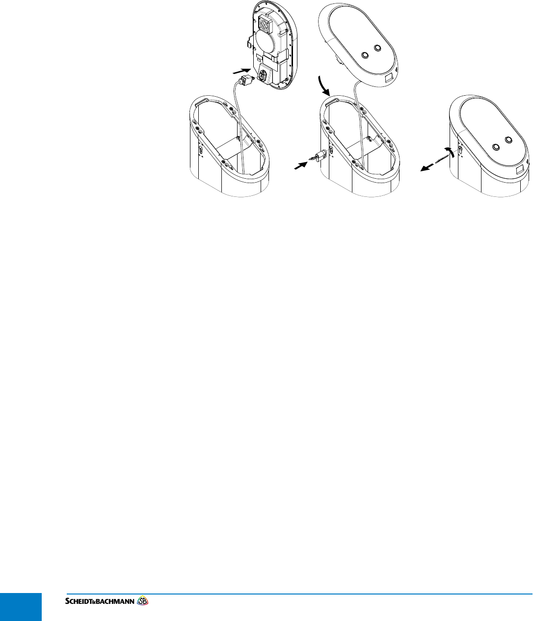
Chapter 4
Installation and Initialization
Edit: Stevens Art.#.: 86 —--, Version: 1.02 Datum:13.12.2017
4-48
4.8.6 Power and
Data
Connections
for the SV|51
The other side of the cable connected to the termination point of the Power Sup-
ply Junction Box connects to the back of the SV|51 to provide power and data
connection ( Figure 4-24).
STEP 1: Plug-in the RJ Industrial 10G Ethernet Cable Termination into the termination
point of the validator.
.
Figure 4-24 SV|51 Main Unit Assembly
NOTE: The four mushroom screws on the back of the SV|51 are pre-assembled
into the validator.
STEP 2: Hold the SV|51 on top of the adapter ring
STEP 3: Align the four Mushroom Screws on the back of the SV|51 with the appropriate
holes in the adapter ring.
STEP 4: Slide the validator down to secure it on top of the adapter ring.
STEP 1: Put the lock into the side of the column.
STEP 2: Lock the lock using the special key provided.

Chapter 4
Installation and Initialization
Edit: Stevens Art.#.: 86 ——, Version: 1.02 Datum:13.12.2017 4-49
4.9 Initialization
4.1.9 SV|51
Provisioning
Prerequisites
The following are the prerequisites for device provisioning:
New Device with the required firmware already installed
Personalized SAM card installed in the Device
Device is connected to the Production network/environment
Device Provisioning SD Card (SD Card A) which contains the PDS Device
Application installer packages
Location-specific labeled SD Card (SD Card B) containing Device
Configuration Data (Config.xml)
Factory SD Card

Chapter 4
Installation and Initialization
Edit: Stevens Art.#.: 86 —--, Version: 1.02 Datum:13.12.2017
4-50
4.1.9.1 Technical
Specifications
Mechanical dimensions
Width x Height x Depth
W = 200 mm (including Edge Connector)
H = 1127 mm
D = 320 mm
Weight ????
RoHS compliance
This product has been designed and
manufactured in compliance with Directive
2002/95/EC of the European Parliament and
the Council on restriction of the use of
certain hazardous substances in electrical
and electronic equipment (RoHS Directive).
Radio
Radio frequency: 2400 — 2483.5 MHz
Transmission power: 49 mW
Radio frequency: 5150-5775 MHz
Transmission power: 45 mW
Radio frequency: 13.56 MHz
Transmission power: 1.18 µW
IP rating
(ingress protection)
IP 54 (dust protected but not tight / splashing
water from all directions)
The SV|51 pole is not water tight, but the
power supply is (NEMA3)
IK rating
(impact protection)
IK 10 for option without buttons (20 Joule = 5
kg / 40 cm)
IK 09 for option with buttons (10 Joule = 5 kg
/ 20 cm)
Acceptance criteria: No break of front glass
allowed but minor optical impacts like
scratches are allowed.
Temperature Operating temperature: -30 to +50°C
Storage temperature: -40 to +70°C
Humidity 10% to 95% not condensing
Mechanical Stress
(Vibration test by ISO
16750-3)
Not required — (stationary device)
Electrical Safety EN 62368
EN 60950-22 (outdoor equipment)
EMC/EMI Emission: EN 61000-6-4 (class A)
Immunity: EN 50121-4 (class A)
Immunity against
overvoltage
The immunity to overvoltage is the task of
the baseboard were the Smart Card Reader
is plugged in.
(The Smart Card Reader must always be
supplied with a defined voltage)
Flammability UL 94 V1

Chapter 5
Module Removal
Edit: Stevens Art.#.: 86 ——, Version: 1.02 Datum:13.12.2017 5-51
Chapter 5 Module Removal
5.1 Module
Removal
This section discusses how to remove and replace components. Turn off power
at the main facility breaker before proceeding. Figure 5-25 shows the front and
back views of the main unit.
Figure 5-25 Front and Back Views of the main unit
These steps assume the installers followed the procedures outlined in
4.1.4 Side Conduit Entry or 4.1.5 Bottom Conduit Entry. If there is not
enough slack in the wires, as specified in the Installation Procedures,
alternative steps must be followed. See “Alternative Procedure” on
page 57.
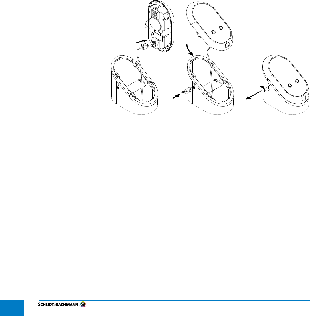
Chapter 5
Module Removal
Edit: Stevens Art.#.: 86 —--, Version: 1.02 Datum:13.12.2017
5-52
5.9.1 Main Unit The drawing in Figure 5-26 illustrates how to open the SV|51 and remove the
main unit.
STEP 1: Use the key to unlock the device.
STEP 2: Slide the main unit up and then pull up and away to disconnect it from the
stainless steel column.
STEP 3: Remove the cable.
STEP 4: Plug the cable into the new main unit.
STEP 5: Place the new main unit in the proper position on the stainless steel column and
then press down and slide to connect.
STEP 6: Use the key to lock the device.
Figure 5-26 SV|51 Main Unit Removal
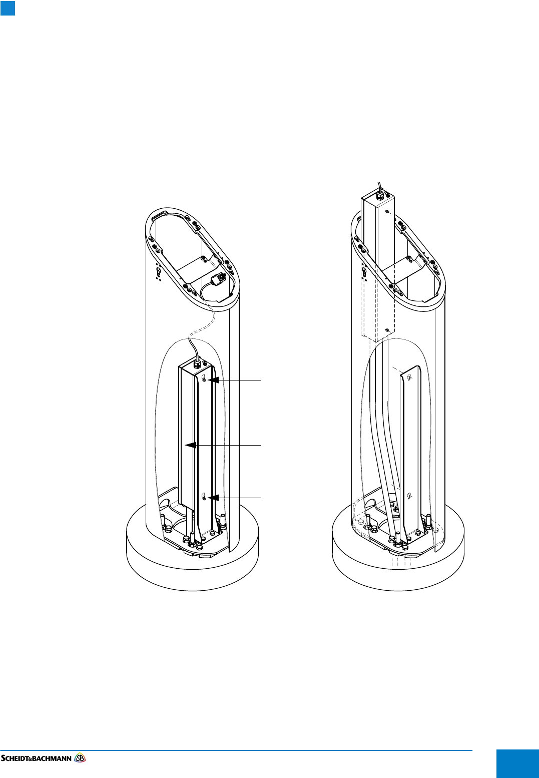
Chapter 5
Module Removal
Edit: Stevens Art.#.: 86 ——, Version: 1.02 Datum:13.12.2017 5-53
5.10 Accessing the
Power Supply
After removing the main unit as described in section 5.9.1, it is necessary to
access the power supply junction box. Use Figure 5-27 for reference.
STEP 1: Loosen the two screws attaching the power supply junction box to the power
supply mount. Leave them attached to the backside of the power supply unit.
STEP 2: Pull the power supply junction box upward and then outward, away from the
power supply mount.
STEP 3: Place the power supply junction box in a position convenient for removing the
back cover.
Figure 5-27 Accessing the Power Supply
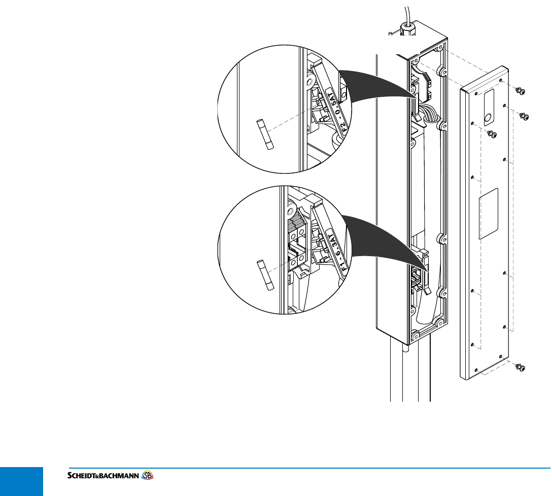
Chapter 5
Module Removal
Edit: Stevens Art.#.: 86 —--, Version: 1.02 Datum:13.12.2017
5-54
5.10.1 Fuse
Replacement
The drawing in Figure 5-28 shows how to replace the fuses in the main unit of
the SV|51.
STEP 1: Remove the main unit as described in section 5.9.1 and the power supply junc—
tion box as described in section 5.10.
STEP 2: Open the Power Supply Junction Box by removing the twelve screws and the
cover. Set aside the screws.
STEP 3: Lift the appropriate fuse cover and remove the blown fuse.
STEP 4: Insert a new fuse.
STEP 5: Replace the fuse cover.
STEP 6: Replace the cover and reinsert all twelve screws. Tighten appropriately.
STEP 7: Align the two screw openings at the Power Supply Mount with the two screw
heads of the power supply unit and slide it into position.
STEP 8: Tighten the two screws with a ratchet to secure the Power Supply Mount to its
holder.
Figure 5-28 Fuse Replacement
STEP 9: Re-install the main unit ( Figure 5-29).
Information
Technology Equipment
4NZ5
LISTED
USC
U
R
L
CLG-60
F2 — 0.5AT
F1 — 6.3AT
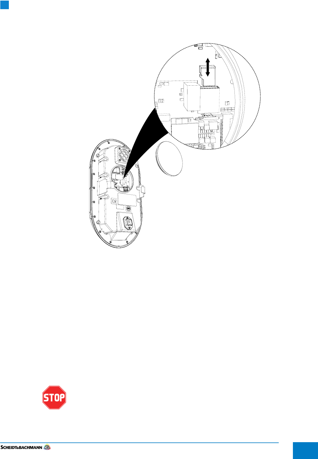
Chapter 5
Module Removal
Edit: Stevens Art.#.: 86 ——, Version: 1.02 Datum:13.12.2017 5-55
STEP 10: Lock the device.
Figure 5-29 MicroSD Card Removal
5.2 MicroSD
Card
Removal and
Replacement
The drawing in Figure 5-29 shows how to remove and replace the MicroSD
Card in the main unit.
STEP 1: Remove the main unit as described in section 5.9.1.
STEP 2: Remove the plate as shown in Figure 5-29.
STEP 3: Remove the MicroSD Card.
STEP 4: Replace the MicroSD Card.
STEP 5: Place the main unit on the stainless steel column and complete locking as
shown in Figure 5-30.
Only the shown MicroSD Card gets replaced in the field. S&B will ship the
device with the SD card on the CPU module inserted.
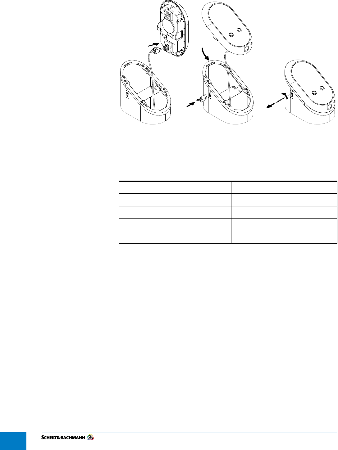
Chapter 5
Module Removal
Edit: Stevens Art.#.: 86 —--, Version: 1.02 Datum:13.12.2017
5-56
Figure 5-30 Main Unit Installation
5.3 Tools and
Con-
sumables
There are no consumables for this device. The only tool is a unique Lock used
to open and close the device.
Device or Component Name Part Number
SV|51 main unit 86 XXXX
Lock 86 XXXX
Key 86 XXXX
MicroSD Cards 51 03826 or local purchase
Table 5-5 Part Numbers

Chapter 5
Module Removal
Edit: Stevens Art.#.: 86 ——, Version: 1.02 Datum:13.12.2017 5-57
5.11 Alternative
Procedure
If there is not enough slack in the wires to follow the preferred procedure for
removing the power supply, follow these steps.
STEP 1: Turn off power at the main facility breaker before proceeding.
STEP 2: Remove the main unit as specified in 5.9.1
STEP 3: Remove the stainless steel column.
Remove all caulking around the base.
Use the extended socket and ratchet to unscrew the four outer bolts that
secure the column on top of the base plate. Put the four bolts in a safe place.
They will be used to re-install the stainless steel column.
Lift the stainless steel column up until there is enough clearance to avoid
damaging any components and set it aside.
STEP 4: At this point, it is possible to access the power supply.
Follow the steps in 5.10 and 5.10.1 to replace fuses and reattach the power
supply to the power supply mount.
STEP 5: Reinstall the stainless steel column as specified in 4.1.8 Mounting the Column
to the Base Plate.
STEP 6: Re-install the main unit ( Figure 5-30).
STEP 7: Lock the device.

Chapter 5
Module Removal
Edit: Stevens Art.#.: 86 —--, Version: 1.02 Datum:13.12.2017
5-58
THIS PAGE INTENTIONALLY BLANK.
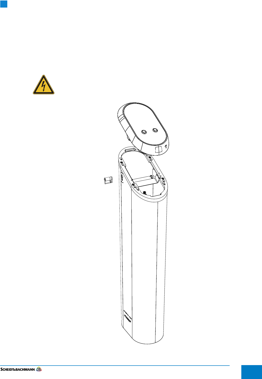
Chapter 6
Preventive Maintenance
Edit: Stevens Art.#.: 86 ——, Version: 1.02 Datum:13.12.2017 6-59
Chapter 6 Preventive Maintenance
6.1 General
Maintenance
and Cleaning
The following general preventive maintenance procedures are for the overall
maintenance and cleaning of the SV|51. This includes testing and validating the
equipment to ensure proper operation. During this Preventive Maintenance pro-
cess, notify the Network Control Administrator that alarms may be triggered.
Unless otherwise specified, the power must be turned “Off” prior to
performing maintenance procedures. Turn off power at the main facility
breaker before proceeding.
Figure 6-31 SV|51
Chapter 6
Preventive Maintenance
Edit: Stevens Art.#.: 86 —--, Version: 1.02 Datum:13.12.2017
6-60
6.12 Preventive
Maintenance
Schedule
Summary
Table 6—6 is a single source that summarizes all of the preventive maintenance
(PM) procedures mentioned in this chapter. Use this table to determine what
procedures that need to be accomplished, and when they should be scheduled.
When the recommended preventive maintenance intervals have both a
time period and a receipt usage maximum, then preventive maintenance
must take place when either the time or the usage maximum is reached.
These are maximum maintenance intervals, which may have to be
reduced, and they assume average usage in a moderate environment. If
certain machines are heavily used or exposed to atypical environmental
conditions, such as extreme temperature fluctuations or nearby construc-
tion work, then preventive maintenance must be undertaken more fre-
quently in order to reduce the amount and frequency of field
maintenance. Operation and maintenance histories should be consulted
and preventive maintenance procedures undertaken for those machines
and locations where experience shows more frequent preventive mainte-
nance will reduce field maintenance.
6.2 Materials and
Replacement
Parts
Table 6-7 provides a complete list of the materials and replacement parts
needed to perform preventive maintenance on the SV|51.
Table 6-6 Recommended PM Schedule/Frequency
FREQUENCY DESCRIPTION REFERENCE
Every Month Cleaning and Visual
Inspection of the Exterior
Section 6.2.2
Screen Preventive Maintenance Section 6.2.3
Lock Preventive Maintenance Section 6.2.4
Every Three Months Cleaning and Visual
Inspection of the Interior
Section 6.2.1
ITEM DESCRIPTION WHERE USED
Canned Air General Use
Alcohol Isopropyl, (70% min.) General Use
Lexan Cleaner Windex (or other mild
cleanser)
Customer Display
Heavy Duty Shop
Cloths
Lint-free, soft Miscellaneous Use
8633729 PRESTO
Card Tap Sticker
Sticker Card Tap Area
Table 6-7 Materials and Replacement Parts

Chapter 6
Preventive Maintenance
Edit: Stevens Art.#.: 86 ——, Version: 1.02 Datum:13.12.2017 6-61
6.13 Complete
Assembly
Follow these procedures for the preventive maintenance of the SV|51.
6.2.1 Cleaning and
Visual
Inspection of
Interior
Preventive maintenance cycle: Every 3 months
STEP 1: Remove any foreign materials from the inside of the SV|51 (see section 6.2).
STEP 2: Use canned air to remove small particles from the interior of the SV|51.
STEP 3: Clean the interior surface of the SV|51 Housing with alcohol.
STEP 4: Inspect the mounting of all the components.
STEP 5: Visually inspect the condition of all cables for wear and chafing.
6.2.2 Cleaning and
Visual
Inspection of
Exterior
Preventive maintenance cycle: Every Month
The exterior of the SV|51 should be kept clean.
STEP 1: Clean exterior of SV|51 with alcohol (see section 6.2).
STEP 2: Visually inspect the SV|51 exterior for damage.
6.2.3 Screen
Preventive maintenance cycle: Every Month
Perform the following maintenance and cleaning procedures for the Screen:
STEP 1: Clean exterior surface of the screen with a soft lint-free cloth and screen/window
cleaner (see section 6.2).
Do not use an acid-based cleaner.
STEP 2: Visually check the Display glass for any cracks or other damage.
6.2.4 Test for proper
adjustment of
the Lock Switch
The SV|51 Lock Switch must be checked for proper adjustment.
STEP 1: Insert the key into the lock and turn.
STEP 2: Turn the key to the closed position and remove.

Chapter 6
Preventive Maintenance
Edit: Stevens Art.#.: 86 —--, Version: 1.02 Datum:13.12.2017
6-62
THIS PAGE INTENTIONALLY BLANK.
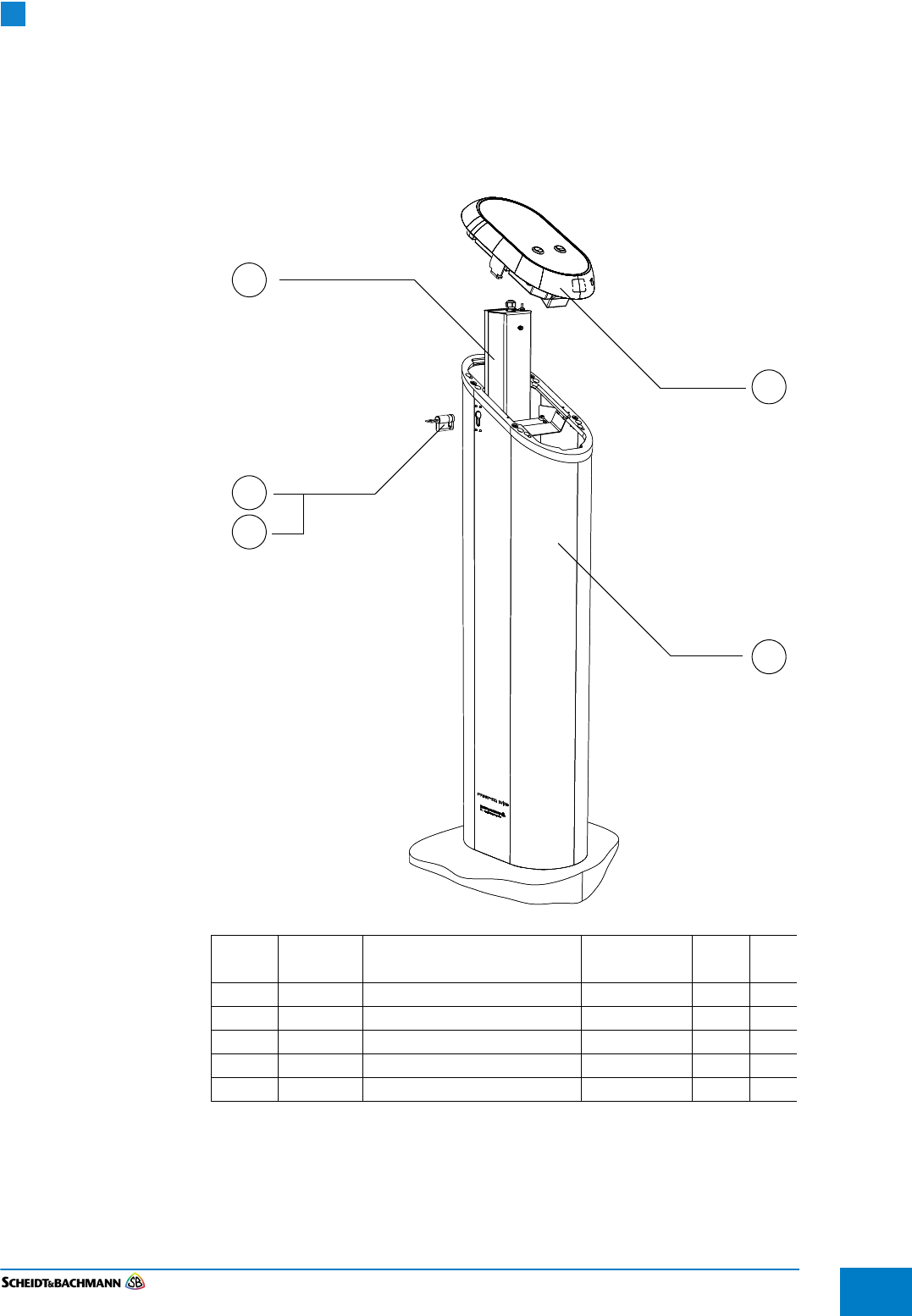
Chapter 7
IPC
Edit: Stevens Art.#.: 86 ——, Version: 1.02 Datum:13.12.2017 7-63
Chapter 7 IPC
7.1 IPC Pages IPC in this chapter give the customer an overview of the SV|51.
Figure
Item
S&B Part
Number
Part Description Available as
Spare Part
LLA Qty
10 86XXXX Functional Unit 1
20 0371705 Housing 0371292 Welded 1
30 86XXXX Key 1
40 86XXXX Lock 1
50 0371274 Junction Box for SV-50 1
10
20
40
50
30

Chapter 7
IPC
Edit: Stevens Art.#.: 86 —--, Version: 1.02 Datum:13.12.2017
7-64
THIS PAGE INTENTIONALLY BLANK.