
Модератор: vetal


 Ошибка 093-933- это программный глюк.
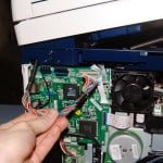
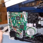
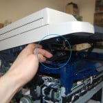
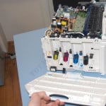
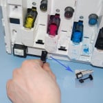
На датчике тонера в проявке много смеси тонера с девелопером. Надо освободить датчик от смеси. Наклоняем принтер назад на 90 градусов поднимая перед принтера (если больше 90 градусов сработает датчик открытия задней крышки) и немного трясем. Желательно снять переднюю крышку, чтобы видеть вращение шестерни подкачки тонера. Включаем принтер и ждем, когда включится подача ( если не включается подача, выключаем и включаем принтер несколько раз). как только включится подача опускаем принтер плавно. Принтер войдет в калибровку и будет подкачивать рывками тонер. После подкачки ошибка пропадает (если не пропадет- повторить выше написанные операции).
Смысл данного алгоритма- датчик определяет увеличение количества смеси при подкачке.
Причина возникновения ошибки не хватило тонера при калибровке.На 70 грамм девелопера требуется грамм 80 тонера ( по моим прикидкам). В режим калибровки входит только при отсутствии смеси на датчике.
Моя история ремонта :
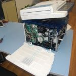
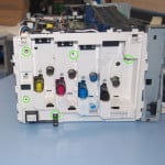
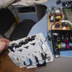
Разборка принтера при пробеге 5000 копий по причине еле заметного изображения. Девелопера осталось чайная ложка с горкой. Тонер не закачивался с нового картриджа. В бункере много отработки. Какой тонер использовался неизвестно.
Очищен картридж от девелопера и отработки.
В проявку насыпан девелопер Xerox Phaser 6180, 6280 (фл,70,кр) Silver ATM и собран принтер. Установлен картридж Кактус на 2300 копий.
При включении (несколько раз) принтер начал закачивать тонер пока не появилась ошибка 093-933. Весь тонер с Кактуса ( 50 грамм) принтер перекачал в проявку. Засыпал тонер Xerox Phaser 3040, 3010, WC3045 (кан. 30 г.) Absolute Black (Uninet) в пустой картридж Кактуса и заменил чип. Принтер не качал тонер и ошибка не пропала.
Далее работы по выше написанному алгоритму.
- За это сообщение автора Ильшат поблагодарили: 4
- GeneSIS, Magrom, omegaTM, Усатый Полосатый
-

Ильшат
- Осматривается
-
![]()
-
-
Xerox Phaser 6600 «Invalid Yellow» / «Неверный желтый»
kotya-potya в форуме Принтеры, МФУ, факсы, копиры формата A4
- 5
- 5692
3100

Пн ноя 18, 2019 8:24 pm
-
Xerox Phaser 6600 «Invalid Yellow» / «Неверный желтый»
-
-
Xerox WC 3119: «Замятие 1»
kokubenko в форуме Принтеры, МФУ, факсы, копиры формата A4
- 22
- 39497
kokubenko
Ср ноя 23, 2011 4:47 pm
-
Xerox WC 3119: «Замятие 1»
-
-
прошил xerox 3160b прошивкой FIX_b2580_1010079.fls не прошил
Володья в форуме Принтеры, МФУ, факсы, копиры формата A4
- 8
- 12976
Володья
Сб апр 30, 2011 8:05 am
-
прошил xerox 3160b прошивкой FIX_b2580_1010079.fls не прошил
-
-
Xerox WC3220 — Ложное замятие бумаги, Замятие 0
Romeo в форуме Принтеры, МФУ, факсы, копиры формата A4
- 25
- 11257
Romeo
Пн окт 12, 2020 7:13 pm
-
Xerox WC3220 — Ложное замятие бумаги, Замятие 0
-
-
Xerox 3315 «слетела» FIX прошивка
tekknik в форуме Принтеры, МФУ, факсы, копиры формата A4
- 7
- 7247
tekknik
Пн июн 10, 2019 4:22 am
-
Xerox 3315 «слетела» FIX прошивка
Вернуться в Принтеры, МФУ, факсы, копиры формата A4
Кто сейчас на форуме
Сейчас этот форум просматривают: нет зарегистрированных пользователей и гости: 82
You are here: Home / error code / Xerox WorkCentre 6015 error and solving error codes
– Compatible Printer model: Xerox WorkCentre 6015
– Xerox WorkCentre 6015 Error Codes with quick guides:
- Code:
- Description: System Restart An internal IP Board error occurred.
- Causes: • IP Board, PL7.1.9
- Troubleshooting Guides: 1 Check the connectors on the IP Board. Are the connections secure? Go to step 3. Securely reconnect the connectors, then go to step 2. 2 Does the error persist? Go to step 3. Complete. 3 Replace the IP Board. Does the error persist? Complete.
- Code: 005-121
- Description: ADF Jam
- Causes: • IP Board, PL7.1.9 • ADF Assembly, PL8.1.1 • ADF Cover, PL8.1.3 • ADF Separator Pad, PL8.
- Troubleshooting Guides: 1 Is the ADF closed against the document glass completely? Go to step 2. Close the ADF completely and go to step 2. 2 Does the error persist? Go to step 3. Complete. 3 Reseat P/J1, P/J6, and P/J16 on the IP Board. Does the error persist? Go to step 4. Complete. 4 Does the ADF feed the document? Go to step 5. Go to step 7. 5 Open the ADF Cover and check the document path. Is there foreign substance on the document path? Remove the foreign substance. Go to step 6. Go to step 7. 6 Does the error persist? Go to step 7. Complete. 7 Clean the ADF feed rollers. Do the feed rollers rotate smoothly? Go to step 8. Replace the ADF. 8 Replace the IP Board. Does the error persist? Replace the ADF Cover and ADF Separator Pad.
- Code: 005-301
- Description: ADF Cover Open
- Causes: • IP Board, PL7.1.9 • ADF Assembly, PL8.1.1
- Troubleshooting Guides: 1 Is the ADF Cover completely closed? Go to step 3. Close the ADF cover and go to step 2. 2 Does the error persist? Go to step 3. Complete. 3 Is the ADF Cover damaged? Replace the ADF Cover. Go to step 4. Go to step 5. 4 Does the error persist? Go to step 5. Complete. 5 Reseat P/J1, P/J6, and P/J16 on the IP Board. Does the error persist? Go to step 6. Complete. 6 Replace the ADF. Does the error persist? Replace the IP Board. Complete.
- Code: 007-340
- Description: Main Motor Failure Fuser Error
- Causes: • Main Drive Assembly, PL6.1.2 • Harness Assembly Main MOT, PL 6.1.7 • MCU Board, PL7.2.2
- Troubleshooting Guides: 1 Check these connections • MCU Board P/J16 • Main Drive Assembly P/J160 Are the connectors secure? Go to step 3. Secure the connectors and then go to step 2. 2 Does the error persist? Go to step 3. Complete. 3 Check the Main Drive Assembly for rotation. For the 6000B, see gDigital Output Test Proceduresh on page A-16, or for the 6015 MFPs, see gWorkCentre 6015 MFP Motor Test Proceduresh. Does the Main Drive Assembly function normally? Replace the MCU Board. Go to step 4. 4 Check the Main Drive Assembly for proper installation. Is the Main Drive Assembly installed correctly? Go to step 6. Reseat the Main Drive Assembly, and go to step 5. 5 Does the error persist? Go to step 6. Complete. 6 Checking the Harness Assembly Main MOT for continuity. Disconnect P/J16 from the MCU Board, and P/J160 from the Main Drive Assembly. Is each cable of P/J16 <=> P/J160 continuous? Go to step 7. Repair the harness. 7 Disconnect the P/J16 on the MCU Board. Are the voltages across ground to P/J6-2pin/P/J6-4 pin on the MCU Board approximately +24 VDC when the Interlock Switch is pushed? Replace the Main Drive Assembly. Replace the MCU Board.
- Code: 009-360 … 009-363
- Description: X CRU Life Over The indicated Toner Cartridge has reached end of life. • 009-360 to 009-363: Replace Toner Cartridge Now
- Causes: • Harn assy dckr, PL4.1.2 • MCU Board, PL7.2.2
- Troubleshooting Guides: 1 Reseat the appropriate Toner Cartridge. Does the error persist? Go to step 2. Complete. 2 Does the error persist when the power is turned off and on? Go to step 3. Complete. 3 Check P/J13 on the MCU Board. Is the connection secure? Go to step 5. Reconnect P/J13, then go to step 4. 4 Does the error persist? Go to step 5. Complete. 5 Disconnect P/J13 on the MCU Board, and inspect the harness. Is the harness damaged? Repair the harness, then go to step 6. Go to step 7. 6 Does the error persist? Go to step 7. Complete. 7 Replace the Toner Cartridge (C, M, Y, or K). Does the error persist? Replace the MCU Board, then go to step 4. Contact your designated field support for assistance.
- Code: 010-397
- Description: Fuser Error
- Causes: • Fuser, PL5.1.1 • MCU Board, PL7.2.2
- Troubleshooting Guides: 1 Reseat the Fuser and cycle system power. Does the error persist? Go to step 2. Complete. 2 Check these connections • MCU Board P/J26 and P/J18. • LVPS P/J201. Are the connectors secure? Go to step 3. Secure the connectors. 3 Check the Fuser harness. 1. Remove the Fuser. 2. Disconnect P/J26 and P/J18 from the MCU Board and P/J201 from the LVPS. Is the harness damaged? Repair the harness. Go to step 4. 4 Replace the Fuser. Does the error persist? Replace the MCU Board. Complete.
- Code: 016-315, 016-317
- Description: IP Memory Check Fail
- Causes: • IP Board, PL7.1.9 • MCU Board, PL7.2.2 • LED Driver Board, PL7.1.5
- Troubleshooting Guides: 1 Reseat all connectors on the IP Board and the MCU Board. Does the error persist? Go to step 2. Complete. 2 Replace the LED Driver Board. Does the error persist? Go to step 3. Complete. 3 Replace the IP Board. Does the error persist? Replace the MCU Board. Complete.
- Code: 016-323
- Description: Fax Checksum Error
- Causes: • IP Board, PL7.1.9 • MCU Board, PL7.2.2
- Troubleshooting Guides: 1 Reseat all connectors on the IP Board and the MCU Board. Does the error persist? Go to step 2. Complete. 2 Replace the IP Board. Does the error persist when the power is turned on? Replace the MCU Board. Complete.
- Code: 016-372
- Description: DRAM Memory Allocation Error
- Causes: • IP Board, PL7.1.9 • MCU Board, PL7.2.2
- Troubleshooting Guides: 1 Reseat all connectors on the IP Board and the MCU Board. Does the error persist? Go to step 2. Complete. 2 Replace the IP Board. Does the error persist when the power is turned on? Replace the MCU Board. Complete.
- Code: 016-500, 016-501, 016-502
- Description: Firmware Errors. The firmware download to the printer failed. • 016-500: Erase Flash Error • 016-501: Write Flash Error • 016-502: Verify Flash Error
- Causes: • IP Board, PL7.1.9 • MCU Board, PL7.2.2 • LED Driver Board, PL7.1.5
- Troubleshooting Guides: 1 Reseat all connectors on the IP Board and the MCU Board. Does the error persist? Go to step 2. Complete. 2 Replace the LED Driver Board. Does the error persist when the power is turned on? Go to step 3. Complete. 3 Replace the IP Board. Does the error persist when the power is turned on? Replace the MCU Board. Complete.
- Code: 016-503 … 016-507
- Description: E-mail Error An e-mail error is detected. • 016-503: SMTP Error • 016-504: POP Error • 016-506: SMTP Login Error • 016-507: SMTP Error
- Causes: • IP Board, PL7.1.9 • MCU Board, PL7.2.2
- Troubleshooting Guides: 1 Reseat all connectors on the IP Board and the MCU Board. Does the error persist? Go to step 2. Complete. 2 Replace the IP Board. Does the error persist when the power is turned on? Replace the MCU Board. Complete.
- Code: 016-718
- Description: Memory Overflow The print job size exceeded memory.
- Causes: • IP Board, PL7.1.9/PL7.1.16 • MCU Board, PL7.2.2
- Troubleshooting Guides: 1 Check the memory. Print the Configuration Page to determine the amount of memory installed. Is the print job too large? Divide the print job to fit installed memory. Go to step 2. 2 Reseat all connections on the IP Board. Does the error persist? Go to step 3. Complete. 3 Replace the IP Board. Does the error persist? Go to step 4. Complete. 4 Replace the MCU Board. Complete.

Solve Xerox WorkCentre 6015 Error codes
- Code: 016-719
- Description: Decode Error
- Causes: • IP Board, PL7.1.9 • MCU Board, PL7.2.2
- Troubleshooting Guides: 1 Reseat all connectors on the IP Board and the MCU Board. Does the error persist? Go to step 2. Complete. 2 Replace the IP Board. Does the error persist when the power is turned on? Replace the MCU Board. Complete.
- Code: 016-737 … 016-745
- Description: Download Errors The system firmware file is corrupt or communications to the printer failed. • 016-737: Download ID Error • 016-741: Download Range Error • 016-742: Download Header Error • 016-743: Download Checksum Error • 016-744: Download Format Error • 016-745: Download Protect Error
- Causes: • IP Board, PL7.1.9/7.1.16 • MCU Board, PL7.2.2
- Troubleshooting Guides: 1 Reseat all connectors on the IP Board and the MCU Board. Does the error persist? Go to step 2. Complete. 2 Replace the IP Board. Does the error persist? Replace the MCU Board, and then go to step 3. Complete. 3 Does the error persist? Contact your designated field support for assistance. Complete.
- Code: 016-749
- Description: PJL Request Error
- Causes: • IP Board, PL7.1.9/7.1.16 • MCU Board, PL7.2.2
- Troubleshooting Guides: 1 Reseat all connectors on the IP Board and the MCU Board. Does the error persist? Go to step 2. Complete. 2 Replace the IP Board. Does the error persist? Replace the MCU Board. Complete.
- Code: 016-764, 016-766, 016-767
- Description: E-mail Errors An e-mail error is detected. • 016-764: Connect Error • 016-766: SMTP Error • 016-767: E-mail Address Error
- Causes: • IP Board, PL7.1.9 • MCU Board, PL7.2.2
- Troubleshooting Guides: 1 Reseat all connectors on the IP Board and the MCU Board. Does the error persist? Go to step 2. Complete. 2 Replace the IP Board. Does the error persist when the power is turned on? Replace the MCU Board. Complete.
- Code: 016-791, 016-795, 016-797
- Description: USB Memory Removal Error USB memory is removed while memory reading job is being executed. • 016-791: USB Memory Removal Error • 016-795: File Format Error • 016-797: File Read Error
- Causes: • IP Board, PL7.1.9/PL7.1.16 • MCU Board, PL7.2.2
- Troubleshooting Guides: 1 Reseat all connections on the IP Board and MCU Board. Does the error persist? Go to step 2. Complete. 2 Replace the IP Board. Does the error persist? Go to step 3. Complete. 3 Replace the MCU Board. Complete.
- Code: 016-799
- Description: Invalid Job Invalid print job settings.
- Causes: • IP Board, PL7.1.9/PL7.1.16 • MCU Board, PL7.2.2
- Troubleshooting Guides: 1 Reseat all connections on the IP Board and MCU Board. Does the error persist? Go to step 2. Complete. 2 Replace the IP Board. Does the error persist? Go to step 3. Complete. 3 Replace the MCU Board. Complete.
- Code: 016-920
- Description: Wireless Error
- Causes: • IP Board, PL7.1.9B • MCU Board, PL7.2.2
- Troubleshooting Guides: 1 Reseat all connections on the IP Board and MCU Board. Does the error persist? Go to step 2. Complete. 2 Replace the IP Board. Does the error persist? Go to step 3. Complete. 3 Replace the MCU Board. Complete.
- Code: 016-930, 016-931
- Description: USB Host Error. An unsupported USB memory device was attached to the USB port. • 016-930: USB Host Full • 016-931: USB Host Error
- Causes:
- Troubleshooting Guides: Unplug the unsupported device.
- Code: 016-981
- Description: Collate Full The print job is too large.
- Causes: • IP Board, PL7.1.9 • MCU Board, PL7.2.2
- Troubleshooting Guides: 1 Reseat all connectors on the IP Board and the MCU Board. Does the error persist? Go to step 2. Complete. 2 Replace the IP Board. Does the error persist when the power is turned on? Replace the MCU Board. Complete.
- Code: 016-985, 017-970, 017-988
- Description: Mail Size Limits Error, PCScan Time Out, Memory Full. • 016-985: Mail Size Limits Error • 017-970: PCScan Time Out • 017-988: Memory Full
- Causes: • IP Board, PL7.1.9 • MCU Board, PL7.2.2
- Troubleshooting Guides: 1 Reseat all connectors on the IP Board and the MCU Board. Does the error persist? Go to step 2. Complete. 2 Replace the IP Board. Does the error persist when the power is turned on? Replace the MCU Board. Complete.
- Code: 017-980, 017-981
- Description: Report File Open/Close Error • 017-980: Report File Open/Close Error • 017-981: Report File Error
- Causes: • IP Board, PL7.1.9 • MCU Board, PL7.2.2
- Troubleshooting Guides: 1 Reseat all connectors on the IP Board and the MCU Board. Does the error persist? Go to step 2. Complete. 2 Replace the IP Board. Does the error persist when the power is turned on? Replace the MCU Board. Complete.
- Code: 017-990
- Description: Scanner Calibration Failure Calibration of the Scanner failed.
- Causes: • IP Board, PL7.1.9 • MCU Board, PL7.2.2 • Scanner, PL8.1.1
- Troubleshooting Guides: 1 Reseat all connectors on the IP Board and the MCU Board. Does the error persist? Go to step 2. Complete. 2 Replace the IP Board. Does the error persist? Replace the MCU Board, then go to step 3. Complete. 3 Does the error persist? Replace the Scanner. Complete.
- Code: 018-338
- Description: Wireless Error A wireless error is detected.
- Causes: • IP Board, PL7.1.9B • Wireless Harness, PL1.1.31 • Wireless Board Bracket, PL1.1.30
- Troubleshooting Guides: 1 Check the connections between the IP Board and the Wireless Board. Are P/J6601 and P/J6501 properly connected? Go to step 2. Reconnect the connections, then go to step 2. 2 Does the error persist? Go to step 3. Complete. 3 Disconnect P/J6601 on the IP Board, and P/J6501 on the Wireless Board. Is each cable of the Wireless Harness continuous? Go to step 4. Replace the Wireless Harness. 4 Replace the Wi-Fi Board. Does the error persist when the power is turned on? Replace the IP Board. Complete.
- Code: 024-340
- Description: A firmware error has occurred.
- Causes: • MCU Board, PL7.2.2
- Troubleshooting Guides: 1 Replace the MCU Board. Does the error persist? Perform the Electrical Noise check. Complete.
- Code: 024-360
- Description: Download Error MCU firmware download failure.
- Causes: • MCU Board, PL7.2.2
- Troubleshooting Guides: 1 Reseat all connections on the IP Board and MCU Board. Does the error persist? Go to step 2. Complete. 2 Replace the MCU Board. Does the error persist? Perform the Electrical Noise check. Contact your designated field support for assistance.
- Code: 024-371
- Description: MCU Comm Error Communication has failed between the MCU and IP Boards.
- Causes: • IP Board, PL7.1.9/7.1.16 • MCU Board, PL7.2.2
- Troubleshooting Guides: 1 Reseat the connectors on the IP and MCU Boards then cycle system power. Does the error persist? Go to step 2. Complete. 2 Check the Image Processor Harness continuity. Disconnect the IP Board P/J8 and the MCU Board P/J22. Is the harness damaged? Replace the harness. Go to step 3. 3 Replace the IP Board. Does the error persist? Replace the MCU Board. Complete.
- Code: 024-958
- Description: Paper Size Mismatch The size of paper in the Main Paper Tray, or Bypass Tray, does not match the specified print size.
- Causes: • Registration Sensor, PL2.3.5 • Harness Assembly RKN SNS, PL2.2.25 • MCU Board, PL7.2.2
- Troubleshooting Guides: 1 Check connectors P/J12 and P/J120 between the MCU Board and the Registration Sensor. Are the connections secure? Go to step 2. Securely reconnect the connectors, then go to step 2. 2 Does the error persist? Go to step 3. Complete. 3 Disconnect the MCU Board P/J12 and the Registration Sensor P/J120. Check the Harness Assembly RKN SNS for continuity. Is the harness damaged? Repair the harness. Go to step 4. 4 Disconnect the MCU Board P/J12. Is the voltage across ground and J12-1 +3.3 VDC? Replace the Registration Sensor. Replace the MCU Board.
- Code: 024-963
- Description: No Suitable Paper The Main Paper Tray, or Bypass Tray, has run out of paper, or the size (or type) of paper does not match the specified print size (or type).
- Causes: • Registration Sensor, PL2.3.5 • Harness Assembly RKN SNS, PL2.2.25 • MCU Board, PL7.2.2
- Troubleshooting Guides: 1 Check P/J12 on the MCU Board and P/J120 on the Registration Sensor. Are the connections secure? Go to step 2. Securely reconnect the connectors, then go to step 2. 2 Does the error persist? Go to step 3. Complete. 3 Disconnect the MCU Board P/J12 and the Registration Sensor P/J120. Check the Harness Assembly RKN SNS for continuity. Is the harness damaged? Repair the harness. Go to step 4. 4 Replace the IP Board. Does the error persist? Go to step 5. Complete. 5 Disconnect the MCU Board P/J12. Is the voltage across ground and J12-1 +3.3VDC? Replace the Registration Sensor. Replace the MCU Board.
- Code: 026-720, 026-721
- Description: USB Memory Full/USB Memory Write Error. A memory full error or USB memory write error occurred during a scan job. • 026-720: USB Memory Full • 026-721: USB Memory Write Error
- Causes: • IP Board, PL7.1.9 • MCU Board, PL7.2.2
- Troubleshooting Guides: 1 Check the connectors on the IP Board. Are the connections secure? Go to step 3. Securely reconnect the connectors, then go to step 2. 2 Does the error persist? Go to step 3. Complete. 3 Replace the IP Board. Does the error persist? Go to step 4. Complete. 4 Replace the MCU Board. Complete.
- Code: 026-722, 026-723
- Description: USB Memory Write Protect Error / File Path Limit Error A communication error occurred during a scan job. • 026-722: USB Memory Write Error • 026-723: File Path Limit Error
- Causes: • IP Board, PL7.1.9 • MCU Board, PL7.2.2
- Troubleshooting Guides: 1 Check the connectors on the IP Board. Are the connections secure? Go to step 3. Securely reconnect the connectors, then go to step 2. 2 Does the error persist? Go to step 3. Complete. 3 Replace the IP Board. Does the error persist? Go to step 4. Complete. 4 Replace the MCU Board. Complete.
- Code: 026-750, 026-751, 026-752
- Description: Scan Communication Fail A communication error occurred during a scan job.
- Causes: • IP Board, PL7.1.9 • MCU Board, PL7.2.2
- Troubleshooting Guides: 1 Check the connectors on the IP Board. Are the connections secure? Go to step 3. Securely reconnect the connectors, then go to step 2. 2 Does the error persist? Go to step 3. Complete. 3 Replace the IP Board. Does the error persist? Go to step 4. Complete. 4 Replace the MCU Board. Complete.
- Code: 027-446
- Description: IPv6 Duplicate Duplicate IPv6 addresses detected upon startup.
- Causes: • IP Board, PL7.1.9 • MCU Board, PL7.2.2
- Troubleshooting Guides: 1 Reseat the connectors on the IP and MCU Boards then cycle system power. Does the error persist? Go to step 2. Complete. 2 Replace the IP Board. Does the error persist when the power is turned off and on? Replace the MCU Board. Complete.
- Code: 027-452
- Description: IPv4 Duplicate Duplicate IPv4 addresses detected upon startup.
- Causes:
- Troubleshooting Guides: 1 At the printer’s Control Panel, press the Menu key. Using the Up Arrow, Down Arrow, and OK keys, navigate to Admin Menu > Network Settings >TCP/IP > IPv4 > Get Address. Is Get Address set to Panel? The printer is trying to use an address that is being used by another device on the network. Change the printer’s address. Another device is trying to use the printer’s address. Find the other device and resolve the problem by changing the other device’s address.
- Code: 031-521 … 031-558
- Description: SMB Error • 031-521: SMB Login Error • 031-526: SMB Name Resolve Error • 031-530: SMB Path Error • 031-533: SMB File Make Error • 031-534: SMB Folder Make Error • 031-535: SMB Delete File Error • 031-536: SMB Delete Folder Error • 031-537: SMB Disk Full Error • 031-556: SMB Write Error • 031-557: SMB File Duplication Error • 031-558: SMB Connect Error
- Causes: • IP Board, PL7.1.9 • MCU Board, PL7.2.2
- Troubleshooting Guides: 1 Reseat the connectors on the IP and MCU Boards then cycle system power. Does the error persist? Go to step 2. Complete. 2 Replace the IP Board. Does the error persist? Replace the MCU Board. Complete.
- Code: 031-529, 031-555
- Description: SMB Connection Error A SMB connection error occurred. • 031-529: SMB Login Failed • 031-555: SMB Connect Error
- Causes: • IP Board, PL7.1.9 • MCU Board, PL7.2.2
- Troubleshooting Guides: 1 Reseat the connectors on the IP and MCU Boards then cycle system power. Does the error persist? Go to step 2. Complete. 2 Replace the IP Board. Does the error persist? Replace the MCU Board. Complete.
- Code: 033-503, 033-513, 033-788
- Description: Memory Error • 033-503: Out of Memory • 033-513: Memory Full • 033-788: Communication Error
- Causes: • IP Board, PL7.1.9 • MCU Board, PL7.2.2
- Troubleshooting Guides: 1 Reseat the connectors on the IP and MCU Boards then cycle system power. Does the error persist? Go to step 2. Complete. 2 Replace the IP Board. Does the error persist? Replace the MCU Board. Complete.
- Code: 041-340
- Description: NVRAM Error
- Causes: • MCU Board, PL7.2.2
- Troubleshooting Guides: 1 Perform the Electrical Noise test. Does the error persist? Go to step 2. Complete. 2 Replace the MCU Board. Does the error persist when the power is turned on? Contact your designated field support for assistance. Complete.
- Code: 042-325
- Description: Motor Error The Main Drive Assembly has failed.
- Causes: • Main Drive Assembly, PL6.1.2 • Main Motor Harness, PL6.1.7 • MCU Board, PL7.2.2
- Troubleshooting Guides: 1 Check the connections between the MCU Board P/J16 and the Main Drive Assembly P/J160. Are the connections secure? Go to step 3. Reconnect the connectors, then go to step 2. 2 Does the error persist? Go to step 3. Complete. 3 Is the Main Drive Assembly installed correctly? Go to step 4. Reseat the Main Drive Assembly, then go to step 5. 4 Does the error persist when the power is turned off and on? Go to step 5. Complete. 5 Check the Main Drive harness continuity. Disconnect P/J16 from the MCU Board and P/J160 from the Main Drive Assembly to check continuity. Is the harness damaged? Repair the harness. Go to step 6. 6 Check the power to the Main Drive Assembly. Disconnect connector P/J16 on the MCU Board. Are the voltages across ground at P/J16-2 and P/J16-4 approximately +24 VDC when the Interlock Switch is closed? Replace the Main Drive Assembly. Replace the MCU Board.
- Code: 042-358
- Description: Fan Motor Failure Fan motor failure.
- Causes: • LVPS, PL 7.2.1 • Fan, PL 7.1.2 • MCU Board, PL7.2.2
- Troubleshooting Guides: 1 Check the connections between the FAN and LVPS. Is P/J205 on the LVPS securely connected? Go to step 2. Reconnect connector P/J205, then go to step 2. 2 Does the error persist? Go to step 3. Complete. 3 Disconnect P/J205 on the LVPS. Is the voltage across ground at P/J205-1 approximately +24 VDC when the Interlock Switch is pushed? Go to step 4. Replace the LVPS. 4 For the 6010N: Test the Fan (see “Using Phaser 6010N and WorkCentre 6015 MFP Service Diagnostics”). For the 6000: Test the Fan with the CE Diags Tool (see page A-16). Does the Fan function normally? Complete. Replace the MCU Board.
- Code: 042-372
- Description: Deve Mode Change Failure
- Causes: • Feed Solenoid, PL6.1.10 • Switching Sensor • Harness Assembly RKN SNS PL2.2.25/26 • Developer Drive Assembly, PL6.1.6 • MCU Board, PL7.2.2
- Troubleshooting Guides: 1 Check the P/J10 connector on the MCU Board. Is P/J10 connected correctly? Go to step 2. Reseat the connector. Go to step 2. 2 Does the error persist when the power is turned on? Go to step 3. Complete. 3 Test the Feed Solenoid. Enter diagnostic mode and select Engine Diag > Motor Test > K Mode Solenoid (see “Using Phaser 6010N and WorkCentre 6015 MFP Service Diagnostics”). You can also use the CE Diag Tool to perform this test. Does the Feed Solenoid function normally? Go to step 4. Replace the Feed Solenoid. 4 Check the connections between the MCU Board P/J12 and the Feed Sensor P/J122. Are the connections secure? Go to step 5. Reseat the connector. Go to step 5. 5 Does the error persist when the power is turned on? Go to step 6. Complete. 6 Disconnect the MCU Board P/J21 and the Registration Sensor P/J120. Check the Harness Assembly RKN SNS for continuity. Is the harness damaged? Repair the harness. Go to step 7. 7 Disconnect P/J12 on the MCU Board. Is the voltage across ground to P/J12-7 approximately +3.3 VDC? Replace the Developer Drive Assembly. Replace the MCU Board.
- Code: 061-370
- Description: LPH Failure
- Causes: • IP Board, PL7.1.9 • LED Driver Board, PL7.1.5
- Troubleshooting Guides: 1 Check the connectors at the LED Driver Board P/J2, 3, 4, and 5 and xerographics assembly P/J6, 7, 8, and 9. Are the connectors securely connected? Go to step 2. Reconnect the connectors. 2 Does the error persist when the power is turned on? Go to step 3. Complete. 3 Print the test pattern ASIC. Put the printer in diagnostic mode and select Test Print > Test Pattern ASIC. You can also print the test pattern from the CE Diag Tool. See “Digital Output Test Procedures” on page A-16. Is the image printed correctly? Replace the IP Board. Replace the LED Driver Board.
- Code: 062-321
- Description: Carriage Motor Error
- Causes: • IP Board, PL7.1.9 • MCU Board, PL7.2.2
- Troubleshooting Guides: 1 Reseat the connectors on the IP and MCU Boards then cycle system power. Does the error persist? Go to step 2. Complete. 2 Replace the IP Board. Does the error persist? Replace the MCU Board. Complete.
- Code: 062-322
- Description: Scanner Motor Error
- Causes: • IP Board, PL7.1.9 • MCU Board, PL7.2.2 • Scanner, PL8.1.1
- Troubleshooting Guides: 1 Reseat the connectors on the IP and MCU Boards then cycle system power. Does the error persist? Go to step 2. Complete. 2 Replace the IP Board. Does the error persist? Replace the MCU Board, then go to step 3. Complete. 3 Does the error persist? Replace the Scanner. Complete.
- Code: 062-360
- Description: System Restart An internal IP Board error occurred.
- Causes: • IP Board, PL7.1.9
- Troubleshooting Guides: 1 Check the connectors on the IP Board. Are the connections secure? Go to step 3. Securely reconnect the connectors, then go to step 2. 2 Does the error persist? Go to step 3. Complete. 3 Replace the IP Board. Does the error persist? Complete.
- Code: 062-790
- Description: Copy Limit Unable to continue due to copy limitation.
- Causes: • IP Board, PL7.1.9 • MCU Board, PL7.2.2
- Troubleshooting Guides: 1 Reseat the connectors on the IP and MCU Boards then cycle system power. Does the error persist? Go to step 2. Complete. 2 Replace the IP Board. Does the error persist? Replace the MCU Board. Complete.
- Code: 075-100
- Description: Misfeed Jam Paper jam was detected at the Main Paper Tray/Bypass Tray section of the printer.
- Causes: • Feed Roller, PL22.4 • Feed Solenoid, PL6.1.10 • Registration Sensor, PL2.3.5 • Main Drive Assembly, PL6.1.2 • Registration Clutch, PL2.3.7 • Harness Assembly RKN SNS, PL2.2.25 • Harness Assembly Dispense MOT, PL6.1.7 • MCU Board, PL7.2.2
- Troubleshooting Guides: 1 Are the Feed Roller and Separator Pad installed correctly? Does the Feed Roller rotate smoothly without causing fouling? Go to step 2. Replace the relevant part. 2 Check the connections between the MCU Board P/J12 and Registration Sensor P/J20. Are the connections secure? Go to step 3. Go to step 4. 3 Does the error persist? Go to step 4. Complete. 4 Enter diagnostic mode and run the Regi Sensor test (see page 4-11). You can also use CE Diag Tool to perform this test (see page A-9). Lift the Main Paper Tray Chute (PL3.3.3), does the number on the display change each time the Main Paper Tray Chute is lifted? Go to step 6. Go to step 5. 5 Disconnect the MCU Board P/J21 and the Registration Sensor P/J120. Check the Harness Assembly RKN SNS for continuity. Is the harness damaged? Go to step 6. Repair the harness. 6 Disconnect the MCU Board P/J12. Is the voltage across ground and P/J12-1 +3.3VDC? Replace the Registration Sensor. Replace the MCU Board. 7 Check the connections at MCU Board P/J16 and at the Main Drive Assembly P/J60. Are the connections secure? Go to step 9. Reconnect the connectors and then go to step 8. 8 Does the error persist? Go to step 9. Complete. 9 Enter diagnostic mode and run Main Motor on Full (see page 4-11). You can also use the CE Diag Tool to run this test (see page A-16). Does the Main Drive Assembly function correctly? Go to step 14. Go to step 10. 10 Is the Main Drive Assembly installed correctly? Go to step 12. Reseat the Main Drive Assembly, then go to step 11. 11 Does the error persist? Go to step 12. Complete. 12 Disconnect P/J16 from the MCU Board and P/J160 from the Main Drive Assembly. Check the continuity of the cable. Is the cable damaged? Repair the cable. Go to step 13. 13 Disconnect the MCU Board P/J16 and check that the voltages across ground at P/J16-2 and P/J16-4 are +24 VDC. Are the voltages correct? Replace the Main Drive Assembly. Replace the MCU Board. 14 Check the connector of P/J19 on the MCU Board. Is the connection secure? Go to step 16. Reconnect the connector, then go to step 15. 15 Does the error still occur when printing? Go to step 16. Complete. 16 Enter diagnostic mode and run the Feed SOLENOID test. You can also use the CE Diag Tool to run this test (see page A-16). Does the Feed Solenoid function correctly? Go to step 17. Replace the Feed Solenoid. 17 Check the connection at MCU Board P/J25. Is the connection secure? Go to step 19. Reconnect the connector and then go to step 18. 18 Does the error still occur when printing? Go to step 19. Complete. 19 Enter diagnostic mode and select Engine Diag > Motor Test > Regi Clutch. You can also use the CE Diag Tool to run this test (see page A-16). Does the Registration Clutch function correctly? Replace the MCU Board. Replace the Registration Clutch.
- Code: 075-921
- Description: Waiting for Continue Key to be Pressed After Reloading Paper The printer is in manual duplex mode waiting for user interaction.
- Causes: • IP Board, PL7.1.9 • MCU Board, PL7.2.2
- Troubleshooting Guides: 1 Reseat the connectors on the IP and MCU Boards then cycle system power. Does the error persist? Go to step 2. Complete. 2 Replace the IP Board. Does the error persist? Replace the MCU Board. Complete.
- Code: 077-100
- Description: Paper Remain at Regi Paper stuck in the registration section (or Main Paper Tray or Bypass Tray section) of the Printer was detected.
- Causes: • Registration Sensor, PL2.3.5 • Harness Assembly RKN SNS, PL2.2.25/26 • MCU Board, PL7.2.2
- Troubleshooting Guides: 1 Check connectors P/J12 and P/J120 between the MCU Board and the Registration Sensor. Are the connectors secure? Go to step 3. Reconnect the connectors, then go to step 2. 2 Does the error persist? Go to step 3. Complete. 3 Disconnect the MCU Board P/J21 and the Registration Sensor P/J120. Check the Harness Assembly RKN SNS for continuity. Is the harness damaged? Go to step 4. Repair the harness. 4 Disconnect the MCU Board P/J12. Is the voltage across ground and P/J12-1 +3.3VDC? Replace the Registration Sensor. Replace the MCU Board.
- Code: 077-104
- Description: Reg Off Jam The paper does not pass through the Registration Sensor within the specified time.
- Causes: • Registration Sensor, PL2.3.5 • Registration Clutch, PL2.3.7 • Harness Assembly RKN SNS, PL2.2.25/26 • Main Drive Assembly, PL6.1.2 • Harness Assembly Dispense MOT, PL6.1.7 • MCU Board, PL7.2.2
- Troubleshooting Guides: 1 Check the installation and operation of the Registration Roller and the Registration Pinch Roller Assembly. Are the Registration Roller and the Registration Pinch Roller Assembly installed properly? Go to step 2. Replace the relevant part, then go to step 2. 2 Check connectors P/J12 and P/J120 between the MCU Board and the Registration Sensor. Are the connectors secure? Go to step 3. Reconnect the connectors, then go to step 3. 3 Does the error still occur when printing? Go to step 4. Complete. 4 Enter diagnostic mode and run the Regi Sensor test (see page 4-11). You can also use the CE Diag Tool to run this test (see page A-9). Lift the Main Paper Tray Chute (PL3.3.3), does the number on the display increase by 1 each time the Main Paper Tray Chute is lifted? Replace the MCU Board. Go to step 5. 5 Disconnect the MCU Board P/J21 and the Registration Sensor P/J120. Check the Harness Assembly RKN SNS for continuity. Is the harness damaged? Go to step 6. Repair the harness. 6 Check that the voltage across ground on the MCU Board P/J12-1 is +3.3 VDC. Is the voltage correct? Replace the Registration Sensor. Replace the MCU Board. 7 Check connectors P/J16 and P/J160 between the MCU Board and the Main Drive Assembly. Are the connectors secure? Go to step 9. Reconnect the connectors, then go to step 8. 8 Does the error persist when printing? Go to step 9. Complete. 9 Enter diagnostic mode and run the Main Motor test (see page 4-11). You can also use the CE Diag Tool to run this test. (see page A-16). Does the Main Drive Assembly function normally? Go to step 14. Go to step 10. 10 Check the Main Drive Assembly for proper installation. Is the Main Drive Assembly installed correctly? Go to step 12. Reseat the Main Drive Assembly, then go to step 11. 11 Does the error still occur when printing? Go to step 12. Complete. 12 Disconnect P/J16 from the MCU Board and P/J160 from the Main Drive Assembly. Check the continuity of the cable. Is the cable damaged? Repair the cable. Go to step 13. 13 Check the MCU Board P/J25 for proper connection. Is P/J25 securely connected? Go to step 15. Reconnect the connector, then go to step 14. 14 Does the error persist? Go to step 15. Complete. 15 Disconnect P/J16 on the MCU Board. Are the voltages across ground at P/J16-2 and P/J16-4 approximately +24 VDC when the Interlock Switch is pushed? Replace the Main Drive Assembly, then go to step 16. Replace the MCU Board, then go to step 16. 16 Does the error persist when printing? Go to step 17. Complete. 17 Enter diagnostic mode and run the Regi Clutch test. You can also use the CE Diag Tool to run this test (see page A-16). Does the Registration Clutch function correctly? Replace the MCU Board. Replace the Registration Clutch.
- Code: 077-106
- Description: Exit On Jam The paper does not reach the Exit Sensor within the specified time.
- Causes: • Registration Sensor, PL2.3.5 • Registration Clutch, PL2.3.7 • Harness Assembly RKN SNS, PL2.2.25/26 • Main Drive Assembly, PL6.1.2 • Harness Assembly Main MOT, PL6.1.7 • MCU Board, PL7.2.2
- Troubleshooting Guides: 1 Check the installation and operation of the Registration Roller and the Registration Pinch Roller Assembly. Are the Registration Roller and the Registration Pinch Roller Assembly installed properly? Go to step 2. Reinstall/replac e the relevant part, then go to step 2. 2 Check connectors P/J12 and P/J120 between the MCU Board and the Registration Sensor. Are the connectors secure? Go to step 4. Reconnect the connectors, then go to step 3. 3 Does the error still occur when printing? Go to step 4. Complete. 4 Enter diagnostic mode and run the Regi Sensor test (see page 4-11). You can also use the CE Diag Tool to run this test (see page A-9). Lift the Main Paper Tray Chute (PL3.3.3), does the number on the display increase by 1 each time the Main Paper Tray Chute is lifted? Replace the MCU Board. Go to step 5. 5 Disconnect the MCU Board P/J12 and the Registration Sensor P/J120. Check the Harness Assembly RKN SNS for continuity. Is the harness damaged? Go to step 6. Repair the harness. 6 Check that the voltage across ground on the MCU Board P/J12-1 is +3.3 VDC. Is the voltage correct? Replace the Registration Sensor. Go to step 7. Replace the MCU Board. Go to step 7. 7 Does the error persist when printing? Go to step 8. Complete. 8 Check connectors P/J16 and P/J160 between the MCU Board and the Main Drive Assembly. Are the connectors secure? Go to step 9. Reconnect the connectors, then go to step 9. 9 Does the error persist when printing? Go to step 10. Complete. 10 Enter diagnostic mode and run the Main Motor test (see page 4-11). You can also use the CE Diag Tool to run this test (see page A-16). Does the Main Drive Assembly function normally? Go to step 15. Go to step 11. 11 Check the Main Drive Assembly for proper installation. Is the Main Drive Assembly installed correctly? Go to step 12. Reseat the Main Drive Assembly, then go to step 12. 12 Does the error still occur when printing? Go to step 13. Complete. 13 Disconnect P/J16 from the MCU Board and P/J160 from the Main Drive Assembly. Check the continuity of the cable. Is the cable damaged? Repair the cable. Go to step 14. 14 Check the MCU Board P/J25 for proper connection. Is P/J25 securely connected? Go to step 15. Reconnect the connector, then go to step 15. 15 Does the error persist when printing? Go to step 16. Complete. 16 Check the power to the Main Drive Assembly. Disconnect P/J16 on the MCU Board. Are the voltages across ground at P/J16-2 and P/J16-4 approximately +24 VDC when the Interlock Switch is engaged? Replace the Main Drive Assembly, and then go to step 17. Replace the MCU Board, and then go to step 17. 17 Does the error persist when printing? Go to step 18. Complete. 18 Enter diagnostic mode and run the Regi Clutch test. You can also use the CE Diag Tool to run this test (see page A-16). Does the Registration Clutch function correctly? Replace the MCU Board. Replace the Registration Clutch.
- Code: 077-108, 077-109
- Description: Exit Off Jam/Exit Off Early Jam The paper passed through the Exit Sensor earlier than the specified time, or did not pass through the Exit Sensor within the specified time.
- Causes: • Fuser, PL5.1.1 • MCU Board, PL7.2.2
- Troubleshooting Guides: 1 Check P/J18 on the MCU Board. Is P/J18 connected securely. Go to step 3. Reconnect P/J18, then go to step 2. 2 Does the error persist? Go to step 3. Complete. 3 Replace the Fuser. Warning: Allow the fuser to cool before replacement. Does the error persist? Replace the MCU Board. Complete.
- Code: 077-304
- Description: Rear Cover Open A Rear Cover Open error was detected.
- Causes: • Rear Door, PL1.1.6 • Interlock Switch, PL1.1.12 • LVPS, PL7.2.1 • MCU Board, PL7.2.2
- Troubleshooting Guides: 1 Visually inspect the Rear Door for damage. Is the Rear Door damaged? Replace the Rear Door (for Phaser 6000/6010, or page 8-24 for WorkCentre 6015 MFP). Go step 2. 2 Enter diagnostic mode and run the Cover Open Sensor test (see page 4-11). Does the number on the display increase by 1 each time the door is opened?. Go to step 4. Go to step 3. 3 Replace the Interlock Switch? Does the error persist? Go to step 4. Complete. 4 Replace the LVPS. Does the error still occur when printing? Replace the MCU Board. Complete.
- Code: 077-900
- Description: Exit Jam Paper remaining at the Exit section of the Printer was detected.
- Causes: • Fuser, PL5.1.1 • MCU Board, PL7.2.2
- Troubleshooting Guides: 1 Check connector P/J18 on the MCU Board. Is the connection secure? Go to step 3. Secure the connector, then go to step 2. 2 Does the error persist? Go to step 3. Complete. 3 Enter diagnostic mode and run the Exit Sensor test (see page 4-23). You can also use the CE Diag Tool to run this test (see page A-8). Does the number on the display change each time the actuator of the Exit Sensor is operated? Go to step 4. Replace the Fuser and go to step 4. 4 Does the error persist? Replace the MCU Board. Complete.
- Code: 077-901
- Description: Registration Jam Paper remaining at the registration section of the printer was detected.
- Causes: • Registration Sensor, PL2.3.5 • Harness Assembly RKN SNS, PL2.2.25 • MCU Board, PL7.2.2
- Troubleshooting Guides: 1 Check connectors P/J12 on the MCU Board and P/J120 on the Registration Sensor. Are the connections secure? Go to step 3. Secure the connectors, then go to step 2. 2 Does the error persist? Go to step 3. Complete. 3 Enter diagnostic mode and run the Regi Sensor test (see page 4-24). You can also use the CE Diag Tool to run this test (see page A-16). Lift the Main Paper Tray Chute (PL3.3.3). Does the Regi Sensor test pass? Replace the MCU Board then go to step 4. Go to step 5. 4 Does the error persist? Go to step 5. Complete. 5 Disconnect the MCU Board P/J12. Is the voltage across ground and J12-1 +3.3VDC? Replace the Registration Sensor. Replace the MCU Board.
- Code: 091-402
- Description: XERO Near Life The xerographics assembly is approaching end of life.
- Causes: • MCU Board, PL7.2.2
- Troubleshooting Guides: 1 Turn the printer off and then on. Does the error persist? Replace the MCU Board. Complete. 2 Does the error persist? Contact your designated field support for assistance. Complete.
- Code: 092-310, 092-910
- Description: Check Unit ADC Sensor This message indicates that the ADC Sensor needs cleaning. • 092-310: ADC Sensor Dustiness Pre Warning • 092-910: ADC Sensor Dustiness
- Causes: • MCU Board, PL7.2.2
- Troubleshooting Guides: 1 Disconnect P/J14 on the MCU Board. Is the voltage across ground at P/J14-1 and P/J14-9 on the MCU Board +5 VDC? Go to step 2. Replace the MCU Board, then go to step 2. 2 Does the error persist? Contact your designated field support for assistance. Complete.
- Code: 092-651
- Description: ADC Sensor Error An ADC Sensor error is detected.
- Causes: • MCU Board, PL7.2.2
- Troubleshooting Guides: 1 Clean the ADC sensor. Does the error persist when the power is turned on? Go to step 2. Complete. 2 Disconnect the harness at MCU Board P/J14 and at xerographics assembly P/J140, and check the harness for continuity. Is the harness continuous? Go to step 3. Repair the harness. 3 Replace the MCU Board. Does the error persist when the power is turned on? Contact your designated field support for assistance. Complete.
- Code: 092-661
- Description: ENV Sensor Error An error occurred while reading the Humidity Sensor.
- Causes: • MCU Board, PL7.2.2
- Troubleshooting Guides: 1 Replace the MCU Board. Does the error persist when the power is turned off and on? Contact your designated field support for assistance. Complete.
- Code: 093-423 … 093-426
- Description: X CRU Near Life A Low Toner Cartridge (C, M, Y, or K) state was detected. • 093-423: Y CRU Near Life • 093-424: M CRU Near Life • 093-425: C CRU Near Life • 093-426: X CRU Near Life
- Causes: • Harn assy dckr, PL4.1.2 • MCU Board, PL7.2.2
- Troubleshooting Guides: 1 Reseat the Toner Cartridge. Does the error persist? Go to step 2. Complete. 2 Check P/J13 on the MCU Board. Is the connector secure? Go to step 4. Reconnect P/J13, then go to step 3. 3 Does the error persist? Go to step 4. Complete. 4 Replace the MCU Board. Does the error persist? Contact your designated field support for assistance. Complete.
- Code: 093-919 … 093-922
- Description: X Toner Low Density. The printer detects low density of toner in the indicated Toner Cartridge. • 093-919: X Toner Low Density • 093-920: X Toner Low Density • 093-921: X Toner Low Density • 093-922: X Toner Low Density
- Causes: • MCU Board, PL7.2.2
- Troubleshooting Guides: 1 Clean the ADC sensor. Does the error persist? Go to step 2. Complete. 2 Check that MCU Board P/J14 is securely connected? Is the connection secure? Go to step 3. Reconnect P/J14, then go to step 3. 3 Does the error persist? Replace the MCU Board. Contact your designated field support for assistance.
- Code: 093-926, 093-960, 093-961, 093-962
- Description: CRUM ID Error, X CRU Detached An unsupported Toner Cartridge (C, M, Y, or K) is detected, or a No Toner Cartridge Installed state was detected. • 093-926: CRUM ID Error • 093-960: CRUM ID Error • 093-961: CRUM ID Error • 093-962: CRUM ID Error
- Causes: • MCU Board, PL7.2.2 • Harness Assembly DCKR, PL4.1.2
- Troubleshooting Guides: 1 Check that the Toner Cartridges installed in the printer are Xerox cartridges. Are the Toner Cartridges installed in the printer Xerox Toner Cartridges? Go to step 2. Complete. 2 Disconnect P/J13 on the MCU Board and unlace the harness. Inspect the harness for damage. Is the harness damaged? Repair the harness, then go to step 3. Go to step 3. 3 Does the error persist? Replace the MCU Board, then go to step 4. Complete. 4 Disconnect P/J13 on the PWBA MCU. Is the voltage across ground to P/J13-3 on the MCU Board approximately +3.3 VDC? Repair the Harness Assembly DCKR. Go to step 5. 5 Replace the Toner Cartridge (C, M, Y, or K). Does the error persist? Replace the MCU Board. Complete.
- Code: 093-930 … 093-933
- Description: X CRU Life Over The indicated Toner Cartridge has reached end of life. • 093-930 to 093-933: X CRU Life Over
- Causes: • Harn assy dckr, PL4.1.2 • MCU Board, PL7.2.2
- Troubleshooting Guides: 1 Reseat the appropriate Toner Cartridge. Does the error persist? Go to step 2. Complete. 2 Does the error persist when the power is turned off and on? Go to step 3. Complete. 3 Check P/J13 on the MCU Board. Is the connection secure? Go to step 5. Reconnect P/J13, then go to step 4. 4 Does the error persist? Go to step 5. Complete. 5 Disconnect P/J13 on the MCU Board, and inspect the harness. Is the harness damaged? Repair the harness, then go to step 6. Go to step 7. 6 Does the error persist? Go to step 7. Complete. 7 Replace the Toner Cartridge (C, M, Y, or K). Does the error persist? Replace the MCU Board, then go to step 4. Contact your designated field support for assistance.
- Code: 093-950, 093-951, 093-952, 093-925
- Description: X Toner Comm Fail Toner CRUM (CMYK) communication error is detected. • 093-950 • 093-951 • 093-952 • 093-925
- Causes: • Harn assy dckr, PL4.1.2 • MCU Board, PL7.2.2
- Troubleshooting Guides: 1 Reseat the Toner Cartridge. Does the error persist? Go to step 2. Complete. 2 Check the connection at MCU Board P/J13. Is the connection secure? Go to step 3. Reconnect P/J13, then go to step 3. 3 Does the error persist? Go to step 4. Complete. 4 Disconnect P/J13 on the MCU Board and unlace the harness. Inspect the harness for damage. Is the harness damaged? Repair the harness, then go to step 5. Go to step 6. 5 Does the error persist? Go to step 6. Complete. 6 Replace the Toner Cartridge (C, M, Y, or K). Does the error persist? Replace the MCU Board, then go to step 7. Complete. 7 Does the error persist? Contact your designated field support for assistance. Complete.
- Code: 093-970 … 093-973
- Description: CRUM ID Error, X CRU Detached An unsupported Toner Cartridge (C, M, Y, or K) is detected, or a No Toner Cartridge Installed state was detected. • 093-970: X CRU Detached • 093-971: X CRU Detached • 093-972: X CRU Detached • 093-973: X CRU Detached
- Causes: • MCU Board, PL7.2.2 • Harness Assembly DCKR, PL4.1.2
- Troubleshooting Guides: 1 Check that the Toner Cartridges installed in the printer are Xerox cartridges. Are the Toner Cartridges installed in the printer Xerox Toner Cartridges? Go to step 2. Complete. 2 Disconnect P/J13 on the MCU Board and unlace the harness. Inspect the harness for damage. Is the harness damaged? Repair the harness, then go to step 3. Go to step 3. 3 Does the error persist? Replace the MCU Board, then go to step 4. Complete. 4 Disconnect P/J13 on the PWBA MCU. Is the voltage across ground to P/J13-3 on the MCU Board approximately +3.3 VDC? Repair the Harness Assembly DCKR. Go to step 5. 5 Replace the Toner Cartridge (C, M, Y, or K). Does the error persist? Replace the MCU Board. Complete.
- Code: 093-974
- Description: Insert Print Cartridge An unsupported Toner Cartridge (C, M, Y, or K) is detected, or a No Toner Cartridge Installed state was detected.
- Causes: • MCU Board, PL7.2.2 • Harn assy dckr, PL4.1.2
- Troubleshooting Guides: 1 Open the Toner Door and check that the Toner Cartridges have been fully installed. Does the error persist? Go to step 2. Complete. 2 Reseat the Toner Cartridges. Does the error persist? Go to step 3. Complete. 3 Disconnect P/J13 on the MCU Board and unlace the harness. Inspect the harness for damage. Is the harness damaged? Repair the harness, then go to step 4. Go to step 4. 4 Does the error persist? Replace the MCU Board. Contact your designated field support for assistance.
- Code: 116-210, 116-395
- Description: System USB Port Error System USB port error is detected.
- Causes: • IP Board, PL7.1.9 • MCU Board, PL7.2.2
- Troubleshooting Guides: 1 Reseat the connectors on the IP and MCU Boards then turn the printer back on. Does the error persist? Go to step 2. Complete. 2 Replace the IP Board. Does the error persist? Replace the MCU Board. Complete.
- Code: 116-314, 116-350, 16-351, 116-352
- Description: ESS Error Fatal on board network error. • 116-314: MAC Address Error • 116-350: Network Error • 116-351: Network Error • 116-352: Network Error
- Causes: • IP Board, PL7.1.9 • MCU Board, PL7.2.2
- Troubleshooting Guides: 1 Reseat the connectors on the IP and MCU Boards then cycle system power. Does the error persist? Go to step 2. Complete. 2 Replace the IP Board. Does the error persist? Replace the MCU Board. Complete.
- Code: 116-315, 116-317, 116-324, 116-326, 116-343
- Description: Firmware Errors. The firmware download to the printer failed. • 116-315: RAM Error • 116-317: Controller Error • 116-324: Controller Error • 116-326: NVRAM Error • 116-343: ASIC Error
- Causes: • IP Board, PL7.1.9 • MCU Board, PL7.2.2 • LED Driver Board, PL7.1.5
- Troubleshooting Guides: 1 Reseat all connectors on the IP Board and the MCU Board. Does the error persist? Go to step 2. Complete. 2 Replace the LED Driver Board. Does the error persist when the power is turned on? Go to step 3. Complete. 3 Replace the IP Board. Does the error persist when the power is turned on? Replace the MCU Board. Complete.
- Code: 116-325
- Description: Checksum Error Checksum error for Fax parameter is detected. • 116-325: Controller Error
- Causes: • IP Board, PL7.1.9 • MCU Board, PL7.2.2
- Troubleshooting Guides: 1 Reseat all connectors on the IP Board and the MCU Board. Does the error persist? Go to step 2. Complete. 2 Replace the IP Board. Does the error persist when the power is turned on? Replace the MCU Board. Complete.
- Code: 116-335
- Description: NVRAM Checksum Error Checksum is not right when NVRAM initialized.
- Causes: • IP Board, PL7.1.9/7.1.16 • MCU Board, PL7.2.2
- Troubleshooting Guides: 1 Reseat all connectors on the IP Board and the MCU Board. Does the error persist? Go to step 2. Complete. 2 Replace the IP Board. Does the error persist? Replace the MCU Board, and then go to step 3. Complete. 3 Does the error persist? Contact your designated field support for assistance. Complete.
- Code: 116-355
- Description: On Board Network Fatal Error Fatal on board network error.
- Causes: • IP Board, PL7.1.9 • MCU Board, PL7.2.2
- Troubleshooting Guides: 1 Reseat the connectors on the IP and MCU Boards then cycle system power. Does the error persist? Go to step 2. Complete. 2 Replace the IP Board. Does the error persist? Replace the MCU Board. Complete.
- Code: 117-331 … 117-366
- Description: System Restart An internal IP Board error occurred.
- Causes: • IP Board, PL7.1.9
- Troubleshooting Guides: 1 Check the connectors on the IP Board. Are the connections secure? Go to step 3. Securely reconnect the connectors, then go to step 2. 2 Does the error persist? Go to step 3. Complete. 3 Replace the IP Board. Does the error persist? Complete.
- Code: 124-333
- Description: ASIC Failure ASIC Failure.
- Causes: • LED Driver Board, PL7.1.5 • LED/MCU Cable, PL7.1.6 • MCU Board, PL7.2.2
- Troubleshooting Guides: 1 Check connectors P/J23 and P/J1 on the MCU Board and LED Driver Board. Are the connections secure? Go to step 3. Reconnect the connectors P/J23 and P/J1, and then go to step 2. 2 Does the error persist? Go to step 3. Complete. 3 Disconnect the MCU Board P/J23 and the LED Driver Board P/J1, and check the LED/MCU Cable continuity. Is the cable damaged? Replace the LED/MCU Cable. Go to step 4. 4 Replace the LED Driver Board. Does the error persist? Replace the MCU Board. Complete.
- Code: 134-211
- Description: Fax Board Modem Error A Fax Board error is detected.
- Causes: • IP Board, PL7.1.9 • Fax Board, PL7.1.22 • Fax Harness. PL7.1.22 • MCU Board, PL7.2.2
- Troubleshooting Guides: 1 Disconnect the Fax Harness at P/J2 on the IP Board and the corresponding P/J on the Fax Board. Check the Fax Harness for continuity. Is the cable continuos? Go to step 3. Replace the Fax Harness, then go to step 2. 2 Does the error persist? Go to step 3. Complete. 3 Replace the IP Board. Does the error persist? Replace the MCU Board. Complete.
- Code: 191-310
- Description: XERO Life Over The xerographics assembly is at end of life.
- Causes:
- Troubleshooting Guides: • Cycle printer power. • If the problem persists, the printer is at the end of life and should be replaced.
- Code: 193-700
- Description: Custom Toner Mode The printer is in custom toner mode.
- Causes: • IP Board, PL7.1.9 • MCU Board, PL7.2.2
- Troubleshooting Guides: 1 Loosen the screws on the IP Board, then retighten the screws to reseat the board. Check that all the connectors on the IP Board are secure. Does the problem persist? Go to step 2. Complete. 2 Replace the IP Board. Does the error persist? Replace the MCU Board. Complete.
– Get more error code list with quick guide to fix printer product, click here
– About get help with reseting Epson inkpad or others, click here
– Get more information about Epson XP 15000 troubleshooting, click here
Xerox printer reset software introduction:
Notes before resetting Xerox printer:
– Identify accurate version, serial and crum of Xerox printer.
– How to get Xerox printer model info: Click Here
– Before you continue with the reprogramming of the firmware, please make sure that the device is installed on your computer.
– It is very important that under no circumstances should you remove the chip from the cartridge while reprogramming the firmware. After you have succesfully reprogrammed the printer, remove the chip from the cartridge and store it somewhere safely (the chip – a key). In all cartridges which you are going to use in the printer, the chip has to be either removed or sealed. If you have accidently inserted a new cartridge without removing the chip, the device will be blocked. In order to unblock it, you can use the stored chip as a key which help you to unblock the printer.
– And make sure that any other devices (except mouse and keyboard), which are connected to your computer via USB or LPT ports are disconnected. It’s preferable that the computer is connected to the “UPS” (uninterruptible power source) device, because if during the reprogramming process the electricity source has any interruptions, then the reprogramming will be carried out with an error, which makes the device unable to work.
– This firmware will be installed directly to your printer. Before opening firmare link make sure that printer is turned on and connected to your computer and printer drivers are installed correctly.
Be aware that with the reprogramming of the firmware the manufacturer’s warranty goes lost!!
How To Run Firmware Fix Xerox printer
1. Connect the printer to the computer and turn it on.
2. Wait until the printer is ready for work.
3. Drag and drop *.hd to usbprns2.exe file.

4. The reprogramming process starts automatically.
5. Wait until the printer reprograms (10-20 minute) and restarts.
6. After that the reprogramming process is finished, restart the printer.
– Fix Xerox B205 Toner Empty Error, click here
Contact us to get support with Xerox WorkCentre 6015 Error case
Telegram: https://t.me/hyperaktiv
Facebook: https://www.facebook.com/dngnm/
Or click here to get more ways.
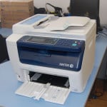
Xerox WorkCentre 6015 — внешний вид
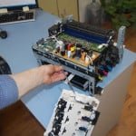
Не смотря на заголовок, инструкция подходит и для Xerox Phaser 6000 / 6010. Отличие только в снятии ряда элементов кожуха. Принтер изначально создавался как одноразовый, поэтому и разбор принтера осуществляется долго и нудно. Вообще, разбор и ремонт аппарата — это что-то среднее между ремонтом телефона или ремонтом часов. То есть, если раньше вам доводилось самостоятельно разбирать часы, а потом вы не могли их собрать, то лучше и не начинайте самостоятельный ремонт этого аппарата. Из инструментов понадобится плоская и крестовая отвертка.
Этап №1 Снятие элементов кожуха
Декоративная накладка
 Прежде всего необходимо снять элементы кожуха. У большинства принтеров и МФУ разбор начинается с задней части. Но в новой линейке домашних принтеров Xerox 6000/3010 разбор начинается именно с передней части (как в canon 4018). Для начала отщелкиваем синюю декоративную накладку (она полностью держится на пластиковых защелках). По-первой, панель отщелкивали с помощью плоской отвертки, но в последующих ремонтах просто руками.
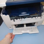
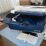
Откидной лоток
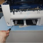
Фиксирующие шурупы
Перед снятием передней панели полностью, нужно удалить откидной лоток для бумаги и открутить фиксирующие шурупы. Лоток отсоединяется очень просто: для этого просто отожмите его с одного края и выщелкните . После того, как отсоедините лоток, станут доступны два фиксирующих шурупа, которые необходимо открутить.
Переняя панель
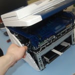
Вид МФУ со снятой передней панелью
После того, как шурупы были успешно выкручены, потянув за край отщелкните переднюю панель. Кстати, в аппарате передние панели играю сугубо декоративные функции, и печать вполне успешно может осуществляться и со снятыми панелями (что весьма полезно во время тестирования принтера, после устранения недостатков).
Левая панель
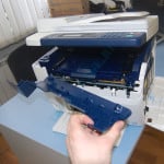
Основные фиксирующие защелки
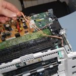
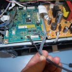
Теперь демонтируйте левую боковую панель. Панель полностью фиксируется на защелках, без шурупов. Рекомендуем сначала отщелкнуть нижние защелки (см. фото справа), так как именно они являются основными фиксирующими элементами. Внимание!! Отщелкивая панель, будьте предельно аккуратны и внимательны, так как сразу за левой панелью скрывается плата форматора, которую по неосторожности можно повредить.
Провода и шлейфы сканера от форматора
Провод заземления
Далее необходимо демонтировать верхний блок сканера. Для этого необходимо отсоединить от платы форматора провода и шлейфы, идущие на сканер. Выдерните два шлейфа, идущие на линейку сканирования и блок АДФ, далее отсоедините кабель панели управления и открутите черный провод заземления. Отсоединяя провода и шлейфы, не прилагайте излишнее усилие. Это может привести к поломке разъемов.
Левый кронштейн сканера
Демонтаж блока сканера
Отсоединив провода, идущие к блоку сканера, приступаем к снятию блока сканера. Для начала отщелкните левый и правый кронштейны, удерживающие сканер, и, подняв сканер вверх, извлеките его. Внимание!! Вынимая сканер, будьте предельно внимательны, не повредите провода и шлейфы. Лучше всего при демонтаже сканера привлечь на помощь еще одного человека.
Извлечение фиксирующих шурупов
Демонтаж верхней части
Снятие блока сканера, пожалуй, самая трудоемкая процедура. Отсоедините верхнюю часть корпуса. Для этого открутите четыре фиксирующих шурупа и извлеките его, потянув вверх. Демонтируя верхнюю часть корпуса, обратите внимание как он посажен (это несколько облегчит последующую сборку).
Извлечение провода датчика закрытия дверцы
Кабель датчика закрытия дверцы
Далее необходимо снять заднюю часть аппарата. Прежде чем это сделать, нужно отсоединить кабель датчика закрытия дверцы от платы блока питания. Внимание!! Вытаскивая кабели из разъемов, старайтесь запоминать, куда именно они были воткнуты и как были уложены. Извлекая провод из проложенной трассы, постарайтесь не повредить уложенный параллельно с ним шлейф.
Шурупы, фиксирующие заднюю стенку
Извлечение задней стенки, обратите внимание на защелки слева
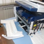
Крепление датчиков к кожуху — не самый лучший вариант и, как правило, производители так не поступают. Однако, учитывая тот факт, что принтер изначально разрабатывался как одноразовый, то разработчикам это простительно. Отсоединив кабель датчика, открутите фиксирующие шурупы и извлеките заднюю стенку. Внимание!! Задняя стенка фиксируется не только на шурупах, но и на весьма жестких боковых защелках.
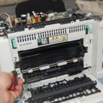
Извлечение силового кабеля узла термозакрепления
Боковая декоративная крышка
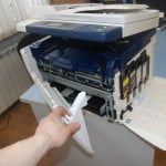
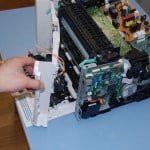
Осталось снять последнюю часть корпуса — правую боковую стенку. Прежде чем приступить к демонтажу правой стенки, нужно извлечь из блока питания силовой разъем, идущий на печку, так как его трасса пролегает через боковую стенку. Далее отщелкните боковую декоративную крышку (естественно, предварительно удалив все картриджи).
Шурупы, выделенные маркером
Черный держатель
Открутите фиксирующие шурупы (но только те, которые на фото обведены маркером!). Шурупы, которые не обведены, относятся к блоку ксерографии и их пока откручивать не нужно. Далее отщелкните черный держатель. Внимание!! Держатель отщелкивается с трудом, и сначала создается ощущение, что он прикручен скрытым шурупом.
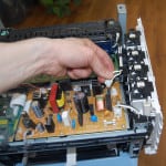
Снятие правой боковины
Внимание!!! будьте предельно аккуратны и не повредите провода
Приступаем к демонтажу последней части кожуха. Эта часть фиксируется только на шурупах. Поэтому после того, как открутили шурупы, отсоедините правую боковину, потянув за правый край. Внимание!! Правая боковина содержит механизм подкачки тонера, поэтому при извлечении будьте предельно аккуратны и не повредите провода.
Извлечение проводов из проложенной трассы
Извлечение проводов из разъемов на плате.
Отсоединив правую боковину, нужно извлечь провода из проложенной трассы и вытащить провода из разъемов. Извлечение проводов из разъемов — это целое искусство, требующее немалой сноровки. Поэтому, если какой либо провод не вытаскивается, не нужно выдирать его с мясом, а просто включите смекалку. На этом снятие кожуха закончено, но это еще только самое начало. Как в мультике «Не готово? Что ж такого – стрижка только начата!»
![]() Загрузка…
Загрузка…
- Информация о материале
- Категория: БАЗА ЗНАНИЙ
-
Просмотров: 2812
В общем ничего необычного, свойственно для данной модели МФУ, на сколько я понял, в чип вшито определенное количество копий, которое должен печатать картридж, при достижении этого количества, надо менять тонер. Меняешь чип, тонер, ошибка пропадает. Смущает то, что качество печати отличное, вроде как, рано еще менять тонер.
На просторах интернета нашел решение, позволяющее оттянуть замену чипа / тонера / картриджа. Последовательность действий такая.
— Выключаю МФУ
— Наклоняю корпус МФУ назад. примерно на 90 градусов
— Включаю МФУ, жду, когда пройдет инициализация, вижу, что на табло нет ошибки
— Опускаю МФУ горизонтально
— МФУ печатает какое-то время, при появлении ошибки повторяю процедуру.
В итоге, поставил МФУ в наклоненном состоянии, печатал так.