
Современные копировальные аппараты Xerox отличаются качество, надежностью и «быстрым» стартом. Также у них существует множество особенностей, которые отличают их от принтеров других производителей. Например, используется тефлоновый вал, а не термопленка.
Однако избегать различных поломок и ошибок пока не удается ни одному устройству. К самым частым неисправностям у принтеров Xerox относятся: залипание или повреждение датчика бумаги, повреждение роликов подачи, часто требуется перепрошивка программного обеспечения.
Если у вас возникнут вопросы насчет того, как исправить код ошибки копировального аппарата Xerox, то вы можете обратиться к специалистам нашего сервисного центра.

Основные коды ошибок копировальных аппаратов Xerox и способы их устранения:
- Коды ошибок Xerox 1012, 1012(RE)
- Коды ошибок Xerox 1020
- Коды ошибок Xerox 1025
- Коды ошибок Xerox 1035
- Коды ошибок Xerox 1038
- Коды ошибок Xerox 2830
- Коды ошибок Xerox 5011, 5012, 5014
- Коды ошибок Xerox 5016, 5017, 5316, 5317
- Коды ошибок Xerox 5018, 5028
- Коды ошибок Xerox 5312, 5313, 5314
- Коды ошибок Xerox 5318, 5320, 5322
- Коды ошибок Xerox 5328
- Коды ошибок Xerox 5330
- Коды ошибок Xerox 5340, 5343
- Коды ошибок Xerox 5345
- Коды ошибок Xerox 5350, 5352
- Коды ошибок Xerox 5355
- Коды ошибок Xerox 5622
- Коды ошибок Xerox XC520, 540, 560, 580
Xerox 1012, 1012(RE)
| Код ошибки | Описание |
|---|---|
| E1 | Jam between paper feed and fuser |
| E3 | Jam in fuser |
| E5 | Clam shell open |
| E6 | Paper feed section cover is open |
| J1 | Toner cartridge near empty |
| J3 | Drum cartridge not seated properly |
| J7 | Waste toner full (replace drum cartridge) |
| L6 | Key counter out |
| L8 | Exposure area overheat |
| U1 | No clock pulse (drive problem) |
| U2 | Scan problem |
| U3 | Lens/mirror problem (RE model only) |
| U4 | Heat problem |
| U8 | Exposure lamp control circuit problem |
Xerox 1020
| Код ошибки | Описание |
|---|---|
| LL | Probable bad heater lamp |
Xerox 1025
| Код ошибки | Описание |
|---|---|
| A1 | DF jam |
| C1 | PF jam cass. 1 |
| C2 | PF jam cass. 2 |
| C3 | PF jam cass. 3 |
| C9 | Bypass jam |
| E1-1 | Paper jam before exit switch |
| E1-2 | Paper jam |
| E1-5 | Paper jam |
| E1-6 | Paper jam |
| E3-3 | Paper jam at exit switch |
| E3-4 | Paper jam at exit switch |
| E5 | Front door open |
| F1 | Collator jam |
| F5 | Collator interlock |
| F8 | No power to collator |
| F9 | Collator bin home switch |
| J7 | 250 copies since toner waste was full |
| L5 | Original cass. not present after clearing interrupt |
| L6 | Key counter |
| L8 | Platen glass too hot |
| U1 | Main motor clock pulse |
| U2 | Scan problem |
| U3-1 | Lens problem |
| U4-1 | Open thermistor |
| U4-2 | Low temperature |
| U4-4 | Temperature |
| U4-5 | Main PWB |
| U6-1 | Main PWB |
| U6-2 | Main PWB |
| U6-3 | Main board battery |
| U6-4 | Initialization |
| U8 | Exposure lamp |
Xerox 1035
| Код ошибки | Описание |
|---|---|
| A9 | Scanner location |
| C1 | Paper feed — upper cassette |
| C2 | Paper feed — lower cassette |
| C9 | Bypass jam |
| E5 | Clam shell is open |
| L6 | Key counter |
| U1 | Off/On |
| U2 | Optics |
| U4 | Low fuser temperature |
Xerox 1038
| Код ошибки | Описание |
|---|---|
| A1 | DF jam |
| C1 | PF jam cass. 1 |
| C2 | PF jam cass. 2 |
| C3 | PF jam cass. 3 |
| C9 | Bypass jam |
| E1-1 | Paper jam before exit switch |
| E1-2 | Paper jam |
| E1-5 | Paper jam |
| E1-6 | Paper jam |
| E3-3 | Paper jam at exit switch |
| E3-4 | Paper jam at exit switch |
| E5 | Front door open |
| F1 | Collator jam |
| F5 | Collator interlock |
| F8 | No power to collator |
| F9 | Collator bin home switch |
| J7 | 250 copies since toner waste was full |
| L5 | Original cass. not present after clearing interrupt |
| L6 | Key counter |
| L8 | Platen glass too hot |
| U1 | Main motor clock pulse |
| U2 | Scan problem |
| U3-1 | Lens problem |
| U4-1 | Open thermistor |
| U4-2 | Low temperature |
| U4-4 | Temperature |
| U4-5 | Main PWB |
| U6-1 | Main PWB |
| U6-2 | Main PWB |
| U6-3 | Main board battery |
| U6-4 | Initialization |
| U8 | Exposure lamp |
Xerox 2830
| Код ошибки | Описание |
|---|---|
| A9 | Scanner location |
| C1 | Paper feed — upper cassette |
| C2 | Paper feed — lower cassette |
| C9 | Bypass jam |
| E5 | Clam shell is open |
| E5 | Clam shell open |
| L6 | Key counter |
| U1 | Off/On |
| U2 | Optics |
| U4 | Low fuser temperature |
Xerox 5011, 5012, 5014
| Код ошибки | Описание |
|---|---|
| C8 | Bypass jam/no paper |
| C9 | Bypass jam |
| E1 | Jam |
| E3 | Fuser jam |
| E5 | Clamshell open |
| E6 | PF section cover open |
| J1 | Toner cartridge amost empty |
| J3 | Copy cart (drum unit) missing/not seated right |
| J7 | Copy cartridge has run 18,000 copies |
| J8 | Copy cartridge. Improperly seated or possible only one of two fuses in the cartridge blew |
| L6 | Key counter |
| L8 | Exposure glass too hot |
| U1 | Drive problem |
| U2 | Scan problem |
| U3 | Lens or mirror drive problem |
| U4 | Fuser problem. Heat lamp, thermoswitch, SSR, thermistor |
| U6 | Battery on main board |
| U8 | Exposure lamp or exposure lamp circuit |
Xerox 5016, 5017, 5316, 5317
| Code | Description |
|---|---|
| A1-1 | Document feeder feed jam |
| A1-2 | Document feeder belt jam |
| A2-1 | Document feeder exit jam |
| A2-2 | Duplex jam |
| A3 | DAD interlock |
| A5 | Duplex and DAD right side interlock |
| A6 | Copier jams after |
| A9 | Document feed belt drive motor |
| C1-3 | Top cassette misfeed |
| C2-3 | Middle cassette misfeed |
| C3-3 | Bottom cassette misfeed |
| C9-3 | Bypass misfeed |
| E1-11 to E1-14 | Paper jam in machine. Did not reach exit switch soon enough |
| E1-6 | Paper path jam |
| E3-31 to E3-34 | Exit switch jam |
| E3-6 | Fuser jam |
| E5 | Front door interlock |
| E6 | Right side interlock or TTM interlock |
| F1 | Sorter jam |
| F5 | Sorter interlock |
| F8 | Sorter board to copier main board communication problem |
| F9 | Sorter bins |
Xerox 5018, 5028
| Code | Description |
|---|---|
| A1 | Document is ADF |
| A1-8 | Main board received reset signal |
| A2 | ADF jams |
| A6, A7 | ADF jams |
| A9 | ADF jams |
| C1 — C4 | Feed jam |
| C5-1 to C5-4 | Jams in various areas |
| C5-2 | Jams in various areas |
| C5-3 | Jams in various areas |
| C5-4 | Duplex jam |
| E0 | Machine has reset |
| E1 | Jam |
| E1-E0 | Registration jam |
| E1-E5 | Clamshell interlock |
| E1-E6 | Right side interlock |
| E1-E7 | Two tray interlock |
| E1-E8 | Sorter interlock |
| E1-E9 | Copy cartridge interlock |
| E2 | Reset signal happened |
| E3 | Jam |
| E4 | Exit jam |
| E4-10 | Exit jam |
| E4-5 | Clamshell interlock |
| E4-6 | Right side interlock |
| E4-7 | Two tray interlock. Duplex interlock |
| E4-8 | Sorter interlock |
| E4-9 | Copy cartridge interlock |
| E5 | Clamshell interlock |
| E6 | Right side interlock |
| E7 | Duplex interlock |
| E9 | Copy cartridge interlock |
| F3-1 | Sorter bin home switch |
| F3-2 | Sorter cam switch |
| F3-3 | Sorter cam switch |
| J1-1 | Add toner |
| J1-2 | Temporary low toner signal |
| J2-0 | Replace copy cartridge |
| L2 | 2000 copies left on copy cartridge |
| L3 | ADF to machine communication problem |
| L4 (flashing) | 1000 copies left on fuser web |
| rr | Bad EPROM on main board |
| U0 | Main board |
| U2 | Scan problem |
| U2-1 | Scan home |
| U3-00 | Cam drive problem |
| U3-01 | Cam movement slow |
| U3-04 | Main board to duplex communication |
| U3-09 | Cam problem |
| U3-12 | Jogger problem |
| U3-19 | Cam problem |
| U3-21 | Cam problem |
| U3-23 | Cam problem |
| U3-29 | Cam problem |
| U3-32 | Cam problem |
| U3-34 | Cam problem |
| U3-39 | Cam problem |
| U3-43 | Cam problem |
| U3-45 | Cam problem |
| U3-49 | Cam problem |
| U3-54 | Cam problem |
| U3-56 | Cam problem |
| U3-59 | Cam problem |
| U4-1 | Fuser problem. Long warm up |
| U4-2 | Low fuser temperature after warm up |
| U4-3 | High fuser temperature |
| U4-4 | Open fuser thermistor |
| U4-6 | Replace fuser web |
| U4-7 | Thermistor signal problem |
| U7-1 | Copy cartridge belt drive problem |
| U9-3 | Exposure lamp problem |
| U9-4 | Toner motor |
| U9-5 | Problem in warm up |
Xerox 5312, 5313, 5314
| Код ошибки | Описание |
|---|---|
| C1 | Upper paper feed problem. Did not reach feed sensor |
| C2 | Lower paper feed problem. Did not reach feed sensor |
| E1 | Exit jam. Paper did not reach exit sensor |
| E3 | Exit jam. Paper still on exit sensor |
| J1 | Add toner |
| J3 | Copy cartridge (drum unit) not installed |
| J7 | Copy cartridge (drum unit) must be replaced |
| J8 | Copy cartridge (drum unit) problem |
| L6 | Problem with an accessory. Installed but not initialized |
| U1 | Drive problem. Main motor, gear etc. |
| U2 | Scan problem |
| U3 | Main board dip switches wrong. Lens drive problem |
| U4 | Fuser problem. Heat lamp, thermal switch, overheat, thermistor. |
| U6 | EPROM error |
| U8 | Auto exposure sensor. No exposure lamp or weak lamp |
Xerox 5318, 5320, 5322
| Code | Description |
|---|---|
| A1-11 | Original ready switch |
| A1-12 | Feed sensor |
| A1-1 to A1-32 | All indicate a paper path problem, etc. in the ADF |
| A1-21 | Original ready switch and document registration sensor or both the document feed sensor and document registration sensor |
| A1-22 | ADF registration sensor |
| A1-23 | Original did not reach ADF registration sensor quickly enough |
| A1-24 | ADF sensor stuck down too long |
| A1-25 | ADF sensor actuated at the wrong time during single sheet feed |
| A1-26 | ADF sensor not actuated quickly enough in sheet feed mode |
| A1-31 | In reverse, ADF sensor is not actuated soon enough |
| A1-32 | In reverse, ADF sensor is actuated too long |
| A2 | ADF exit problems |
| A2-1 | Original ready sensor and ADF exit switch are actuated or ADF feed in sensor and ADF exit switch are both actuated |
| A2-2 | ADF exit switch |
| A2-3 | ADF exit switch is not actuated on time |
| A3 | Irregular size documents |
| A3-1 | Wrong size original sensed in 1:1 mode |
| A3-2 | Wrong size original sensed in the 2:1 mode |
| A5 | ADF interlock |
| A5 | ADF interlock |
| A6 | ADF single sheet document reset. |
| A6-1 | Reset original |
| A6-2 | Reset sheet feeder |
| A7 | Document cover interlock |
| A8 | ADF exit interlock |
| C1 | Tray 1 jam |
| C1-2 | Paper feed problem in tray 1 |
| C1-3 | Paper does not reach registration |
| C2 | Tray 2 jam |
| C3 | Tray 3 jam |
| C3-1 | Paper feed problem from tray 3 |
| C3-2 | Paper feed problem from tray 3 |
| C3-3 | Paper feed problem from tray 1 |
| C6-1 | Duplex paper feed problem |
| C6-2 | Duplex and/or tray 1 paper feed problem |
| C6-3 | Paper feed problem from tray 1 |
| C7-1 | Paper feed problem from HCF |
| C7-2 | Paper feed problem from HCF on tray 1 |
| C7-3 | Paper feed problem from tray 1 |
| C8 | Paper stays in tray or duplex or HCF |
| C8-1 | Paper on tray 1 feed sensor |
| C8-2 | Paper on tray 2 feed sensor |
| C8-3 | Paper on tray 3 feed sensor |
| C8-4 | Paper on HCF feed sensor |
| C8-5 | Paper in duplex section |
| C9 | Bypass feed problem |
| C9-3 | Paper from bypass did not reach registration sensor quickly enough |
| E1-10 to E1-25 | Internal jam |
| E1-6 | Paper on registration sensor |
| E2 | Reset signal happened. Might read E-2 something else. |
| E3-30 to E4-14 | Exit jam |
| E3-30 to E3-35 | Exit switch actuated too long |
| E3-6 | Exit jam |
| E3-6 | Paper on exit switch |
| E4-10 to E4-14 | Inverter sensor not actuated. |
| E4-10 to E4-45 | Paper did not reach inverter switch soon enough |
| E4-15 | Inverter sensor |
| E4-40 to E4-45 | Duplex entry sensor |
| E4-6 | Paper on inverter switch |
| E4-6 | Inverter sensor |
| E5 | Front door interlock |
| E6-1 | Tray 1 interlock |
| E6-2 | 2 tray or duplex interlock |
| E6-3 | HCF interlock |
| E7-2 | Duplex inverter interlock |
| E7-3 | Duplex interlock |
| E8-10 to E8-15 | Paper on duplex feed sensor is not actuated soon enough |
| E8-6 | Paper in duplex |
| E8-6 to E8-15 | Duplex entry sensor |
| F1-1 | Paper did not reach sorter |
| F1-2 | Paper stayed on sorter feed sensor |
| F1-6 | Sorter exit sensor |
| F3 | Paper size not available for sort/stack |
| F5 | Sorter interlock |
| H2-1 | Communication problem between main board and duplex board |
| H2-2 | Side guard sensor problem |
| H3-1 | Communication problem between main board and HCF |
| H3-2 | Upper limit sensor problem on HCF |
| H6-1 | ADF size sensor |
| H6-2 | ADF nudgeer sensor |
| H6-3 | Belt drive motor does not have 24 volts. Black toner is empty, but 100 copies have been run without changing toner |
| J1 | Black toner is empty, but 100 copies have been run without changing toner |
| J3 | Replace copy cartridge |
| J3 | No copy cartridge (drum unit) |
| J7 | Copy cartrige must be replaced |
| J8-1 | Wrong copy cartridge installed |
| J8-2 | Copy cartridge EEPROM must be changed |
| L6 | Auditron or other counter problem |
| L6 | Key counter not installed |
| L8 | Platen glass temperature is too high |
| L9 | Communication problem between interimage erase/edge lamps and main board |
| U1-1 | Main motor drive problem |
| U2-1 | Scan home problem |
| U2-1 to U2-4 | Scan home sensor |
| U2-2 | Scan home problem or optics problem |
| U2-3, U2-4 | Scan home problem |
| U3-1 | Lens sensor problem |
| U4-1 | Fuser thermistor open |
| U4-2 | Fuser did not warm up properly |
| U4-3 | Fuser temperature too high |
| U4-4 | Fuser problem. Staying on too long |
| U4-6 | High fuser temperature |
| U5-1 | Sorter bin home switch not activated |
| U5-2 | Sorter bin home switch stayed actuated |
| U5-3 | Sorter bin home switch |
| U5-4 | Sorter bin home switch |
| U6-1 | ROM problem |
| U6-2 | RAM problem |
| U6-3 | Low battery |
| U6-4 | Incorrect value in NVM. Reinitialize main board with code 20-96 |
| U8-1 | Exposure lamp problem |
| U8-2 | Communication problem main board and exposure board |
| U8-3 | Exposure lamp or exposure lamp board problem |
| U8-4 to U8-6 | Problem with exposure lamp, lamp sensor, lamp board |
Xerox 5328
| Code | Description |
|---|---|
| A1 | Document in ADF |
| A1-8 | Main board received reset signal |
| A2 | ADF jams |
| A6 | ADF registration jam |
| A7 | ADF interlock |
| A9 | Tray 1 jam |
| C1 | Tray 2 jam |
| C2 | Tray 3 jam |
| C3 | Bypass feed jams |
| C4 | Machine has reset |
| E1 | Jam |
| E1-5 | Clamshell interlock |
| E1-6 | Right side interlock |
| E1-7 | Two tray interlock, or duplex interlock |
| E1-8 | Sorter interlock |
| E1-9 | Copy cartridge interlock |
| E1 or E1-0 | Registration jam |
| E2 | Reset signal happened |
| E3 | Jam in transfer area |
| E4 | Exit jam |
| E4-0 | Exit jam |
| E4-5 | Clamshell interlock |
| E4-6 | Right side interlock |
| E4-7 | Two tray interlock |
| E4-8 | Sorter interlock |
| E4-9 | Copy cartridge interlock |
| E5 | Clamshell interlock |
| E6 | Right side interlock |
| E9 | Copy cartridge interlock |
| F3-1 | Sorter bin home switch |
| F3-2 | Sorter cam switch |
| F3-3 | Sorter cam switch |
| F5 | Sorter interlock |
| J1-1 | Add toner |
| J1-2 | Temporary low toner signal |
| J2-1, J2-2 | Replace copy cartridge |
| J5, J6 | ADF to machine communications problem |
| L2 | 2000 copies left on cartridge |
| L3 | ADF to machine communications problem |
| L4 | (flashing) 1000 copier left on fuser web |
| L6 | Auditron or other counter problem |
| LL | Main board. Try simulation 1.1 to initialize |
| rc | Wrong operation panel installed |
| rr | Bad EPROM on main board. Try 1.1 |
| U0 | Main board |
| U2 | Scan problem |
| U2-1 | Scan home |
| U2-2 | Scan home or scan encoder |
| U2-4 | Scan home or scan dual page sensor |
| U2-7 | Scan home |
| U4-1 | Fuser problem. Long warm up |
| U4-2 | Low fuser temperature after warm up |
| U4-3 | High fuser temperature |
| U4-4 | Open fuser thermistor |
| U4-6 | Replace fuser web. |
| U4-7 | Thermistor signal problem |
| U7-1 | Copy cartridge belt drive problem |
| U9-3 | Exposure lamp problem |
| U9-4 | Toner motor |
| U9-5 | Problem in warm-up |
Xerox 5330
| Code | Description |
|---|---|
| A1-1 to A1-32 | All indicate a paper path problem, etc. in the ADF. |
| A2 | ADF exit problems |
| A3 | Irregular size documents |
| A5 | ADF interlock |
| A6 | ADF single sheet document reset. |
| A7 | Platen interlock |
| A8 | ADF exit interlock |
| C1 | Tray 1 jam |
| C2 | Tray 2 jam |
| C3 | Tray 3 jam |
| C6-1, C6-2 | Jams related to duplex |
| C6-3 | Registration sensor, re tray 1 |
| C7-1, C7-2 | HCF feed problems |
| C7-3 | Tray 1 feed problem |
| C8 | Paper stays in tray or duplex or HCF |
| C9 | Bypass feed problem |
| E1-10 to E1-25 | Internal jam |
| E1-6 | Paper on registration sensor |
| E2 | Reset signal happened. Might read E-2 something else. |
| E3-30 to E4-14 | Exit jam |
| E3-6 | Exit jam |
| E4-10 to E4-14 | Inverter sensor not actuated. |
| E4-15 | Inverter sensor |
| E4-40 to E4-45 | Duplex entry sensor |
| E4-6 | Inverter sensor |
| E5 | Front door interlock |
| E6-1 | Tray 1 interlock |
| E6-2 | 2 tray or duplex interlock |
| E6-3 | HCF interlock |
| E7-2, E7-3 | Duplex interlock |
| E8-6 to E8-15 | Duplex entry sensor |
| F1-1 | Sorter entry sensor |
| F1-6 | Sorter exit sensor |
| F3 | Paper size not available for sort/stack |
| F5 | Sorter interlock |
| J1 | Add toner |
| J3 | Replace copy cartridge |
| J7 | Replace copy cartridge |
| J8-1 | Wrong copy cartridge installed |
| J8-2 | Copy cartridge EEPROM |
| L6 | Auditron or other counter problem |
| L8 | Platen glass temperature is too high |
| L9 | Communication problem between interimage erase/edge lamps and main board |
| U1-1 | Main motor drive problem |
| U2-1 to U2-4 | Scan home sensor |
| U3-1 | Lens sensor |
| U4-1 | Open fuser thermistor |
| U4-2 | Fuser did not warm up properly |
| U4-3 | Fuser temperature too high |
| U4-4 | Fuser problem. Staying on too long |
| U4-6 | High fuser temperature |
| U5-1 | Sorter bin home switch not activated |
| U5-2 | Sorter bin home switch stayed actuated |
| U5-3 | Sorter bin home switch |
| U5-4 | Sorter bin home switch |
| U6-1 | ROM problem |
| U6-2 | RAM problem |
| U6-3 | Low battery |
| U6-4 | Incorrect value in NVM. Reinitialize main board with code 20-96 |
| U8-1 to U8-6 | Problem with exposure lamp, lamp sensor, lamp board |
Xerox 5340, 5343
| Code | Description |
|---|---|
| 00-009; 030 to 033 | A door was opened while paper was being fed |
| 00-047 | Paper in duplex |
| 00-1 | Auditron |
| 00-2 | Diagnostic error |
| 00-3 | Faults error |
| 00-4 | Ric error |
| 00-5 | Job manager system error |
| 00-6 | LLM interface |
| 00-7 | Standby error |
| 00-8 | Communications error |
| 00-9 | Xerographic error |
| 01-300 | Front interlock |
| 01-310 | Right upper interlock |
| 01-315 | Left upper interlock |
| 01-320 | Left lower interlock |
| 01-325 | Fuser interlock |
| 02-910 | Key counter missing |
| 02-920 | Wrong combination of accessories |
| 03-321, 322, 326, 327 | LLM to ISIL communications problems |
| 03-328 | IOT communications problem with duplex or tray 4 |
| 03-330 | IOT communications problems with HCF |
| 03-335, 03-336 | LLM communications problems with edit |
| 03-340 | NVM memory |
| 03-341, 03-347 | Communications problems between IOT and sorter |
| 03-350, 03-354 | Communications problem with LLM and user interface |
| 03-363, 03-364 | Communications problem between LLM & optics |
| 03-370, 03-373 | Communications problem between LLM & DADF |
| 03-380, 384 | |
| 03-416, 03-422 | RAM memory problem |
| 03-424, 426 | NVM memory problem |
| 03-430, 432 | Billing problem |
| 03-439 | GRAIB communications problem |
| 03-440 | RIC communications problem |
| 03-441 | RIC NVM problem |
| 03-442 | Modem |
| 03-443, 03-458 | RIC problems |
| 03-460 | Serial communications processor problem |
| 04-300 | Main motor or drive problem |
| 05-100, 05-108 | DADF registration sensor |
| 05-110 | DADF exit sensor |
| 05-115, 120 | DADF jams |
| 05-305 | DADF document drive |
| 05-310, 312 | DADF document sensor |
| 05-316 | DADF registration sensor jam |
| 05-325 | DADF exit sensor |
| 05-335, 341, 345 | DADF interlock switches |
| 06-300, 06-310 | Scan problems |
| 06-315 | Scan drive |
| 06-320A, 320B, 320C, 325 | Scan problem |
| 06-330 | Lens drive |
| 06-340 | Exposure control problem |
| 06-342 | LLM CPU problem |
| 06-344, 06-350 | Exposure cvontrol problem |
| 06-352 | IOT CPU problem |
| 07-300, 315, 330, 345 | Tray faults |
| 07-360, 07-370 | HCF problems |
| 07-375, 380A, 380B | Duplex problems |
| 08-100, 08-110 | Feed problems. Lead edge of copy paper is late getting to feed sensor of tray 1 |
| 08-115, 08-162 | Feed problem. Lead edge of copy paper is late getting to registration sensor |
| 08-165 | Paper jam at registration sensor |
| 08-310, 08-370 | Paper at a sensor when power is turned on |
| 08-330 | DADF nudger sensor |
| 08-380 | Registration side to side problem with home position |
| 08-390 | Nip |
| 09-300 | Copy cartridge finished (drum unit) |
| 09-310 | Add black toner Add color toner |
| 09-320 | Add color toner |
| 09-330 | Wrong copy cartridge (wrong drum unit) |
| 09-340 | Drum cartridge not installed properly |
| 09-350 | Waste toner full |
| 100 | A fault has occurred |
| 10-100 | Exit jam |
| 10-105 | Exit jam |
| 10-110 | Vertical sensor jam |
| 10-120, 122, 125 | Duplex jam |
| 10-150, 155 | Too much or not enough paper in duplex tray |
| 10-300 | Fuser thermistor |
| 10-302 | Low fuser temperature |
| 10-304 | Bad fuser temp |
| 10-308 | High fuser temperature or open thermistor |
| 10-310 | High fuser temperature |
| 10-312 | Fuser not up to temperature after energy save |
| 10-314 | Fuser problem |
| 10-320 | Fuser web finished |
| 10-330, 335, 340 | Exit switch, vertical sensor switch actuated when power is turned on |
| 11-100, 11-116 | Sorter jam |
| 11-150, 11-176 | Sorter auto stapler jam |
| 11-310, 314, 316 | Sorter interlock |
| 11-325A, B, C, D, E, F, G | Sorter index |
| 11-352, 354, 356 | Sorter auto stapler interlocks |
| 11-365A, B, C, D, E | Sorter auto stapler bin |
| 11-370, 371, 372A, 373A, 373B, 374 | Sorter auto stapler staple failure, staple home problem or tamper home problem |
| 11-385A, 385B, 390A,B,C,D,E, 396A | Sorter auto stapler staple failure, staple home problem or tamper home problem |
| 301 | Fuser web must be replaced |
| 302 | Copy cartridge (drum unit) must be replaced |
| 501 | Tray 1 must be rebuilt |
| 502 | Tray 2 must be rebuilt |
| 503 | Tray 3 must be rebuilt |
| 504 | Tray 4 must be rebuilt |
| 505 | HCF must be rebuilt |
| 506 | Bypass must be rebuilt |
| 507 | Duplex unit must be rebuilt |
| 508 | Replace black developer |
| 509 | Replace red developer |
| 510 | Replace green developer |
| 512 | Replace brown developer |
| 513 | Copy cartridge (drum unit) will need replacing soon |
| 514 | Fuser web will need replacing soon |
| 515 | DADF belt should be replaced |
| 516 | DADF feed rollers should be replaced |
| 517 | Replace exposure lamp |
| 518 | Replace suction filter |
| 519 | Replace ozone filter |
| 520 | Replace optics filter |
| 521 | Replace particle filter |
| 522 | Replace upper fuser roller |
| 523 | Replace fuser pawls |
| 524 | Replace pressure roller |
| 525 | Replace pressure roller pawls |
| 900-905 | Key operator calls |
Xerox 5345
| Код ошибки | Описание |
|---|---|
| 01-01 | Frequency monitoring and zero cross problem |
| 01-02 | Interlock |
| 01-03 | AC power problem |
| 01-04 | Finisher interlock |
| 01-05 | 24v problem |
| 03-01 | Optics to main board communication problem |
| 03-02 | Software reset problem |
| 03-03 | Could be punched holes in the lead edge of the original |
| 03-04 | Software problem |
| 03-06 | Low battery |
| 03-07 | NVM not initialized or is missing or defective |
| 03-17 | Communication problem between main board and finisher board |
| 03-18 | Initializes one NVM counter to agree to others |
| 03-19 | All three NVM counter to agree with others |
| 03-20 | Main board/interface board problems |
| 03-21 | Problem with RIC NVM |
| 03-22 | RIC modem problem |
| 03-23 | RIC real time clock failure. |
| 03-25 | RIC NVM problem or not initialized |
| 03-27 | NVM problem |
| 03-28 | Watchdog software problem |
| 03-29 | Microprocessor crystal not at correct frequency |
| 03-30 | No software response from finisher after 20 seconds have elapsed |
| 06-01 | Lens did not reach 1.1 position |
| 06-02 | 1/2 rate scanner problem |
| 06-03 | Scan home problem |
| 06-04 | Scan home problem |
| 06-05 | Scan home problem |
| 06-06 | Scan encoder |
| 06-07 | Scan encoder |
| 06-08 | Scan drive boost |
| 06-09 | Scan encoder |
| 06-11 | Scan encoder pulse phases |
| 06-12 | Insufficient scan damping |
| 07-01 | Duplex tray not home during duplexing |
| 07-02 | Tray 2 not home when selected |
| 07-13 | Tray 2 height sensor problem |
| 07-15 | Tray 2 empty |
| 07-16 | Tray 1 door open |
| 07-18 | Tray 1 stack sensor |
| 07-22 | Tray 1 empty |
| 07-26 | Tray 1 bypass switch actuated too long |
| 07-27 | Tray 1 bypass switch deactuated too early |
| 07-30 | Paper in duplex |
| 07-31 | Paper in duplex |
| 07-32 | Duplex tray empty, when paper should be there |
| 08-10 | Paper did not reach tray 2 input tray sensor |
| 08-11 | Paper did not reach duplex input sensor |
| 08-12 | Paper did not reach tray 1 |
| 08-14 | Paper did not leave tray 2 input sensor quickly enough |
| 08-18 | Trail edge did not reach tray 2 input sensor quickly enough |
| 08-19 | Trail edge did not reach tray 1 input sensor quickly enough |
| 08-20 | Paper in duplex |
| 08-21 | Paper in tray 2 input |
| 08-22 | Paper in tray 2 or duplex at wrong time |
| 08-23 | Paper at tray 1 input at wrong time |
| 08-24 | Paper in tray 1 at wrong time |
| 08-28 | Upper and lower nips problem |
| 09-08 | Low toner condition |
| 09-12 | Drum signals are out of range |
| 09-13 | Unstable drum patch readings |
| 09-15 | Patch is too dark |
| 09-16 | Patch is too light |
| 09-17 | Open toner container access cover |
| 09-18 | Low toner level |
| 09-21 | Low toner sensor disconnected |
| 09-22 | Low toner condition, even after machine has been theoretically, adding toner |
| 10-02 | Low fuser temperature |
| 10-03 | High fuser temperature |
| 10-06 | Paper did not reach out put switch |
| 10-07 | Paper stayed on output switch |
| 10-10 | Paper did not reach decurler sensor |
| 10-11 | Paper did not reach decurler sensor |
| 10-12 | Paper on decurler sensor |
| 10-13 | Paper did not reach duplex entry sensor in time |
| 10-14 | Paper did not reach duplex entry sensor in time |
| 10-15 | Paper on entry sensor at wrong time |
| 10-17 | Fuser temperature is too high and fuser relay has deactuated |
| 12-01 | Paper at finisher input sensor |
| 12-02 | Paper did not reach finisher |
| 12-03 | Paper reached finisher too soon |
| 12-05 | Paper at stapler |
| 12-06 | Paper at stapler |
| 12-07 | Paper did not reach stapler |
| 12-08 | Paper did not reach stapler |
| 12-10 | Complied motor not working properly |
| 12-15 | Eject motor problem and/or eject encoder |
| 12-20 | Stacker motor problem |
| 12-21 | Stacker interlock |
| 12-22 | Stacker bottom sensor |
| 12-23 | Stacker bottom sensor |
| 12-24 | Stacker bottom sensor senses full |
| 12-25 | Stack height sensor |
| 12-26 | Stack height sensor |
| 12-27 | Stack height sensor |
| 12-30 | Offset home sensor |
| 12-31 | Offset home sensor |
| 12-32 | OCT switch |
| 12-35 | Eject nip carriage |
| 12-36 | Eject cam interlock |
| 12-37 | Eject nip carriage open timing |
| 12-38 | Eject cam interlock |
| 12-40 | Tamper motor |
| 12-41 | Tamper home problem |
| 12-42 | Tamper home sensor |
| 12-43 | Staple load sensor |
| 12-44 | Tamper home sensor |
| 12-45 | Tamper home sensor |
| 12-50 | Low on staples |
| 12-51 | Stapler home sensor |
| 12-52 | Stapler home sensor |
| 12-53 | Eject cam interlock |
| 33-37 | Too few documents |
| 55-01 | RDH interlock switch open during use |
| 55-04 | Paper on bypass sensor |
| 55-05 | Paper at vacuum timing sensor |
| 55-06 | Paper on output sensor |
| 55-10 | No paper reached S31 |
| 55-20 | Paper did not leave S31 at correct time |
| 55-24 | Set counter arm problem |
| 55-25 | Documents in input tray not detected |
| 55-27 | Lead edge did not reach S35 at correct time |
| 55-2955-30 | Trail edge did not reach S35 at correct time |
| 55-31 | S32, ADF registration sensor did not see paper at correct time |
| 55-32 | S32 did not see trail edge at correct time |
| 55-33 | S36 One too many documents |
| 55-36 | One too many documents |
| 55-39 | Hole count problem on document feeder belt |
| 55-40 | Document belt travel problem |
| 55-41 | Document belt mistracking or skewing |
| 55-45 | Paper at inverter sensor |
| 55-47 | Inverter sensor did not see paper lead edge at correct time |
| 55-49 | More than 50 sheets in input tray |
| 55-50 | Right side interlock |
| 55-51 | Left side interlock |
| 55-55 | Document on glass |
| 93-93 | NVM has to be initialized after new software installed |
Xerox 5350, 5352
| Code | Description |
|---|---|
| 00-009, 030, 031, 032, 033 | A door was opened while paper was being fed |
| 00-047 | Paper in duplex |
| 00-1 | Auditron |
| 00-2 | Diagnostic error |
| 00-3 | Faults error |
| 00-4 | Ric error |
| 00-5 | Job manager system error |
| 00-6 | LLM interface |
| 00-7 | Standby error |
| 00-8 | Communications error |
| 00-9 | Xerographic error |
| 01-300 | Front interlock |
| 01-310 | Right upper interlock |
| 01-315 | Left upper interlock |
| 01-320 | Left lower interlock |
| 01-325 | Fuser interlock |
| 02-910 | Key counter missing |
| 02-920 | Wrong combination of accessories |
| 03-321, 322, 326, 327 | LLM to ISIL communications problems |
| 03-328 | IOT communications problem with duplex or tray 4 |
| 03-330 | IOT communications problems with HCF |
| 03-335, 336 | LLM communications problems with edit |
| 03-340 | NVM memory |
| 03-341-347 | Communications problems between IOT and sorter |
| 03-350-354 | Communications problem with LLM and user interface |
| 03-363, 364 | Communications problem between LLM & optics |
| 03-370-03-373 | Communications problem between LLM & DADF |
| 03-380, 384 | |
| 03-416-422 | RAM memory problem |
| 03-424, 426 | NVM memory problem |
| 03-430, 432 | Billing problem |
| 03-439 | GRAIB communications problem |
| 03-440 | RIC communications problem |
| 03-441 | RIC NVM problem |
| 03-442 | Modem |
| 03-443-458 | RIC problems |
| 03-460 | Serial communications processor problem |
| 04-300 | Main motor or drive problem |
| 05-100-108 | DADF registration sensor |
| 05-110 | DADF exit sensor |
| 05-115, 120 | DADF jams |
| 05-305 | DADF document drive |
| 05-310, 312 | DADF document sensor |
| 05-316 | DADF registration sensor jam |
| 05-325 | DADF exit sensor |
| 05-335, 341, 345 | DADF interlock switches |
| 06-300-310 | Scan problems |
| 06-315 | Scan drive |
| 06-320A, 320B, 320C, 325 | Scan problem |
| 06-330 | Lens drive |
| 06-340 | Exposure control problem |
| 06-342 | LLM CPU problem |
| 06-344-350 | Exposure cvontrol problem |
| 06-352 | IOT CPU problem |
| 07-300, 315, 330, 345 | Tray faults |
| 07-360-370 | HCF problems |
| 07-375, 380A, 380B | Duplex problems |
| 08-100-110 | Feed problems. Lead edge of copy paper is late getting to feed sensor of tray 1 |
| 08-115-162 | Feed problem. Lead edge of copy paper is late getting to registration sensor |
| 08-165 | Paper jam at registration sensor |
| 08-310-370 | Paper at a sensor when power is turned on |
| 08-330 | DADF nudger sensor |
| 08-380 | Registration side to side problem with home position |
| 08-390 | Nip |
| 09-300 | Copy cartridge finished (drum unit) |
| 09-310 | Add black toner Add color toner |
| 09-320 | Add color toner |
| 09-330 | Wrong copy cartridge (wrong drum unit) |
| 09-340 | Drum cartridge not installed properly |
| 09-350 | Waste toner full |
| 100 | A fault has occurred |
| 10-100 | Exit jam |
| 10-105 | Exit jam |
| 10-110 | Vertical sensor jam |
| 10-120, 122, 125 | Duplex jam |
| 10-150, 155 | Too much or not enough paper in duplex tray |
| 10-300 | Fuser thermistor |
| 10-302 | Low fuser temperature |
| 10-304 | Bad fuser temp |
| 10-308 | High fuser temperature or open thermistor |
| 10-310 | High fuser temperature |
| 10-312 | Fuser not up to temperature after energy save |
| 10-314 | Fuser problem |
| 10-320 | Fuser web finished |
| 10-330, 335, 340 | Exit switch, vertical sensor switch actuated when power is turned on |
| 11-100-116 | Sorter jam |
| 11-150-176 | Sorter auto stapler jam |
| 11-310, 314, 316 | Sorter interlock |
| 11-325A,B,C,D,E,F,G | Sorter index |
| 11-352, 354, 356 | Sorter auto stapler interlocks |
| 11-365A,B,C,D,E | Sorter auto stapler bin |
| 11-370,371,372A,373A,373B,374 | Sorter auto stapler staple failure, staple home problem or tamper home problem |
| 11-385A,385B,390A,B,C,D,E,396A | Sorter auto stapler staple failure, staple home problem or tamper home problem |
| 301 | Fuser web must be replaced |
| 302 | Copy cartridge (drum unit) must be replaced |
| 501 | Tray 1 must be rebuilt |
| 502 | Tray 2 must be rebuilt |
| 503 | Tray 3 must be rebuilt |
| 504 | Tray 4 must be rebuilt |
| 505 | HCF must be rebuilt |
| 506 | Bypass must be rebuilt |
| 507 | Duplex unit must be rebuilt |
| 508 | Replace black developer |
| 509 | Replace red developer |
| 510 | Replace green developer |
| 512 | Replace brown developer |
| 513 | Copy cartridge (drum unit) will need replacing soon |
| 514 | Fuser web will need replacing soon |
| 515 | DADF belt should be replaced |
| 516 | DADF feed rollers should be replaced |
| 517 | Replace exposure lamp |
| 518 | Replace suction filter |
| 519 | Replace ozone filter |
| 520 | Replace optics filter |
| 521 | Replace particle filter |
| 522 | Replace upper fuser roller |
| 523 | Replace fuser pawls |
| 524 | Replace pressure roller |
| 525 | Replace pressure roller pawls |
| 900-905 | Key operator calls |
Xerox 5355
| Код ошибки | Описание |
|---|---|
| 01-01 | Frequency monitoring and zero cross problem |
| 01-02 | Interlock |
| 01-03 | AC power problem |
| 01-04 | Finisher interlock |
| 01-05 | 24v problem |
| 03-01 | Optics to main board communication problem |
| 03-02 | Software reset problem |
| 03-03 | Could be punched holes in the lead edge of the original |
| 03-04 | Software problem |
| 03-06 | Low battery |
| 03-07 | NVM not initialized or is missing or defective |
| 03-17 | Communication problem between main board and finisher board |
| 03-18 | Initializes one NVM counter to agree to others |
| 03-19 | All three NVM counter to agree with others |
| 03-20 | Main board/interface board problems |
| 03-21 | Problem with RIC NVM |
| 03-22 | RIC modem problem |
| 03-23 | RIC real time clock failure. |
| 03-25 | RIC NVM problem or not initialized |
| 03-27 | NVM problem |
| 03-28 | Watchdog software problem |
| 03-29 | Microprocessor crystal not at correct frequency |
| 03-30 | No software response from finisher after 20 seconds have elapsed |
| 06-01 | Lens did not reach 1.1 position |
| 06-02 | 1/2 rate scanner problem |
| 06-03 | Scan home problem |
| 06-04 | Scan home problem |
| 06-05 | Scan home problem |
| 06-06 | Scan encoder |
| 06-07 | Scan encoder |
| 06-08 | Scan drive boost |
| 06-09 | Scan encoder |
| 06-11 | Scan encoder pulse phases |
| 06-12 | Insufficient scan damping |
| 07-01 | Duplex tray not home during duplexing |
| 07-02 | Tray 2 not home when selected |
| 07-13 | Tray 2 height sensor problem |
| 07-15 | Tray 2 empty |
| 07-16 | Tray 1 door open |
| 07-18 | Tray 1 stack sensor |
| 07-22 | Tray 1 empty |
| 07-26 | Tray 1 bypass switch actuated too long |
| 07-27 | Tray 1 bypass switch deactuated too early |
| 07-30 | Paper in duplex |
| 07-31 | Paper in duplex |
| 07-32 | Duplex tray empty, when paper should be there |
| 08-10 | Paper did not reach tray 2 input tray sensor |
| 08-11 | Paper did not reach duplex input sensor |
| 08-12 | Paper did not reach tray 1 |
| 08-14 | Paper did not leave tray 2 input sensor quickly enough |
| 08-18 | Trail edge did not reach tray 2 input sensor quickly enough |
| 08-19 | Trail edge did not reach tray 1 input sensor quickly enough |
| 08-20 | Paper in duplex |
| 08-21 | Paper in tray 2 input |
| 08-22 | Paper in tray 2 or duplex at wrong time |
| 08-23 | Paper at tray 1 input at wrong time |
| 08-24 | Paper in tray 1 at wrong time |
| 08-28 | Upper and lower nips problem |
| 09-08 | Low toner condition |
| 09-12 | Drum signals are out of range |
| 09-13 | Unstable drum patch readings |
| 09-15 | Patch is too dark |
| 09-16 | Patch is too light |
| 09-17 | Open toner container access cover |
| 09-18 | Low toner level |
| 09-21 | Low toner sensor disconnected |
| 09-22 | Low toner condition, even after machine has been theoretically, adding toner |
| 10-02 | Low fuser temperature |
| 10-03 | High fuser temperature |
| 10-06 | Paper did not reach out put switch |
| 10-07 | Paper stayed on output switch |
| 10-10 | Paper did not reach decurler sensor |
| 10-11 | Paper did not reach decurler sensor |
| 10-12 | Paper on decurler sensor |
| 10-13 | Paper did not reach duplex entry sensor in time |
| 10-14 | Paper did not reach duplex entry sensor in time |
| 10-15 | Paper on entry sensor at wrong time |
| 10-17 | Fuser temperature is too high and fuser relay has deactuated |
| 12-01 | Paper at finisher input sensor |
| 12-02 | Paper did not reach finisher |
| 12-03 | Paper reached finisher too soon |
| 12-05 | Paper at stapler |
| 12-06 | Paper at stapler |
| 12-07 | Paper did not reach stapler |
| 12-08 | Paper did not reach stapler |
| 12-10 | Complied motor not working properly |
| 12-15 | Eject motor problem and/or eject encoder |
| 12-20 | Stacker motor problem |
| 12-21 | Stacker interlock |
| 12-22 | Stacker bottom sensor |
| 12-23 | Stacker bottom sensor |
| 12-24 | Stacker bottom sensor senses full |
| 12-25 | Stack height sensor |
| 12-26 | Stack height sensor |
| 12-27 | Stack height sensor |
| 12-30 | Offset home sensor |
| 12-31 | Offset home sensor |
| 12-32 | OCT switch |
| 12-35 | Eject nip carriage |
| 12-36 | Eject cam interlock |
| 12-37 | Eject nip carriage open timing |
| 12-38 | Eject cam interlock |
| 12-40 | Tamper motor |
| 12-41 | Tamper home problem |
| 12-42 | Tamper home sensor |
| 12-43 | Staple load sensor |
| 12-44 | Tamper home sensor |
| 12-45 | Tamper home sensor |
| 12-50 | Low on staples |
| 12-51 | Stapler home sensor |
| 12-52 | Stapler home sensor |
| 12-53 | Eject cam interlock |
| 33-37 | Too few documents |
| 55-01 | rdh interlock switch open during use |
| 55-04 | Paper on bypass sensor |
| 55-05 | Paper at vacuum timing sensor |
| 55-06 | Paper on output sensor |
| 55-10 | No paper reached S31 |
| 55-20 | Paper did not leave S31 at correct time |
| 55-24 | Set counter arm problem |
| 55-25 | Documents in input tray not detected |
| 55-27 | Lead edge did not reach S35 at correct time |
| 55-2955-30 | Trail edge did not reach S35 at correct time |
| 55-31 | S32, ADF registration sensor did not see paper at correct time |
| 55-32 | S32 did not see trail edge at correct time |
| 55-33 | S36 One too many documents |
| 55-36 | One too many documents |
| 55-39 | Hole count problem on document feeder belt |
| 55-40 | Document belt travel problem |
| 55-41 | Document belt mistracking or skewing |
| 55-45 | Paper at inverter sensor |
| 55-47 | Inverter sensor did not see paper lead edge at correct time |
| 55-49 | More than 50 sheets in input tray |
| 55-50 | Right side interlock |
| 55-51 | Left side interlock |
| 55-55 | Document on glass |
| 93-93 | NVM has to be initialized after new software installed |
Xerox XC520, 540, 560, 580
| Код ошибки | Описание |
|---|---|
| H2 | Fuser thermistor |
| H3 | Fuser temperature too high. Must be reset in diagnostics |
| H4 | Fuser temperature too low. Must be reset in diagnostics |
| L3 | Scan problem |
| L4 | Min motor drive problem |
| L8 | Exposure lamp not lightning or not enough light reaching auto exposure sensor |
| P | Paper did not feed |
Xerox 5622
| Code | Description |
|---|---|
| A1-1 to A1-32 | All indicate a paper path problem, etc. in the ADF |
| A2 | ADF exit problems |
| A3 | Irregular size documents |
| A5 | ADF interlock |
| A6 | ADF single sheet document reset |
| A7 | Platen interlock |
| A8 | ADF exit interlock |
| C1 | Tray 1 jam |
| C2 | Tray 2 jam |
| C3 | Tray 3 jam |
| C6-1, C6-2 | Jams related to duplex |
| C6-3 | Registration sensor, re tray 1 |
| C7-1, C7-2 | HCF feed problems |
| C7-3 | Tray 1 feed problem |
| C8 | Paper stays in tray or duplex or HCF |
| C9 | Bypass feed problem |
| E1-10 to E1-25 | Internal jam |
| E1-6 | Paper on registration sensor |
| E2 | Reset signal happened. Might read E-2 something else |
| E3-30 to E4-14 | Exit jam |
| E3-6 | Exit jam |
| E4-10 to E4-14 | Inverter sensor not actuated |
| E4-15 | Inverter sensor |
| E4-40 to E4-45 | Duplex entry sensor |
| E4-6 | Inverter sensor |
| E5 | Front door interlock |
| E6-1 | Tray 1 interlock |
| E6-2 | 2 tray or duplex interlock |
| E6-3 | HCF interlock |
| E7-2, E7-3 | Duplex interlock |
| E8-6 to E8-15 | Duplex entry sensor |
| F1-1 | Sorter entry sensor |
| F1-6 | Sorter exit sensor |
| F3 | Paper size not available for sort/stack |
| F5 | Sorter interlock |
| J1 | Add toner |
| J3 | Replace copy cartridge |
| J7 | Replace copy cartridge |
| J8-1 | Wrong copy cartridge installed |
| J8-2 | Copy cartridge EEPROM |
| L6 | Auditron or other counter problem |
| L8 | Platen glass temperature is too high |
| L9 | Communication problem between interimage erase/edge lamps and main board |
| U1-1 | Main motor drive problem |
| U2-1 to U2-4 | Scan home sensor |
| U3-1 | Lens sensor |
| U4-1 | Open fuser thermistor |
| U4-2 | Fuser did not warm up properly |
| U4-3 | Fuser temperature too high |
| U4-4 | Fuser problem. Staying on too long |
| U4-6 | High fuser temperature |
| U5-1 | Sorter bin home switch not activated |
| U5-2 | Sorter bin home switch stayed actuated |
| U5-3, U5-4 | Sorter bin home switch |
| U6-1 | ROM problem |
| U6-2 | RAM problem |
| U6-3 | Low battery |
| U6-4 | Incorrect value in NVM. Reinitialize main board with code 20-96 |
| U8-1 to U8-6 | Problem with exposure lamp, lamp sensor, lamp board |

Режимы
Цветной принтер Phaser 7100
19
Руководство пользователя
Панель управления
На панели управления находится экран, светоиндикаторы и кнопки для управления функциями
принтера. Функции панели управления:
•
Отображение текущего рабочего состояния принтера.
•
Обеспечение доступа к функциям принтера.
•
Обеспечение доступа к отчетам.
•
Обеспечение доступа к меню настройки.
•
Вывод предупреждений о необходимости загрузить бумагу, заменить расходные
материалы или устранить застревание.
•
Отображение ошибок и предупреждений.
1.
Информация — вывод дополнительных сведений об ошибке или статусе, отображаемом
на панели управления.
2.
Дисплей панели управления — вывод сведений об ошибке или статусе.
3.
Меню — вызов или закрытие экрана меню системы.
4.
Меню печати — доступ к документам, сохраненным на принтере или сервере, например, с
помощью функции защищенной печати. Данная функция доступна, если установлен
дополнительный диск ОЗУ или комплект для повышения производительности.
5.
Энергосбережение — переход в режим энергосбережения и выход из него. Данная
кнопка светится в режиме энергосбережения.
6.
Отмена — остановка текущей работы.
7.
OK — выбор или исполнение опции или функции, отображаемой на экране.
8.
Кнопки со стрелками — переход к следующему меню, пункту или варианту.
9.
Назад — переход в меню на один уровень вверх.
10.
Индикатор
HDD — мигает при чтении данных с дополнительного жесткого диска и записи
на него.
11.
Индикатор
Ошибка — горит при наличии ошибки, устраняемой пользователем, такой как
застревание бумаги. Мигает при наличии системной ошибки, для которой зачастую
предусмотрен код ошибки.
12.
Индикатор
Готов — горит, когда принтер находится в сетевом режиме; не горит, когда
принтер находится в автономном режиме или в состоянии ошибки. Мигает, когда принтер
получает данные.
13.
Онлайн — переключение между сетевым и автономным режимами.
Поиск и устр. неиспр.
92
Цветной принтер Phaser 7100
Руководство пользователя
Сбой печати документа
Возможные причины
Решения
В выбранный лоток вложена бумага
другого формата.
1. Проверьте наличие предупреждающего сообщения на
панели управления.
2. Проверьте, какой лоток выбран в драйвере принтера.
Бумага выбранного типа или цвета
недоступна.
Убедитесь в том, что в настройках драйвера правильно задан
тип бумаги и данная бумага загружена в соответствующий
лоток.
Панель управления занята или принтер
находится в автономном режиме.
Убедитесь в том, что принтер не находится в автономном
режиме, а на панели управления не открыто какое-либо меню.
Если отображается «Автономный режим», нажмите кнопку
Вкл.
Если отображается меню, нажмите кнопку
Меню, чтобы
закрыть его.
Возможно, причиной является способ
установки принтера в сети.
• Убедитесь, что принтер подключен к сети.
• Возможно, программа буферизации печати или компьютер,
использующий принтер, помещают в буфер все работы
печати, а затем передают очередь на принтер. Буферизация
может снижать скорость печати.
• Для проверки принтера распечатайте информационные
страницы, например демонстрационную страницу. Если
страницы печатаются, причиной может быть неполадка в
сети или установке принтера. Обратитесь за помощью к
системному администратору.
В приложении и драйвере печати заданы
разные лотки.
Подробности см.
Документ печатается не из указанного лотка
Документ печатается не из указанного лотка
Возможные причины
Решения
В приложении и драйвере печати заданы
разные лотки.
1. Проверьте, какой лоток выбран в драйвере принтера.
2. Перейдите к настройкам макета страницы или параметрам
принтера в приложении, из которого выполняется печать.
3. Задайте источник бумаги, соответствующий лотку,
выбранному в драйвере печати, либо выберите настройку
«Автовыбор».
Проблемы при автоматической двусторонней печати
Возможные причины
Решения
Неподдерживаемая или
неподходящая бумага.
Убедитесь, что формат и плотность используемой бумаги подходит
для двусторонней печати. Для конвертов и наклеек двусторонняя
печать недоступна. Подробности см.
Поддерживаемые форматы и
плотность бумаги для автоматической двусторонней печати
на стр.
Xerox Phaser 7100. Ошибка 094-310
Xerox Phaser 7100 N. После включения на дисплее отображается ошибка: Код ошибки 094-310: сбой датчика CTD. Датчик CTD заменён на новый, замена платы управления MCU PWB результата не приносит. Оговорюсь, что бы не засорять тему, тонер и девелопер оригинальные, дополнительно узлы блока изображения подставлялись с рабочего аппарата.
При инициализации в исправном аппарате на ленте переноса печатаются следующие изображения — последовательно: 4 горизонтальных линии(для 4-х цветов, далее 4 квадрата по одному на цвет для левого датчика CTD, далее 4 квадрата по одному на цвет для правого датчика CTD, далее разноцветные отрезки синусоид(по одному периоду) одновременно для обоих датчиков CTD. После этого аппарат выходит в готовность.
При инициализации в неисправном аппарате на ленте переноса печатаются только 4 горизонтальных линии и дальше после кратковременной работы аппарат выходит в ошибку 094-310.
Где формируются изображения для инициализации? Может ли давать такой дефект микросхема памяти на MCU PWB, поскольку её подставить никак нельзя, она привязана намертво к одному аппарату?
-

lexx53 - новичок
- Сообщения: 20
- Зарегистрирован: 16:51 — 24.09.12
- Баллы репутации: 0


Re: Xerox Phaser 7100. Ошибка 094-310
![]() Mishel01 » 17:19 — 01.02.16
Mishel01 » 17:19 — 01.02.16
Датчики из сервиса проверяли? Если да — «чего и скока» конкретно напроверяли?
Что такое «изображения для инициализации»?
О которой микросхеме конкретно вы ведете речь?
- Mishel01
- эксперт
- Сообщения: 8413
- Зарегистрирован: 01:10 — 10.01.11
- Баллы репутации: 1

Re: Xerox Phaser 7100. Ошибка 094-310
![]() lexx53 » 22:23 — 01.02.16
lexx53 » 22:23 — 01.02.16
В сервисный режим зайти можно, но видимо из-за ошибки есть возможность только переключать пункты меню, выполнить какую-нибудь команду не удаётся, принтер не реагирует.
«Что такое «изображения для инициализации»?» — изображения, инициированные системой принтера и отображённые на ленте переноса, движущиеся над левым и правым датчиками CTD для определения плотности тонера при печати.
«О которой микросхеме конкретно вы ведете речь?»
Об этой
-
lexx53 - новичок
- Сообщения: 20
- Зарегистрирован: 16:51 — 24.09.12
- Баллы репутации: 0
Re: Xerox Phaser 7100. Ошибка 094-310
![]() Mishel01 » 23:12 — 01.02.16
Mishel01 » 23:12 — 01.02.16
Значит, либо не в тот сервис зашли, либо не то выполнить пытаетесь. Ошибки тут ни при чем — это же сервис.
Изображения — нет, не в NVRAM. Но в MCU.
- Mishel01
- эксперт
- Сообщения: 8413
- Зарегистрирован: 01:10 — 10.01.11
- Баллы репутации: 1
Re: Xerox Phaser 7100. Ошибка 094-310
![]() lexx53 » 12:02 — 02.02.16
lexx53 » 12:02 — 02.02.16
«Датчики из сервиса проверяли?»
Service Diagnostics
Fault Diag
DC140 Analog Monitor
092 200 Left CTD Sensor Voltage The density detection signal voltage value of the Left CTD Sensor. значение 01023
092 201 Right CTD Sensor Voltage The density detection signal voltage value of the Right CTD Sensor. после ввода Chain-Link 092-201 кратковременно появляется уведомление «unexpected error»
В Component List видна только одна строка 092-200, вторая не вводится.
«Изображения — нет, не в NVRAM. Но в MCU.»
MCU PWB сейчас стоит 100% исправная, датчик CTD тоже 100% исправен (оба узла новые и проверены на рабочем аппарате)
-
lexx53 - новичок
- Сообщения: 20
- Зарегистрирован: 16:51 — 24.09.12
- Баллы репутации: 0
Re: Xerox Phaser 7100. Ошибка 094-310
![]() lexx53 » 20:51 — 03.02.16
lexx53 » 20:51 — 03.02.16
На данный момент значения указанные ниже, соответствуют значениям на исправном аппарате, патчи в виде квадратов стали печататься, только для левого датчика CTD, после этого опять ошибка 094-310.
Service Diagnostics
Fault Diag
DC140 Analog Monitor
092 200 Left CTD Sensor Voltage The density detection signal voltage value of the Left CTD Sensor. значение плавающее от 00001 до 00005
092 201 Right CTD Sensor Voltage The density detection signal voltage value of the Right CTD Sensor. значение плавающее от 00001 до 00005
-
lexx53 - новичок
- Сообщения: 20
- Зарегистрирован: 16:51 — 24.09.12
- Баллы репутации: 0
Re: Xerox Phaser 7100. Ошибка 094-310
![]() solo-81 » 15:15 — 04.02.16
solo-81 » 15:15 — 04.02.16
микросхема памяти на MCU PWB, поскольку её подставить никак нельзя, она привязана намертво к одному аппарату?
счего вы взяли ? что к одному аппарату ! если меняете NVM для этого есть процедура Biling data — пропишите там серийники и все будет работать
-

solo-81 - мастер
- Сообщения: 487
- Зарегистрирован: 11:25 — 03.06.08
- Баллы репутации: 0

Re: Xerox Phaser 7100. Ошибка 094-310
![]() tantie » 16:42 — 04.02.16
tantie » 16:42 — 04.02.16
Добрый день. Не хочу плодить новые темы. У меня с недавних пор такой же принтер 7100. Все бы хорошо, но вот закончались картриджи и теперь пытаюсь отучить принтер от чипов.
Подскажите, это вообще возможно? Т.к. в сервис мануале я толком на эту тему ничего не нашел, везде описывается, что нужно обнулить значения, что я и сделал, но это не помогло. Либо подскажите в каком меню искать хотя бы?
Заранее спасибо.
- tantie
- новичок
- Сообщения: 2
- Зарегистрирован: 03:22 — 04.02.16
- Баллы репутации: 0
Re: Xerox Phaser 7100. Ошибка 094-310
![]() lexx53 » 17:22 — 04.02.16
lexx53 » 17:22 — 04.02.16
solo-81 писал(а):lexx53 ну так проблему устранили ? или нет? отпишитесь! если нет тогда раскачаем.
Нет проблема не устранена. Наладил только показания в сервисе по датчикам CTD, как на рабочем принтере, но проблема осталась, прогоняет патчи квадратами над левым датчиком и сразу в ошибку. Незаменённой осталась только NVRAM.
процедура Biling data — пропишите там серийники и все будет работать
— если можно, поподробнее (если здесь неловко, можно в личном сообщении), запасная NVRAM с другого аппарата имеется.
-
lexx53 - новичок
- Сообщения: 20
- Зарегистрирован: 16:51 — 24.09.12
- Баллы репутации: 0
Re: Xerox Phaser 7100. Ошибка 094-310
![]() Mishel01 » 17:33 — 04.02.16
Mishel01 » 17:33 — 04.02.16
tantie писал(а): закончались картриджи и теперь пытаюсь отучить принтер от чипов. Подскажите, это вообще возможно?
Нет, конечно.
- Mishel01
- эксперт
- Сообщения: 8413
- Зарегистрирован: 01:10 — 10.01.11
- Баллы репутации: 1
Re: Xerox Phaser 7100. Ошибка 094-310
![]() tantie » 17:50 — 04.02.16
tantie » 17:50 — 04.02.16
Mishel01 писал(а):
tantie писал(а): закончались картриджи и теперь пытаюсь отучить принтер от чипов. Подскажите, это вообще возможно?
Нет, конечно.
Вас понял. Будем посмотреть, спасибо.
- tantie
- новичок
- Сообщения: 2
- Зарегистрирован: 03:22 — 04.02.16
- Баллы репутации: 0
Вернуться в XEROX
Кто сейчас на конференции
Сейчас этот форум просматривают: нет зарегистрированных пользователей и гости: 1
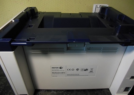
Ремонт МФУ Xerox WC 6015
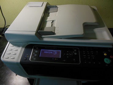
Сервисный центр Комплэйс выполняет Ремонт Xerox WC 6015
Замятие бумаги WC 6015
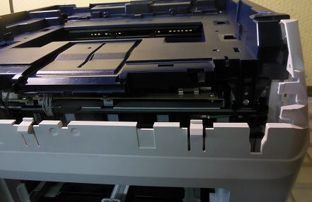
МФУ Xerox WC 6015 поступило в ремонт с постоянным сообщением о замятии бумаги, бумаги не было нигде.
После разборки аппарата подбираемся к датчику бумаги. Сам датчик прохождения бумаги находится сзади, показан стрелкой.

Сломанный датчик заменяем. На этом ремонт МФУ Xerox закончен.
Второй датчик находится в узле закрепления.
Треск при работе WC 6015
Треск в узле ксерографии
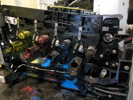
В другом МФУ Xerox WC 6015 при включении и работе раздавался сильный треск. Пришлось разбирать МФУ еще дальше.
Сильный треск был вызван тем, что в синем цвете забился тракт отвода отработанного тонера. После тщательной очистки спрессованного тонера, который превратился в камень, треск исчез. Отработанный тонер стал уходить в картридж.
Треск Xerox WC 6015 в области печки
Треск в области печки означает проскальзывание шестерней. В Xerox WC 6015 такое вероятно, если сломалось крепление печки. При такой неисправности шестерня печки не прижимаются к шестерне редуктора принтера. Поэтому и происходит проскальзывание и сильный треск.
Печка в этом МФУ с задней стороны крепится двумя винтами. А снизу печка цепляется за основание с помощью железных полукруглых упоров.
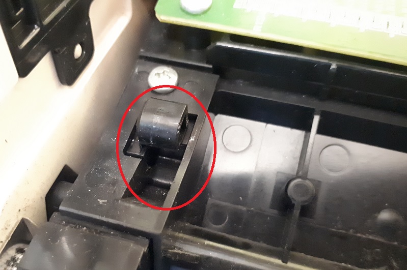
Если упор отсутствует печка не держится. В нашем случае полукруглый упор был отломан.
Ремонт выполнили следующим образом.
Стоимость ремонта крепления печки 3500 руб. Полукруг не обязателен.
Ошибка 024-360
Разберите по-новой весь принтер и проверьте разъемы на целостность и правильное соединение.Особенно тщательно проверьте контактные концы шлейфов. Если они повреждены, то отремонтируйте.
Ремонт контактной группы картриджей
Если у вас произошло повреждение контактной группы картриджа , то вряд ли найдете новую группу в продаже. Вообще для Xerox WC 6015 с запчастями проблема. Мы научились восстанавливать сломанные контакты. Но есть сложности — контактные группы никто не продает.
Для ремонта контакта нужно разобрать МФУ, вынуть контактную группу, починить сломанную контактную пластину.
Цена восстановления 2500 р.
Ошибка 092-651
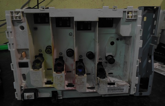
Ошибка 092-651 с разными подкодами возникает, когда аппарат не может выполнить калибровку цветов. Эта калибровка осуществляется при включении принтера. Принтер выполняет калибровку путем нанесения на ленту переноса прямоугольных образцов всех 4 цветов по-очереди. Затем считывает плотность этих образцов датчиками CTD. Если плотность печати любого из цветов недостаточна или не изменяется, то выдается ошибка 092-651 с соответствующим подкодом и МФУ блокируется .
Расшифровку подкодов найти не удалось. Особенностью ошибки 092-651 является то, что после этой ошибки принтер не закачивает тонер из картриджей в блок ксерографии и, похоже, простого выхода из этой ситуации нет.
Первая причина ошибки 092-651 — это загрязненные датчики CTD, расположенные сзади принтера под лентой переноса. CTD — Color Toner Density Sensor. Т.е. это датчики плотности тонера для цветовой калибровке в каждом цветном лазерном принтере. Расположены они сзади под лентой переноса. Для решения этой проблемы протираем датчики спиртом и запускаем МФУ снова.
Если проблема не решается, переходим к следующей процедуре.
Вторая причина — в блоке ксерографии недостаточно девелопера, который переносит тонер. Этот вариант происходит, если заправлять картридж не подходящим тонером. Например, универсальным тонером Samsung. В этом случае девелопер уходит и принтер печатает бледно. Чтобы добавить девелопер в блок ксерографии, нужно разобрать весь МФУ. Мало кто выполнить эту работу меньше, чем за 5000 руб.
Третья причина — в блоке ксерогафии мало тонера какого-то цвета. Причиной может быть неисправный картридж. В нашем случае была ошибка 092-651 код 2440000. Причиной являлись дешевые китайские картриджи, в которых выходное отверстие было заклеено липкой бумагой. После удаления бумаги клей остался. После установки картриджей клей плотно приклеился к уплотнительной резинке принтера. Это вызыИногда из-завает перекрытие выходного отверстия для тонера.
Решение такое. Во время включения вручную принудительно закачивать тонер каждого цвета, пока тонер не появится в блоке ксерографии. Когда он появится, принтер оживет и станет самостоятельно подкачивать тонер. Цена работы 2500 руб.
Подкоды ошибки 092-651
Иногда из-за плохого тонера возникает ошибка 092-651 28f0000. При таком коде при калибровке совсем отсутствуют цвета желтый, красный, синий. Есть только черный.
Решение. Замена тонера в цветных картриджах. С помощью сервисного меню можно отдельно запустить двигатели каждого картриджа. Но не более 3 секунд на каждый.
После этого все цвета появятся, но может возникнуть ошибка 092-651 2880000. Это совсем плохо. Скорее всего, код означает, что яркости черного не хватает для калибровки. Значит в блоке ксерографии плохой тонер или недостаточно девелопера. Но за заправку девелопером мы не беремся. Слишком много геморроя.
WC 6015 не печатает с компьютера
Очень типичная ситуация. При подключении Xerox WC 6015 к компьютеру с Windows 7 драйверы устанавливаются автоматически через обновления Windows. Далее пробуете что-нибудь напечатать и ничего не происходит — задания на печать уходят в никуда, даже ошибки не появляется.
Виной всему неправильный драйвер для Windows 7, а, возможно, и для Windows 8 и 10.
Решение: скачайте и установите драйвер с официального сайта Xerox (весит около 200Мб). После установки оригинального драйвера принтер Xerox WC 6015, который ранее не печатал от компьютера, стал печатать под Windows 7 и Windows 10.
Цены на ремонт WC 6015
Ремонт подачи бумаги (застревание) 2500-3000 руб.
Треск — ремонт узла ксерографии — от 3000 руб.
Ремонт контактной группы 2500 руб.
Ремонт крепления печки 3500 руб.
Ремонт WorkCentre 6015 начинается с разборки.
Разборка WC 6015
Сначала нужно снять сканер, для этого снимаем декоративную переднюю синюю крышку, которая крепится на защелках.
Затем снимаем боковую левую крышку.
Отсоединяем шлейфы и кабели, откручиваем спереди держатели лифта сканера, снимаем сканер вверх. Затем откручиваем сверху винты и снимаем верхнюю крышку.
Снимаем заднюю крышку принтера.
Снимаем правую боковую крышку с картриджами.
Следует отметить, что разборка Xerox WC 6015 — чрезвычайно трудоемкое дело. Спроектировано МФУ крайне неудачно для ремонта, требует большой концентрации, аккуратности и времени. За полную удачную разборку и сборку аппарата Xerox WC 6015 можно смело давать звание героя России.
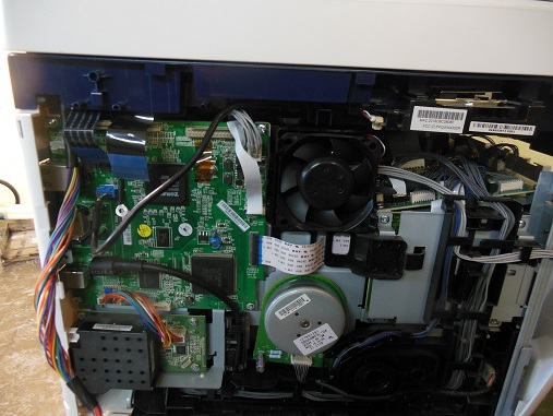
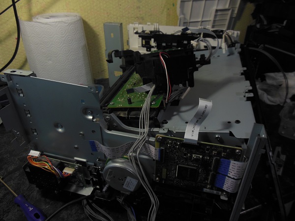
Наверху принтера расположены 3 платы.
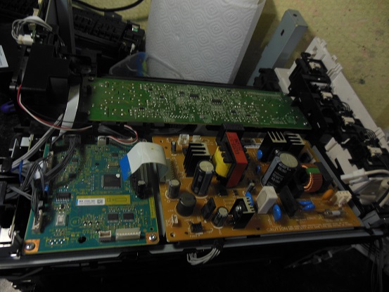
Чтобы добраться до узла ксерографии, нужно снять их все.
После этого нужно снять все боковые платы!, чтобы открутить 2 винта, крепящие верхнюю крышку сбоку.
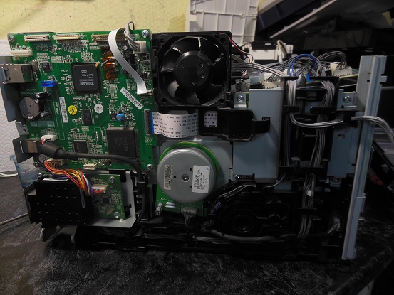
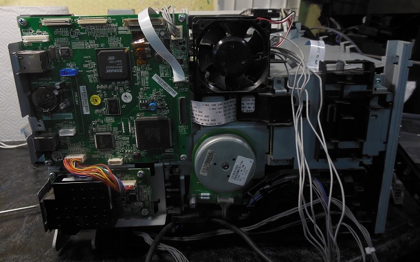
На последнем этапе снимаем плату MCU, за которой и находятся 2 винта.
Если после обратной сборки неправильно соединили какой-нибудь разъем, то при инициализации появится критическая ошибка 024-360. Диагностика тупая — разъем любой, но вероятнее всего шлейф.
Источник
Xerox 6015 ошибка 092 310 очистите датчик ctd
КОНФЕРЕНЦИЯ СТАРТКОПИ
Принтеры, копировальные аппараты, МФУ, факсы и другая офисная техника:
вопросы ремонта, обслуживания, заправки, выбора
Доброго дня!
Продолжение темы Xerox Phaser 6020: Ошибка 092-651 после заправки цветных картриджей.
Пока аппарат отложил в сторону. На днях приехал 6027 с аналогичной ошибкой. Наблюдал за датчиками во время инициализации, и у меня появился вопрос: датчик, который стоит слева, если смотреть на аппарат сзади (https://photos.app.goo.gl/aZEAvPTHgMQac7yd6) имеет видимое излучение красного цвета, которое изменяет свою интенсивность в процессе инициализации. Вот фото платы: https://photos.app.goo.gl/ciK6D9A3fY9K2QXN8
Второй же датчик, который стоит справа, значительно скромнее: https://photos.app.goo.gl/QKkXXK7W6ufmCUWR7, состоит всего из светодиода и фототранзистора: https://photos.app.goo.gl/AzEjiJcys7crTAV66
При этом, его излучения не видно. Так на обоих устройствах. Вопрос к знатокам и владельцам таких девайсов: правый датчик должен так работать? Или, может, с ним есть проблема?
(0)Правый так и должен работать. Я эти аппараты каждую неделю делаю, брак китайских картриджей поражает своим объемом.
(1) То есть причина этой ошибки именно в говнотонере?
(2)В последнее время столкнулся с тем, что сбоит накачка тонера, движок картридж вращает, а тонер с него не поступает. Х знает, как в столь простом механизме картриджа китайцы накосячили, но это носит массовый характер.
(3) Как понять по подкоду 2080000, какой из тонер-картриджей виноват?
И что делаете, чтоб тонер нормально подавался в блок проявки?
Источник
Чистка датчиков плотности цветных тонеров – Инструкция по эксплуатации Xerox Phaser 6000
Страница 56

Цветной принтер Phaser 6000/6010
Руководство пользователя
Чистка датчиков плотности
Датчики плотности цветных тонеров (Color Toner Density, CTD) измеряют оптическую
плотность тонера, отложившегося на маркировочном блоке при калибровке в процессе
печати. С каждой стороны маркировочного блока установлено по одному датчику. Это
обеспечивает одинаковую плотность тонера по всей длине ремня. Для достижения
оптимального качества печати принтер проверяет работу датчиков CTD в начале каждого
цикла калибровки. Датчики CTD следует чистить, когда происходит сбой датчика CTD, или
на панели управления появляется соответствующее сообщение, или Программа настройки
принтера выдает данное указание.
Если тонер попал на кожу или одежду, не удаляйте его тёплой водой или
чистящими растворителями. При использовании теплой воды тонер прилипнет —
тогда его будет трудно удалить. Если тонер попал на кожу или одежду, удалите его
щеткой, сдуйте его или смойте холодной водой с мылом.
Порядок чистки датчиков CTD:
1.
Выключите принтер и выньте вилку шнура питания из розетки.
Откройте заднюю крышку, нажав на фиксатор.
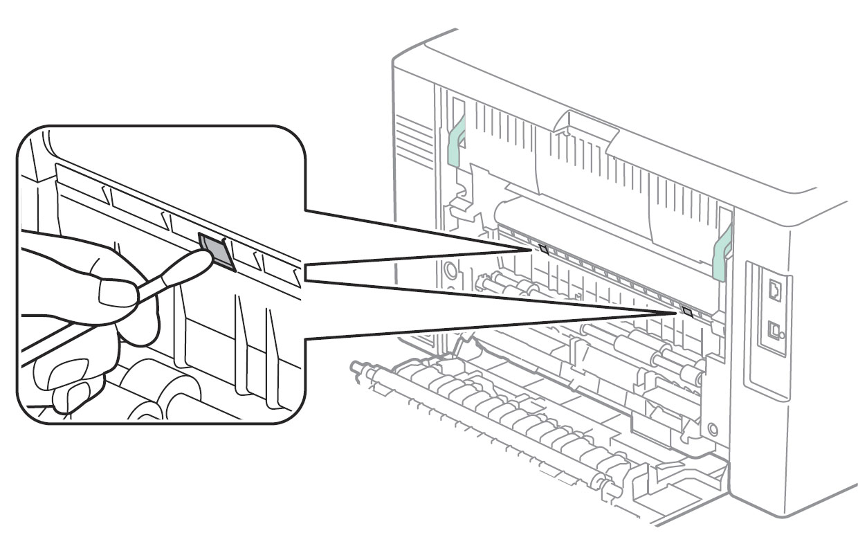
Очистите датчики CTD, протерев отверстия чистым сухим ватным валиком.
Не касайтесь помеченной наклейкой зоны на
нагревательном валу и вблизи него, во фьюзере. Можно получить ожог.
Источник
Xerox 6015 ошибка 092 310 очистите датчик ctd
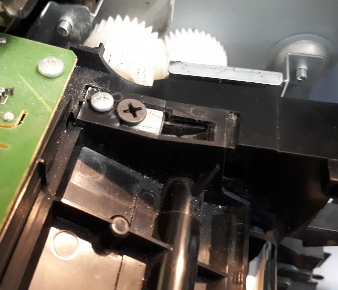
Этап № 3 Отделение блока ксерографии от основы аппарата.

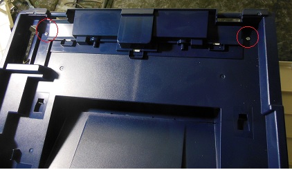
 На данном этапе разборки для снятия блока ксерографии необходимо открутить всего 4 шурупа, по два с каждой стороны. Шурупы находятся с задней стороны принтера и на фотографиях обведены красным. Внимание!! Обратите внимание на посадку блока ксерографии.

 Прежде, чем извлечь блок ксерографии, необходимо извлечь провода из проложенной трассы. Это достаточно неудобная процедура и в плане извлечения, и в плане последующей укладки (наберитесь терпения и дышите глубже, как говорится).

Извлечение блока ксерографии
 Все, больше блок ксерографии ничего не удерживает, и его можно извлечь. Для этого его достаточно просто поднять вверх. Внимание!! Перед последующей установкой блока ксерографии рекомендуем полностью очистить основу аппарата от пыли и тонера. Также не лишним будет почистить ролики захвата и отделения бумаги средством для восстановления резиновых поверхностей средством Platenclene.

Извлеченный блок ксерографии xerox 6010/6015

Вот такое количество шурупов и болтов пришлось открутить, чтобы извлечь блок ксерографии
Удивительно, как много деталей нужно снять для того, чтобы извлечь блок ксерографии! Кстати, оригинальное название данного блока Xero deve LPH belt assy (xerographics assembly)
Внимание!! Блок не имеет парт- номера т.е. как запчасть отдельно не поставляется. Это значит, что если аппарат на гарантии и блок ксерографии вышел из строя, то корпорация Xerox просто подарит вам новый аппарат.
Оцените качество заметки
97 комментариев
Офигеть. вот это да. Вот это работа. Спасибо большое за такой обзор. Осталось узнать, как же можно сам девелопер поменять в блоке. )) Ужас принтер.
WC 3045 с таким же гемором разбирается.
А зачем блок ксерографии снимали?
Корпус снимается так же муторно (разбор одинаков на 95%), но вот редуктор намного проще, да и сам блок ксерографии содержит на порядок меньше деталей. Хотя при первом разборе на выходе получил ошибку светодиодной линейки, к счастью светодиодная линейка и шлейф от Xerox 6000 подошли.
Вы автор этой статьи про разбор Xerox WorkCentre 6015 ? Подскажите пожалуйста название детали. Контакты которые считывают чипы у картриджей как они называются эти контакты, или вся полностью деталь? у меня сломался такой контакт, где можно найти такую деталь?
Это контактная группа чипа, деталь можно достать исключительно с другого аппарата. Ищите писанные аппараты и снимайте оттуда или обращайтесь в сервис
есть такой принтер. сбросьте фото нужной детали neptun-bo@yandex.ru
Сорри, первую часть упустил
ох, помню я этот аппарат, частенько в ремонт приходит.
Один такой разбирал, чтобы вычистить ксерографию, потом так и не завёлся, с ошибкой по плате MCU.
Огромное спасибо за статью! С вашей помощью я сэкономил много сил и времени!
ошибка 124-333 Xerox WC 6015.после разборки выскочила ошибка. ткните носом где смотреть.какой разъем на какой плате. Спасибо.буду рад любой помощи.
Поклон в пояс таким людям как автор.
Большое спасибо за статью. Только у меня после обратной сборки пропал розовый цвет. С одной стороны проявляется немного пятнами. Снимал блок проявки розовый, светодиодную линейку. Три раза уже перебрал, но толку мало. Если есть мысли, помогите.
Не попадает напряжение на магнитный вал или фотовал. Где-то прервалась цепочка
После переборки блока “Drive Assy Deve” Xerox WC 6015 (падал в ошибку 042-372 при печати монохромом), выскочила следующая ошибка: 124-333. Подскажите пожалуйста, на что он ругается. Заранее при много благодарен!))
В редукторе есть большой черный пластиковый блок с шестеренками и датчиком, этот блок отвечает за переключение режимов монохромного и цветного. В этот блок попал тонер и его клинит и датчик не фиксирует режим переключения режимов, что приводит к появлению ошибки. Необходимо очистить шестерни этого блока от грязи и заново смазать
Именно этот блок чистил и смазывал. Так как была ошибка при печати чёрным и слышен был хруст говоривший о клине муфты… А теперь номер ошибки другой. По мануалу вроде как ругается на разъемы P1 и P23. Прозвонил, всё в порядке. Вы не подумайте. Я не сомневаюсь в Вас, хочется понять в чём разница между ошибкой 042-372 и 124-333. Я практикующий мастер и у меня на обслуживании ещё 5 таких аппаратов, рано или поздно в них лезть, а этот аппарат новый и не отработан. Спасибо за понимание и помощь!)))
Невнимательно прочитал Ваш пост, ошибка 124-333. указывает на неисправность ■ LED
Driver Board, PL7.1.5
■ LED/MCU Cable, PL7.1.6
■ MCU Board, PL7.2.2
Проверьте, может один из четырех кабелей неверно зафиксировали?
Теперь в этом филиале окажусь почти через месяц. Но хочется подготовиться. LED Driver Board это ведь панель управления с кнопками управления и дисплеем? Почему-то я так решил со своим кривым знанием английского изучая мануал. Так вот, я снял панель управления для прозвонки, и увидел, что шлейф там всего один с маркировкой на плате “P1”. Всё звонилось, но увидел микротрещины на дорожках. Предположил, что возможны потери из-за повышенного сопротивления и зачистив дорожки чуть выше края, обрезал места с трещинами, в общем стандартная процедура. Но это не помогло. И по поводу четырёх кабелей. Там, как я уже сказал, один шлейф панели управления, второй шлейф линейки сканера, третья проводная-шина насколько я помню полностью относится к сканеру и четвертая это одиночный провод – земля. Перепутать там невозможно. Или это не те четыре кабеля о которых Вы говорите?
То о чем вы говорите, это LCD дисплей,а я говорю о LED. В данном случае имеются в виду светодиодные линейки расположенные в блоке ксерографии. Всего их четыре по одному на каждый цвет, поэтому и четыре шлейфа.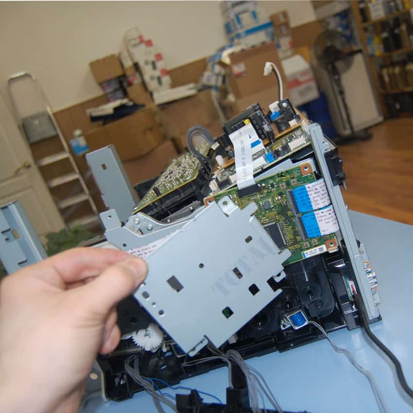
Стыдоба… Теперь понял о чём речь. На другом аппарате чистил синий блок. Спасибо, в конце месяца, как доеду до филиала, отпишусь. Большой опыт работы с Kyocera’ми, пишите на почту, если возникнут сложности, постараюсь помочь.
Здравствуйте! В общем добрался до филиала. Раскидал аппарат, все 4 шлейфа блоков были подключены надёжно. Но… Присмотревшись к контактам через лупу, я увидел металлическую стружку толщиной с волос и длиной в 2 мм. которая замыкала 2 контакта одного из разъёмов. Ума не приложу откуда она там взялась. В общем ваша подсказка мне очень помогла. Спасибо Вам огромное!
Xerox 6000 поменял девелопер теперь не заводится. Включается жужжит но на табло не загорается ни одна кнопка
Начните с правильности подключения разъемов
Здравствуйте! у нас проблема с Xerox WC6015, при сканировании и копировании выдает отпечатки синего фона, с компьютера распечатывает корректно. Можете подсказать в чем проблема?
Если сканируете с автоподатчика, то с правой стороны есть узкое стеклышко, протрите его спиртосодержащей жидкостью.
в этой модели нет автоподатчика.. он полностью все изображение синим выдает после сканирования или копирования
Тогда начните с того, что вытащите и заново вставьте шлейф сканера на плате форматора и сканирующей линейки. Если не поможет, то возможно проблема в сканирующей линейке (или грязь попала или брак). Тут в любом случае необходима помощь специалиста.
Здравствуйте! Блок питания будет выдавать напряжения с отключенными платами ? И какие напряжения должны присутствовать?
Так глубоко аппарат не ковырял
А “закройте заднюю дверцу 077-304 как лечится?
Сзади принтера с правой стороны есть блок с оптическими датчиками, возможно туда попала грязь, часто слетает пружинка с флажка датчика.
Здравствуйте! Хотел высказать свою благодарность за подробную информацию! Все получилось! Спасибо.
Уточнение: “Отсоедините верхнюю часть корпуса. Для этого открутите четыре фиксирующих шурупа и извлеките его, потянув вверх.” Пр факту их 6 (2 со стороны задней крышки).
На данном этапе все понятно с разборкой корпуса Xerox WC 6000-6015, а дальше? Поступил аппарат (Xerox WC 6015)с явным треском (при инициализации и печати) справа внизу (сторона картриджей), явно механика, но вот где искать причину и как туда добраться с наименьшими потерями мне не известно. Такой монстр у меня впервые в отличии от его монохромных братьев. Если есть возможность, подскажите куда копать. Спасибо.
Нашел ваше продолжение второй части и на другом форуме такой комментарий (Если трещит, но при этом работает(выдает копию иль печатает), то похоже заклинило шнек отвода отработки на одном из цветов.) схожий с моей проблемой, буду искать, извините за беспокойство.
Причина найдена: заклинило шнеки закоксовавшимся тонером в местах подачи тонера из картриджа в аппарат (те что с подпружиненными пятаками) на местах черного и синего картриджей.
Валерий,а как лечилось? Поподробней нельзя?
И спасибо Вам за подробную инструкцию по разборке Xerox WC 6015!
Принтер выдал сообщение “092-651 код 2110000” при включении и предлагает перезагрузить его. В чем может быть дело и как от этого избавиться? Нашел информацию об очистке датчика CTD, почистил. Но принтер после включения ругнулся на черный картридж. Поменял картридж и снова сообщение “092-651 код 2110000”
Подскажите пожалуйста, Xerox WC 6015 не включается вообще.При нажатии клавиши включения, щелчок реле и ни чего не происходит. На что обратить внимание?
Скорее всего плата main board приказала долго жить, для аппарата приговор.
Добрый день.
Помогите с заменой контактов чипа картриджа (контактная группа) в Москве. Может у кого завалялся?
Job707@list.ru
Добрый день! Разбирал по Вашему обзору Xerox Phaser 6000, очень помогло. Собрал, неделю печатал нормально. Потом перестал захватывать второй лист. Сейчас захватывает только первый лист и то если лежит один. Подкладываю второй, уже не берёт.Даже нет работы на захват и подачу бумаги. Ошибку выдаёт, нет бумаги. В чём может быть причина или причины. Заранее Спасибо!
Судя по описанию, ослабла пружина довода муфты захвата бумаги. Муфта выглядит как шестерня посаженная на ось захвата бумаги. Эту шестерню доводит пружина, попробуйте откусить несколько усиков, а лучше найти более жесткую пружину. Так же обратите внимание на язычек электромагнита, он не деформирован?
Про муфту понятно , найду. Я не специалист, а где находится электромагнит и как он выглядит? Спасибо!
Спасибо за Ваши советы и помощь!
А сам блок проявки как снять? Уже всю голову сломал. Руки опускаются.
Добрый день.
Долгие годы аппарат Xerox 6015NI не доставлял никаких проблем. Но недавно на внутренней стороне стекла сканера появился налёт и теперь на сканах тёмное кривое пятно в конце сканирования. Трудно ли добраться дотуда, чтобы почистить внутреннюю поверхность стекла? Что надо сделать?
Главное отделить сканер от принтерной части.
Для этого отделяется передний кожух аппарата, далее снимаем левый кожух, видим шлейфы и провода идущие на блок сканера, и аккуратно отделяем не забыв сфотографировать расположение проводов и разъемов. Внимание. Широкий шлейф с тонкими дорожками вытаскиваем без РАСКАЧКИ, контакты сидят в микропазах. которые можно повредить. Отделяем два подпружиненных кронштейна и плавно снимаем блок сканера. Отделяем внимательно не оторвав шлейфы. При обратной сборке криво воткнутый широкий шлейф выводит блок электроники из строя, будьте внимательны.
После отделения сканера его разборка не должна вызвать вопросов, так как там все предельно просто. Ах да чуть не забыл, нужно в блоке сканера отщелкнуть панель управления, так как под ней есть скрытые шурупы удерживающие стекло. Писанины много, а делов на пол часа. Если опыта работы с оргтехникой нет, лучше отдайте в сервис.
Здравствуйте добрался до блока ксерографии xerox wc 6015 и увидел такую вещь:
https://preview.ibb.co/h6FrQJ/IMG_20180617_193144.jpg
То есть пленка на вале порвалась до такого состояния(об крепление посередине)
Это термопленка? Просто вытащить вал, на него новую пленку и собрать?
Это лента переноса. Без нее в принципе нанесение изображения невозможно. На складе валяется с бу аппарата. Если действительно хотите починить, то могу бесплатно дать. Самовывоз в Москве или за Ваш счет вывоз транспортной компанией.
Действительно хочу починить. А тем более совсем не против получить бесплатно :). Живу не в Москве, готов оплатить транспортную компанию. Как можно связаться?
ПИШИТЕ НА ПОЧТУ, КОНТАКТЫ ВВЕРХУ САЙТА.
Здравствуйте. Разбирал МФУ и сломал разъем на сканер(верхний левый на Вашем фото, который поменьше).Подскажите пожалуйста его название? FPC, FFС, cколько pin(я насчитал 16) и если знаете, то где купить. Спасибо заранее.
Здравствуйте! Разбирал аппарат по причине ошибки “Замятие бумаги на выходе”. До этого несколько раз бумага то застревала то полностью сминалась в гармошку на выходе. При вытаскивании остались кусочки, пылесос их не вытягивал, пришлось разобрать. Разобрал, кусочки вытащил. Не собирая подключил вернюю часть (сканер) чтобы проверить. Всё работало, застреваний не было. Собрал все обратно, включил и вместо печати чистые листы (чёрный или цвет – без разницы). Ошибки никакой нет, на плёнке следов тонера нет, картриджи почти полные. Опять разобрал, все шлейфы и провода подключены, вроде бы ничего не перебито. Подскажите, что могло случиться?
Слева на крышке есть пружинный контакт на трансфер, он из паза не выскочил?
Не совсем понимаю о какой крышке и о каком контакте идёт речь. Это есть на Ваших фото?
Контакт идущий на трансфер-ролик позади принтера, он выглядит как черная пористая цилиндрическая деталь. крепящаяся на откидывающуюся крышку
Здравствуйте. Не совсем по теме. т.к. проблема с технически аналогичным аппаратом, Dell 1355cnw.Без каких либо явных причин принтер впал в “кому” с ошибкой 009-654 2880000, включите заново и если не поможет, то в сервис.
Принтер инициализируется как положено, жужжит и гремит как обычно, но с ошибкой в конце. Компьютер принтер видит. При входе в сервисное меню, все тестируется ок, при инициализации любой функции связанной с печатью пишет выполняю и зависает.
Почитав форумы, почистил CTD сенсор, не помогло.Подумав, что возможен дефект пайки с годами, разобрал и пропаял элементы CTD и MOB сенсоров.После сборки проходит инициализацию и ругается на CTD unit. До моего вмешательства были тестовые цветные прямоугольники напротив CTD сенсора. Сейчас немного равномерно сыпет тонером на плёнке переноса (цветная пыль) и в момент когда должны появится цветные прямоугольники, появляется 3 тонкие цветные полоски во всю ширину плёнки переноса, как будто просыпалось чуть больше тонера. Разобрал и собрал пару раз, не помогло. ) Обнулил NVRAM. Перепрошил с компа. Может подкинете идею куда глянуть? Интересно, что за оригинальная проблема была и могла ли она просто перерасти в большую. Например какой либо чип умер совсем. Сам принтер уже не очень нужен, но хочется дойти до истины. 🙂
Спасибо.
Источник
You are here: Home / error code / Xerox Phaser 7100 error and solving error codes
– Compatible Printer model: Xerox Phaser 7100
– Xerox Phaser 7100 Error Codes with quick guides:
- Code: 010-105, 010-112
- Description: Fuser Unit Exit Sensor Jam The Fuser Unit has failed due to one of the following problems. • After a paper that had stopped at the Registration position was transported again, the paper did not reach the Fuser Exit Sensor within the specified time. • After the Fuser Exit Sensor has detected a paper, the paper passed by the Fuser Exit Sensor before the specified time. • 010-105: Fuser Unit Exit Sensor On Jam • 010-112: Fuser Unit Exit Out Early Jam
- Causes: • Fuser Motor (Fuser Drive Assembly), PL 4.2.16 • 2nd BTR (Transfer Roller), PL 4.3.18 • Registration Sensor, PL 5.1.3 • Registration Roller (Registration Chute Assembly), PL 5.1.1 • Registration Clutch, PL 5.1.11 • Exit Roller (Fuser Unit), PL 10.1.1 • Fuser Exit Sensor (Fuser Unit), PL 10.1.1 • Paper Handling Motor (Paper Handling Drive Assembly, PL 11.1.19 • MCU PWB, PL 12.1.15
- Troubleshooting Guides: 1. Check the paper transport path Is there any debris on the paper transport path? Remove the debris. Go to step 2. 2. Check the installation of the Registration Roller (Registration Chute). Is the Registration Chute installed properly? Go to step 3. Reinstall the Registration Chute. 3. Check the Registration Roller (Registration Chute). Is the Registration Chute damaged? Replace the Registration Chute. Go to step 4. 4. Check the Registration Sensor operation. Perform DC330 Component Control [071-102] to check the operation of the Registration Sensor. Is the Registration Sensor operating properly? Go to step 5. Go to Sensor Troubleshooting. 5. Check the Registration Clutch operation. Perform DC330 Component Control [071-013] to check the operation of the Registration Clutch. Is the Registration Clutch operating properly? Go to step 6. Go to Registration Clutch. 6. Check the Paper Handling (P/H) Motor operation. Perform DC330 Component Control [071-009] to check the operation of the P/H Motor. Is the P/H Motor operating properly? Go to step 7. Go to Paper Handling Motor. 7. Check the Fuser Exit Sensor operation. Perform DC330 Component Control [071-104] to check the operation of the Fuser Exit Sensor. Is the Fuser Exit Sensor operating properly? Go to step 8. Go to Fuser Exit Sensor. 8. Check the Fuser Motor operation. Perform DC330 Component Control [010-001] to check the operation of the Fuser Motor. Is the Fuser Motor operating properly? Replace the MCU PWB. Go to Fuser Motor.
- Code: 010-106
- Description: Exit Off Jam After a paper has passed by the Registration Sensor, the paper did not pass by the Fuser Exit Sensor within the specified time.
- Causes: • Fuser Motor (Fuser Drive Assembly), PL 4.2.16 • Fuser Exit Sensor (Fuser Unit), PL 10.1.1 • Exit Roller (Fuser Unit), PL 10.1.1 • MCU PWB, PL 12.1.15
- Troubleshooting Guides: 1. Check the paper transport path Is there any debris on the paper transport path? Remove the debris. Go to step 2. 2. Check the Fuser Unit. Is the Fuser Unit damaged? Go to step 3. Reinstall the Fuser Unit. 3. Check the Fuser Exit Sensor operation. Perform DC330 Component Control [071-104] to check the operation of the Fuser Exit Sensor. Is the Fuser Exit Sensor operating properly? Go to step 4. Go to Fuser Exit Sensor. 4. Check the Fuser Motor operation. Perform DC330 Component Control [010-001] to check the operation of the Fuser Motor. Is the Fuser Motor operating properly? Replace the MCU PWB. Go to Fuser Motor.
- Code: 010-311 … 010-355
- Description: • 010-311: Fuser Unit Heat Roll STS-1 Disconnection Fail • 010-319: Fuser Unit NC Sensor Differential Amp Fail • 010-328: Fuser Unit Warm Up Time Fail (Not Ready) • 010-331: Heat Roll STS Over Temperature Fail • 010-332: Heat Roll NC Sensor Disconnection Fail • 010-333: Heat Roll NC Sensor Over Temperature Fail • 010-334: Heat Roll NC Sensor Broken Fail • 010-335: Heat Roll NC Sensor Range Fail • 010-338: Fuser Unit On Time Fail • 010-339: Heat Roll NC Sensor Low Temperature Fail • 010-340: Fuser Unit Detached • 010-344: Heat Roll STS Sensor Low Temperature Fail • 010-345: Fuser Unit Hard Relay Off Fail • 010-346: Fuser Main Lamp Data Renewal Fail • 010-347: Fuser Sub Lamp Data Renewal Fail • 010-355: Fuser Cool Down Timeout Fail.
Fuser Unit Fail The Fuser Unit has failed due to one of the following problems. • A differential circuit output error was detected between the detection output and the compensation output of the Fuser Unit NC Sensor. • When the Lamp On time meets the following conditions, where Tws °C is the temperature at the Wait state start time that is obtained at the NCSCenter. • The temperature monitor AD value of the STS-Front was detected to be higher than T[HITMP (2)] 3 times in a row. • During Warm Up Control, an abnormal detected temperature due to NC Sensor malfunction or poor contact was detected. • The Fuser Unit Main Lamp or Sub Lamp has been On continuously for longer than the setting time (NVM). • At the first Lamp Off after it was turned On, the NC temperature is continuously at EP_U4_LOW_NC °C or lower 8 or more times in a row. • The Thermistor disconnection detected. • At the first Heater OFF after it was turned On, the detected temperature at the edge STS is continuously at EP_U4_LOW_STS °C or lower 8 or more times in a row. • Notified at the moment the Relay is cut off from the circuit. • The detected temperature at the NC or the STS has not changed during this period, although the Main Lamp has been On continuously for 15 s or longer. • The Cool Down Mode has continued for EP_U4_COOL_TIME * 10 s or longer. - Causes: • DRW Fuser Harness Assembly, PL 4.1.7 • Fuser Unit, PL 10.1.1 • MCU PWB, PL 12.1.15 • AC PWB Assembly, PL 12.1.16 • LVPS PWB, PL 12.2.1 • Option Harness Assembly, PL 12.3.5
- Troubleshooting Guides: 1. Check the installation of the Fuser Unit. Is the Drawer Connector between the Fuser Unit and Main Unit (P/J601) free of broken/bent pins, debris, burns, and etc., and the unit is installed properly? Go to step 2. Reinstall the Fuser Unit. 2. Check the connections between the Fuser Unit and MCU PWB, as well as between the Fuser Unit and AC PWB. Are the connectors P/J601, P/J459, and P/J503 connected securely? Go to step 3. Connect the connectors P/J601, P/J459, and P/J503. 3. Check the connection between the AC PWB and MCU PWB. Are the connectors P/J505 and P/J464 connected securely? Go to step 4. Connect the connectors P/J505 and P/J464. 4. Check the conductivity of the DRW Fuser Harness Assembly. Are the connections between P/J601<=> P/J459 and between P/J601 <=> P/J503 conducting properly? Go to step 5. Replace the DRW Fuser Harness Assembly. 5. Check the conductivity of the Option Harness Assembly. Is the connection between P/J505 <=> P/J464 conducting properly? Go to step 6. Replace the Option Harness Assembly. 6. Check the voltage supply (+5VDC) to the Fuser Unit. Measure the voltages between the MCU PWB GND <=> P/J459-5 and MCU PWB GND <=> P/J459-13. Is there a voltage (approx. +5VDC) output? Go to step 7. Go to +5VDC Power Troubleshooting. 7. Check the voltage supply (+3.3VDC) to the Fuser Unit. Measure the voltage between the MCU PWB GND <=> P/J459-1. Is there a voltage (approx. +3.3VDC) output? Go to step 8. Go to +3.3VDC Power Troubleshooting. 8. Replace the Fuser Unit. Does the error persist? Go to step 9. Troubleshooting complete. 9. Replace the AC PWB. Does the error persist? Replace the MCU PWB. Troubleshooting complete.
- Code: 010-330
- Description: Fuser Motor Fail The Fuser Motor rotation failure was detected.
- Causes: • Front Harness Assembly, PL 4.2.11 • Fuser Motor (Fuser Drive Assembly), PL 4.2.16 • MCU PWB, PL 12.1.15 • LVPS PWB, PL 12.2.1 • Main Harness Assembly, PL 12.3.1
- Troubleshooting Guides: 1. Check the Fuser Motor operation. Perform DC330 Component Control [010-001] to check the operation of the Fuser Motor. Is the Fuser Motor operating properly? Replace the MCU PWB. Go to step 2. 2. Check the installation of the Fuser Motor. Manually rotate the Fuser Motor. Does the Motor rotate? Reinstall the Fuser Drive Assembly. Go to step 3. 3. Check the connections between the Fuser Motor and MCU PWB, as well as between the Fuser Motor and LVPS PWB. Are the connectors P/J475, P/J4751, P/J4755, P/J524, P/J2711, and P/J242 connected securely? Go to step 4. Connect the connectors P/J475, P/J4751, P/J4755, P/J524, P/J2711, and P/J242. 4. Check the conductivity between the Fuser Motor and Relay Connector. Are the connections between P/J4755 <=> P/J4751 and between P/J242 <=> P/J2711 conducting properly? Go to step 5. Replace the Front Harness Assembly. 5. Check the conductivity between the Relay Connector and LVPS PWB. Is the connection between P/J2711 <=> P/J524 conducting properly? Go to step 6. Replace the Main Harness Assembly. 6. Check the conductivity between the Relay Connector and MCU PWB. Is the connection between P/J4751 <=> P/J475 conducting properly? Go to step 7. Replace the Main Harness Assembly. 7. Check the voltage supply (+3.3VDC) to the Fuser Motor. Measure the voltage between the MCU PWB GND <=> P/J475-16. Is there a voltage (approx. +3.3VDC) output? Go to step 8. Go to +3.3VDC Power Troubleshooting. 8. Check the voltage supply (+24VDC) to the Fuser Motor. Measure the voltage between the LVPS PWB GND <=> P/J524-1. Is there a voltage (approx. +24VDC) output? Close the Interlock Switch and check. Replace the Fuser Drive Assembly. Replace the LVPS PWB.
- Code: 010-421, 010-906
- Description: Fuser Unit Error – Life End The print volume has reached the specified value (Max value), which indicates that further usage will damage the Fuser Unit. • 010-421: Fuser Unit Life End Quality (operation can still continue) (quality lifespan has ended) (ERU) • 010-906: Fuser Unit Life End
- Causes: • Fuser Unit, PL 10.1.1
- Troubleshooting Guides: 1. Replace the Fuser Unit. 2. Perform DC135 HFSI to reset the following life counters: • Chain-Link 950-880: Fuser Unit PV • Chain-Link 950-884: Fuser Unit Heat Time
- Code: 016-322
- Description: JBA Accounting Data Full The cumulated accounting data reached the specified value (15,000).
- Causes:
- Troubleshooting Guides: 1. After an external Accounting Server has read the accounting data, turn the power Off and On. 2. If the problem persists, refer to Common System Fail“.
- Code: 016-328
- Description: Cont-MCU Cable Connection Fail The controller has detected a failure at its cable connection with the MCU PWB.
- Causes: • MCU PWB, PL 12.1.15 • I/P PWB, PL 12.4.1
- Troubleshooting Guides: 1. Check the connection of the cable between the I/P PWB and MCU PWB. 2. Replace the defective cable.
- Code: 016-336
- Description: Cont Program ROM Fail-2 Write command failure of Program ROM 1.
- Causes: • I/P PWB, PL 12.4.1 • 1 GB DDR2 DIMM, PL 12.4.2
- Troubleshooting Guides: 1. Remove and reinstall the I/P PWB ROM DIMM #1). 2. Replace the I/P PWB ROM DIMM #1). 3. Replace the I/P PWB PWB).
- Code: 016-350
- Description: Cont SEEP-ROM Diagnostic Fail-1 Unable to obtain the Product ID.
- Causes: • I/P PWB, PL 12.4.1
- Troubleshooting Guides: 1. Check the SEEP ROM contacts (for bent and broken pins, etc.). 2. Replace the I/P PWB PWB).
- Code: 016-351
- Description: Cont SEEP-ROM Diagnostic Fail-2 Error has occurred at W/R/V Test.
- Causes: • I/P PWB, PL 12.4.1
- Troubleshooting Guides: 1. Check the SEEP ROM contacts (for bent and broken pins, etc.). 2. Replace the I/P PWB PWB).
- Code: 016-365
- Description: Cont USB2.0 Device Fail Error has occurred at W/R/V Test of PCI Config Space or at W/R/V Test of internal registers.
- Causes: • I/P PWB, PL 12.4.1
- Troubleshooting Guides: 1. Remove and reseat all connectors on the I/P PWB. 2. If problem persists, replace the I/P PWB PWB).
- Code: 016-372 … 016-382
- Description: • 016-372: Cont HDD FileSystem Fail-A • 016-373: Cont HDD FileSystem Fail-B • 016-374: Cont HDD FileSystem Fail-C • 016-375: Cont HDD FileSystem Fail-D • 016-376: Cont HDD FileSystem Fail-E • 016-377: Cont HDD FileSystem Fail-F • 016-378: Cont HDD FileSystem Fail-G • 016-379: Cont HDD FileSystem Fail-H • 016-380: Cont HDD FileSystem Fail-I • 016-381: Cont HDD FileSystem Fail-J • 016-382: Cont HDD FileSystem Fail-P The HDD has failed due to one of the following problems. • The Boot Diag has detected an HDD logical error (partition A). • The Boot Diag has detected an HDD logical error (partition B). • The Boot Diag has detected an HDD logical error (partition C). • The Boot Diag has detected an HDD logical error (partition D). • The Boot Diag has detected an HDD logical error (partition E). • The Boot Diag has detected an HDD logical error (partition F). • The Boot Diag has detected an HDD logical error (partition G). • The Boot Diag has detected an HDD logical error (partition H). • The Boot Diag has detected an HDD logical error (partition I). • The Boot Diag has detected an HDD logical error (partition J). • The Boot Diag has detected an HDD logical error (partition P).
- Causes: • HDD Productivity Kit, PL 12.4.20
- Troubleshooting Guides: 1. Initialize the HDD (refer to DC355 Hard Disk Diag).

Solve Xerox Phaser 7100 Error codes
- Code: 024-900
- Description: Tray 1/ 2/ 3 Of Place Paper cannot be fed (paper path not available) as an upper Tray compared of the selected Paper Supply Tray is in [Removed] state. This fault occurs depending on the paper transport configuration of the engine.
- Causes: • Tray 1 Paper Size Switch, PL 2.1.6 • Tray Assembly 250, PL 2.1.11 • Tray Assembly 550, PL 15.1.1 • Tray 2/3/4 Paper Size Switch, PL 15.1.5
- Troubleshooting Guides: 1. Check to make sure all trays above the tray in use are properly installed. If it is check the Paper Size Switch in DC330 Component Control. If it works replace the Tray. If it doesn’t work, replace the Paper Size Switch. • Tray 1 Paper Size Switch • Tray 2/3/4 Paper Size Switch
- Code: 024-910
- Description: Tray 1 Error: Size Unknown When the paper length in Slow Scan direction is measured on the paper feed path, the detected size is different from the size detected by the Tray.
- Causes: • Paper Size Switch, PL 2.1.6 • MCU PWB, PL 12.1.15 • Main Harness Assembly, PL 12.3.1
- Troubleshooting Guides: 1. Check the installation of the Tray. Is the Tray installed properly? Go to step 2. Install the Tray. 2. Check the paper Guide. Is the paper Guide in the Tray set correctly? Go to step 3. Set the paper Guide. 3. Check the Paper Size Switch operation. Perform DC330 Component Control to check the On/ Off operation of each Switch of the Paper Size Switch. • Switch 0 [071-106] • Switch 1 [071-107] • Switch 2 [071-108] • Switch 3 [071-109] Are the Switches working properly? Replace the MCU PWB. Go to step 4. 4. Check the connection between the Paper Size Switch and MCU PWB. Are the connectors P/J4653A and P/J465A connected securely? Go to step 5. Connect the connectors P/J4653A and P/J465A. 5. Check the conductivity between the Paper Size Switch and MCU PWB. Is the connection between P/J4653A <=> P/J465A conducting properly? Replace the Paper Size Switch. Replace the Main Harness Assembly.
- Code: 024-923 … 024-925
- Description: (Y/ M/ C) Toner Cartridge Error: Life End Toner (Y/ M/ C/ K) error has occurred due to one of the following problems. • Printing cannot be continued during color printing because (Y/ M/ C) toner has run out. Or, color printing was specified when printing cannot be continued because (Y/ M/ C) toner has run out. • Toner K is Empty and any of the Toner YMC is also Empty. • 024-923: Operation Y Toner Empty • 024-924: Operation M Toner Empty • 024-925: Operation C Toner Empty
- Causes: • Toner Cartridge (Y/ M/ C), PL 8.1.1 – PL 8.1.3
- Troubleshooting Guides: 1. Replace the Toner Cartridge (Y/ M/ C)).
- Code: 024-933, 024-940, 024-941
- Description: (Y/ M/ C) Imaging Unit Cartridge Error: Life End Imaging Unit error has occurred due to one of the following problems. • During color printing, it was detected that printing cannot be continued because of (Y/ M/ C) Imaging Unit Life End. • Or, color printing was specified when printing cannot be continued because of (Y/ M/ C) Imaging Unit Life End. • 024-933: Operation Y Imaging Unit End of Life • 024-940: Operation M Imaging Unit End of Life • 024-941: Operation C Imaging Unit End of Life
- Causes: • Imaging Unit (Y/ M/ C), PL 6.1.1
- Troubleshooting Guides: 1. Replace the Imaging Unit (Y/ M/ C)).
- Code: 024-946 … 024-949
- Description: Tray (1/ 2/ 3/ 4) Out of Place The system detected that Tray 1/ 2/ 3/ 4 was not installed. • 024-946: Tray 1 Out Of Place • 024-947: Tray 2 Out Of Place • 024-948: Tray 3 Out Of Place • 024-949: Tray 4 Out Of Place
- Causes: • Tray 1 Paper Size Switch, PL 2.1.6 • Tray Assembly 250, PL 2.1.11 • Tray Assembly 550, PL 15.1.1 • Tray 2/3/4 Paper Size Switch, PL 15.1.5
- Troubleshooting Guides: 1. Reseat the Tray. If the Tray is seated properly, check the Paper Size Switch in DC330 Component Control. If it works, replace the Tray. If it doesn’t work, replace the Paper Size Switch. • Tray 1 Paper Size Switch • Tray 2/3/4 Paper Size Switch
- Code: 024-950
- Description: Tray 1 Error: Paper Empty The system detected that Tray 1 has no paper.
- Causes: • No Paper Sensor 250, PL 2.2.2 • Feeder Harness Assembly, PL 2.2.3 • MCU PWB, PL 12.1.5 • Main Harness Assembly, PL 12.3.1
- Troubleshooting Guides: 1. Check the paper in the Tray. Is the paper in the Tray loaded correctly? Go to step 2. Load the paper. 2. Check the No Paper Sensor 250 operation. Perform DC330 Component Control [071-101] to check the operation of the No Paper Sensor 250. Is the Sensor working properly? Replace the MCU PWB. Go to step 3. 3. Check the connection between the No Paper Sensor 250 and MCU PWB. Are the connectors P/J4652A, P/J4651A, and P/J465A connected securely? Go to step 4. Connect the connectors P/J4652A, P/J4651A, and P/J465A. 4. Check the conductivity between the No Paper Sensor 250 and Relay Connector. Is the connection between P/J4652A <=> P/J4651A conducting properly? Go to step 5. Replace the Feeder Harness Assembly. 5. Check the conductivity between the Relay Connector and MCU PWB. Is the connection between P/J4651A <=> P/J465A conducting properly? Go to step 6. Replace the Main Harness Assembly. 6. Check the voltage supply (+3.3VDC) to the No Paper Sensor 250. Measure the voltage between the MCU PWB GND <=> P/J465A-A1. Is there a voltage (approx. +3.3VDC) output? Replace the No Paper Sensor 250. Refer to +3.3VDC Power Troubleshooting.
- Code: 024-951, 024-952, 024-953
- Description: Tray 2/ 3/ 4 Error: Paper Empty The system detected that Tray 2/ 3/ 4 has no paper.
- Causes: • MCU PWB, PL 12.1.5 • Option Harness Assembly, PL 12.3.5 • Feeder No Paper Sensor, PL 15.2.8 • Option No Paper Feed Harness Assembly, PL 15.2.9 • Option Feeder 1 Relay Harness Assembly, PL 15.2.30 • Option Rear Feeder Harness Assembly, PL 15.2.32 • Feeder PWB, PL 15.2.33
- Troubleshooting Guides: 1. Check the paper in the Tray. Is the paper in the Tray loaded correctly? Go to step 2. Load the paper. 2. Check the Feeder No Paper Sensor operation. Perform DC330 Component Control to check the operation of the Feeder No Paper Sensor. • Tray 2 [071-122] • Tray 3 [071-123] • Tray 4 [071-124] Is the Sensor working properly? Replace the MCU PWB. Go to step 3. 3. Check the connection between the Feeder No Paper Sensor and Feeder PWB. Are the connectors P/J123, P/J612, and P/J421 connected securely? Go to step 4. Connect the connectors P/J123, P/J612, and P/J421. 4. Check the conductivity between Feeder No Paper Sensor and Relay Connector. Is the connection between P/J123 <=> P/J612 conducting properly? Go to step 5. Replace the Option No Paper Feed Harness Assembly. 5. Check the conductivity between the Relay Connector and Feeder PWB. Is the connection between P/J612 <=> P/J421 conducting properly? Go to step 6. Replace the Option Rear Feeder Harness Assembly. 6. Check the voltage supply (+3.3VDC) to the Feeder No Paper Sensor. Measure the voltage between the Feeder PWB GND <=> P/J421-3. Is there a voltage (approx. +3.3VDC) output? Replace the Feeder No Paper Sensor. Go to step 7. 7. Check the voltage supply (+3.3VDC) to the Feeder PWB. Measure the voltage between the Feeder PWB GND <=> P/J419-4. Is there a voltage (approx. +3.3VDC) output? Replace the Feeder PWB. Go to step 8. 8. Check the voltage output (+3.3VDC) from the MCU PWB. Measure the voltage between the MCU PWB GND <=> P/J461-7. Is there a voltage (approx. +3.3VDC) output? Go to step 9. Refer to +3.3VDC Power Troubleshooting. 9. Check the connection between the Feeder PWB and MCU PWB. Are the connectors P/J419, P/J4611, and P/J461 connected securely? Replace the following parts in sequence: • Option Feeder 1 Relay Harness Assembly • Option Harness Assembly Connect the connectors P/J419, P/J4611, and P/J461.
- Code: 024-954
- Description: Bypass Tray Error: Paper Empty The system detected that the Bypass Tray has no paper.
- Causes: • Front Harness Assembly, PL 4.2.11 • Bypass Tray No Paper Sensor, PL 4.4.3 • MCU PWB, PL 12.1.5 • Main Harness Assembly, PL 12.3.1
- Troubleshooting Guides: 1. Check the Bypass Tray No Paper Sensor operation. Perform DC330 Component Control [071-100] to check the operation of the Bypass Tray No Paper Sensor. Is the Sensor working properly? Replace the MCU PWB. Go to step 2. 2. Check the connection of the Bypass Tray No Paper Sensor. Check the connection between the Bypass Tray No Paper Sensor and MCU PWB. Are the connectors P/J4752, P/J4751, and P/J475 connected securely? Go to Step 3 Connect the connectors P/J4752, P/J4751, and P/J475. 3. Check the conductivity between the Bypass Tray No Paper Sensor and Relay Connector. Is the connection between P/J4752 <=> P/J4751 conducting properly? Go to step 4. Replace the Front Harness Assembly. 4. Check the conductivity between the Relay Connector and MCU PWB. Is the connection between P/J4751 <=> P/J475 conducting properly? Go to step 5. Replace the Main Harness Assembly. 5. Check the voltage supply (+3.3VDC) to the Bypass Tray No Paper Sensor. Measure the voltage between the MCU PWB GND <=> P/J475-1. Is there a voltage (approx. +3.3VDC) output? Replace the Bypass Tray No Paper Sensor). Refer to +3.3VDC Power Troubleshooting.
- Code: 024-958
- Description: Bypass Tray Size Mismatch The paper size in the Bypass Tray and the paper size specified for printing are different.
- Causes:
- Troubleshooting Guides: 1. Load the correct paper into the appropriate tray. 2. If the problem persists, go to Sensor Troubleshooting. 3. If the problem persists, go to Common Job Fail.
- Code: 024-963
- Description: (Y/ M/ C) Toner Cartridge Error: Life End Toner (Y/ M/ C/ K) error has occurred due to one of the following problems. • Printing cannot be continued during color printing because (Y/ M/ C) toner has run out. Or, color printing was specified when printing cannot be continued because (Y/ M/ C) toner has run out. • Toner K is Empty and any of the Toner YMC is also Empty. • 093-963: Plural Toner Empty
- Causes: • Toner Cartridge (Y/ M/ C), PL 8.1.1 – PL 8.1.3
- Troubleshooting Guides: 1. Replace the Toner Cartridge (Y/ M/ C)).
- Code: 024-965
- Description: ATS/ APS No Paper (IOTsc Detect) The paper specified for printing is not loaded in the Tray.
- Causes:
- Troubleshooting Guides: 1. Load the correct paper into the appropriate tray. 2. If the problem persists, go to Sensor Troubleshooting. 3. If the problem persists, go to Common Job Fail.
- Code: 024-966
- Description: ATS/ APS No Destination Error The paper specified for printing cannot be detected.
- Causes:
- Troubleshooting Guides: 1. Change the settings. 2. Replace the Tray. 3. If the problem persists, go to Sensor Troubleshooting. 4. If the problem persists, go to Common Job Fail.
- Code: 024-985
- Description: Bypass Tray Stop Check The Bypass Tray stopped running due to an obstruction.
- Causes:
- Troubleshooting Guides: 1. Check the paper size/ paper orientation/ paper type settings and press the Eject/Set key.
- Code: 025-596, 025-597
- Description: • 025-596: An NG occurred when HDD Fail Forecast of Diagnostics was executed. • 025-597: An error occurred when HDD initialization of Diagnostics was executed.
HDD error has occurred due to one of the following problems. • A NG occurred when HDD Fail Forecast of Diagnostics was executed. • An error occurred when HDD initialization of Diagnostics was executed. - Causes: • HDD, PL 12.4.20
- Troubleshooting Guides: 1. Reconnect the HDD wiring harness connectors. 2. If problem persists, replace the HDD Assembly).
- Code: 041-310
- Description: F/W Error IM software control error detected.
- Causes: • MCU PWB, PL 12.1.15
- Troubleshooting Guides: 1. Check the firmware version of the MCU PWB. Is it the latest MCU PWB firmware version? Replace the MCU PWB. Update firmware (Firmware Update).
- Code: 041-318 … 041-322
- Description: I/D Error I/D error has occurred due to one of the following problems. • The serial number is mismatched. • The XPC is mismatched. • The data is mismatched. • 041-318: IOT Serial Number Fail • 041-321: XPC Fail • 041-322: IOT Data Fail
- Causes: • MCU PWB, PL 12.1.15
- Troubleshooting Guides: 1. Replace the MCU PWB.
- Code: 041-340
- Description: IOT NV-RAM Error NVM (EEPROM) data error. (The specific values are not in their specified addresses.)
- Causes: • MCU PWB, PL 12.1.15 • EEPROM PWB, PL 12.1.18
- Troubleshooting Guides: 1. Check the connection of the EEPROM. Is the EEPROM connected to the MCU PWB properly? Go to step 2. Reinstall the EEPROM. 2. Replace the EEPROM PWB. Does the error persist? Replace the MCU PWB. Troubleshooting complete.
- Code: 041-401
- Description: 300K Kit Error The print volume (PV) of the Dispense Motor, Trickle Motor, or Registration Roller has reached the specified value (A4 LEF imp = 300 kPV) which indicates that the lifespan is approaching the end.
- Causes: • Registration Roller (Registration Chute Assembly), PL 5.1.1 • Developer Housing Assemblies (C/ M/ Y/ K), PL 8.1.5 – PL 8.1.8 • Waste Auger Assembly (Trickle Guide), PL 8.1.10 • Dispense Motor Assembly, 8.1.15
- Troubleshooting Guides: 1. Perform DC135 HFSI. 2. Reset the 300K Kit (Chain-Link 950-876).
- Code: 042-323
- Description: (K) Drum Motor Failure The change of the port status at the failure of the Drum Motor is always monitored.
- Causes: • Imaging Unit (K), PL 6.1.4 • PR Harness Assembly (K), PL 11.1.23 • PR Drive Assembly Kit, PL 11.1.99 • MCU PWB, PL 12.1.15 • LVPS PWB, PL 12.2.1 • Main Harness Assembly, PL 12.3.1
- Troubleshooting Guides: 1. Check the installation state of the Imaging Unit (K)). Is the Imaging Unit (K) installed properly, with no contamination at the contact points and in contact with the left and right guides? Go to step 2. Clean the contact points. Reinstall the Imaging Unit (K). 2. Check the Drum Motor (K) operation. Perform DC330 Component Control [071-005] to check the rotation of the Drum Motor (K). Is the Motor working properly? Replace the MCU PWB. Go to step 3. 3. Check the installation of the Drum Motor (K)). Manually rotate the Drum Motor (K). Does the Motor rotate? Reinstall the Drum Motor (K). Go to step 4. 4. Check the connections between the Drum Motor (K) and MCU PWB, as well as between the Drum Motor (K) and LVPS PWB. Are the connectors P/J472, P/J4723, P/J4724, P/J524, P/J5246, and P/J5243 connected securely? Go to step 5. Re-connect the connectors P/J472, P/J4723, P/J4724, P/J524, P/J5246, and P/J5243. 5. Check the conductivity between the Drum Motor (K) and Relay Connector. Are the connections between P/J4724 <=> P/J4723 and between P/J5243 <=> P/J5246 conducting properly? Go to step 6. Replace the PR Harness Assembly (K). 6. Check the conductivity between the Relay Connector and LVPS PWB. Is the connection between P/J5246 <=> P/J524 conducting properly? Go to step 7. Replace the Main Harness Assembly. 7. Check the conductivity between the Relay Connector and MCU PWB. Is the connection between P/J4723 <=> P/J472 conducting properly? Go to step 8. Replace the Main Harness Assembly. 8. Check the voltage supply (+3.3VDC) to the Drum Motor (K). Measure the voltage between the MCU PWB GND <=> P/J472-16. Is there a voltage (approx. +3.3VDC) output? Go to step 9. Refer to +3.3VDC Power Troubleshooting. 9. Check the voltage supply (+24VDC) to the Drum Motor K. Measure the voltage between LVPS PWB GND <=> P/J524-5. Is there a voltage (approx. +24VDC) output? Close the Interlock Switch and check. Replace the Drum Motor (K)). Replace the LVPS PWB.
- Code: 042-329
- Description: HVPS2 Fan Failure The HVPS2 Fan is having rotation error.
- Causes: • HVPS2 Fan, PL 12.1.3 • MCU PWB, PL 12.1.15 • Top Harness Assembly, PL 12.2.4 • Main Harness Assembly, PL 12.3.1
- Troubleshooting Guides: 1. Check the HVPS2 Fan operation. Perform DC330 Component Control [042-005] to check the rotation of the HVPS2 Fan. Is the Fan working properly? Replace the MCU PWB. Go to step 2. 2. Check the installation of the HVPS2 Fan. Manually rotate the HVPS2 Fan. Does the Fan rotate? Reinstall the HVPS2 Fan. Go to step3. 3. Check the connection between the HVPS2 Fan and MCU PWB. Are the connectors P/J468, P/J4681, and P/J4683A connected securely? Go to step 4. Connect the connectors P/J468, P/J4681, and P/J4683A. 4. Check the conductivity between the HVPS2 Fan and Relay Connector. Is the connection between P/J4683A <=> P/J4681 conducting properly? Go to step 5. Replace the Top Harness Assembly. 5. Check the conductivity between the Relay Connector and MCU PWB. Is the connection between P/J4681 <=> P/J468 conducting properly? Replace the HVPS2 Fan. Replace the Top Harness Assembly.
- Code: 042-335
- Description: Developer Fan (Process Fan 1) Failure The Developer Fan (Process 1 Fan) is having rotation error.
- Causes: • MCU PWB, PL 12.1.15 • Developer Fan, PL 12.2.16 • Main Harness Assembly, PL 12.3.1
- Troubleshooting Guides: 1. Check the Developer Fan operation. Perform DC330 Component Control [042-002] to check the operation of the Developer Fan. Is the Belt Retract Motor operating properly? Replace the MCU PWB. Go to step 2. 2. Check the installation of the Developer Fan. Manually rotate the Developer Fan. Does the Fan rotate? Reinstall the Developer Fan. Go to step 3. 3. Check the connection between the Developer Fan and MCU PWB. Are the connectors P/J465 and P/J4652B connected securely? Go to step 4. Connect the connectors P/J465 and P/J4652B. 4. Check the conductivity between the Developer Fan and MCU PWB. Is the connection between P/J4652B <=> P/J465 conducting properly? Replace the Developer Fan. Replace the Main Harness Assembly.
- Code: 042-347
- Description: (Y/ M/ C) Drum Motor Failure The port status changed when the Drum Motor has an error. This is always monitored.
- Causes: • Imaging Unit (Y/ M/ C), PL 6.1.1 • Drum Motor (PR Drive Assembly) (Y/ M/ C), PL 11.1.2 • PR Harness Assembly (Y/ M/ C), PL 11.1.22 • MCU PWB, PL 12.1.15 • LVPS PWB, PL 12.2.1 • Developer Fan, PL 12.2.16 • Main Harness Assembly, PL 12.3.1
- Troubleshooting Guides: 1. Check the installation state of the Imaging Unit (Y / M / C)). Is the Imaging Unit (Y / M / C) installed properly, with no contamination at the contact points and it is in contact with the left and right Guides? Go to step 2. Clean the contact points. Reinstall the Imaging Unit (Y / M / C). 2. Check the Drum Motor (Y / M / C) operation. Perform DC330 Component Control [071-001] to check the rotation of the Drum Motor (Y / M / C). Is the Drum working properly? Replace the MCU PWB. Go to step 3. 3. Check the installation of the Drum Motor (Y / M / C)). Manually rotate the Drum Motor (Y / M / C). Doe the Motor rotate? Reinstall the Drum Motor (Y / M / C). Go to step 4. 4. Check the connections between the Drum Motor (Y / M / C) and MCU PWB, as well as between the Drum Motor (Y / M / C) and LVPS PWB. Are the connectors P/J472, P/J4721, P/J4722, P/J524, P/J5245, and P/J5244 connected securely? Go to step 5. Connect the connectors P/J472, P/J4721, P/J4722, P/J524, P/J5245, and P/J5244. 5. Check the conductivity between the Drum Motor (Y / M / C) and Relay Connector. Are the connections between P/J4722 <=> P/J4721 and between P/J5244 <=> P/J5245 conducting properly? Go to step 6. Replace the PR Harness Assembly (Y/ M/ C). 6. Check the conductivity between the Relay Connector and LVPS PWB. Is the connection between P/J5245 <=> P/J524 conducting properly? Go to step 7. Replace the Main Harness Assembly. 7. Check the conductivity between the Relay Connector and MCU PWB. Is the connection between P/J4721 <=> P/J472 conducting properly? Go to step 8. Replace the Main Harness Assembly. 8. Check the voltage supply (+3.3VDC) to the Drum Motor (Y / M / C). Measure the voltage between the MCU PWB GND <=> P/J472-8. Is there a voltage (approx. +3.3VDC) output? Go to step 9. Refer to +3.3VDC Power Troubleshooting. 9. Check the voltage supply (+24VDC) to the Drum Motor (Y / M / C). Measure the voltage between the LVPS PWB GND <=> P/J524-3. Is there a voltage (approx. +24VDC) output? Close the Interlock Switch and check. Replace the Drum Motor (Y / M / C)). Replace the LVPS PWB.
- Code: 042-398
- Description: LVPS Fan Failure The LVPS Fan is not rotating up to the specified rotation count.
- Causes: • MCU PWB, PL 12.1.15 • LVPS PWB, PL 12.2.1 • LVPS Fan, PL 12.2.22 • Main Harness Assembly, PL 12.3.1
- Troubleshooting Guides: 1. Check the LVPS Fan operation. Perform DC330 Component Control [042-003] to check the operation of the LVPS Fan. Is the Belt Retract Motor operating properly? Replace the MCU PWB. Go to step 2. 2. Check the installation of the LVPS Fan. Manually rotate the LVPS Fan. Is the Fan working properly? Reinstall the LVPS Fan. Go to step 3. 3. Check the connection between the LVPS Fan and LVPS PWB. Are the connectors P/J523 and P/J5231 connected securely? Go to step 4. Connect the connectors P/J523 and P/J5231. 4. Check the connection between the LVPS PWB and MCU PWB. Are the connectors P/J527 and P/J451 connected securely? Go to step 5. Connect the connectors P/J527 and P/J451. 5. Check the conductivity between the LVPS Fan and LVPS PWB. Is the connection between P/J523 <=> P/J5231 conducting properly? Go to step 6. Replace the Main Harness Assembly. 6. Check the conductivity between the LVPS PWB and MCU PWB. Is the connection between P/J527 <=> P/J451 conducting properly? Go to step 7. Replace the Main Harness Assembly. 7. Check the voltage supply (+24VDC) to the LVPS Fan. Perform DC330 Component Control [042-003]. Measure the voltage between the LVPS PWB GND <=> P/J523-1. Is there a voltage (approx. +24VDC) output? Replace the LVPS Fan. Replace the LVPS PWB.
- Code: 045-310, 045-311
- Description: I/F Failure Start Image Marking Timeout Error Communication failure has occurred due to one of the following problems: • Image preparation failure of the Controller • Communication failure between the MCU and the Controller
- Causes: • MCU PWB, PL 12.1.15 • Main Harness Assembly, PL 12.3.1 • Image Processor PWB, PL 12.4.1
- Troubleshooting Guides: 1. Check the connection between the I/P PWB and MCU PWB. Are the connectors P/J471 and P/J470 connected securely? Go to step 2. Connect the connectors P/J471 and P/J470. 2. Check the conductivity between the I/P PWB and MCU PWB. Is the connection between P/J471 <=> P/J470 conducting properly? Replace the MCU PWB. Go to step 3. Replace the Main Harness Assembly. 3. Does the error persist? Replace the I/P PWB PWB). Troubleshooting complete.
- Code: 060-310, 061-340, 061-346
- Description: ROS Failure Laser error has occurred due to one of the following problems. • The SOS is unstable (rotation is uneven). • The laser is Off. • The ROS did not become READY due to any of the above. • When LD Alarm K occurs. If LD deterioration is detected, it becomes a Fail. • After the Polygon Motor has activated, it was not judged to have reached stable rotation even after the specified time has passed.
- Causes: • ROS Assembly (Laser Unit), PL 7.1.1 • MCU PWB, PL 12.1.15 • LVPS PWB, PL 12.2.1 • Main Harness Assembly, PL 12.3.1
- Troubleshooting Guides: 1. Check the connections between the Laser Unit and MCU PWB, as well as between the Laser Unit and LVPS PWB. Are the connectors P/J4691, P/J469, P/J5251, and P/J525 connected securely? Go to step 2. Connect the connector P/J4691, P/J469, P/J5251, and P/J525. 2. Check the conductivity of the Main Harness Assembly. Are the connections between P/J4691 <=> P/J469 and between P/J5251 <=> P/J525 conducting properly? Go to step 3. Replace the Main Harness Assembly. 3. Check the voltage supply (+5VDC) to the Laser Unit. Measure the voltage between the LVPS PWB GND <=> P/J525-1. Is there a voltage (approx. +5VDC) output? Close the Interlock Switch and check. Go to step 4. Replace the LVPS PWB 4. Check the voltage supply (+24VDC) to the Laser Unit. Measure the voltage between the MCU PWB GND <=> P/J469-3. Is there a voltage (approx. +24VDC) output? Close the Interlock Switch and check. Go to step 5. Refer to +24VDC Power Troubleshooting. 5. Check the voltage supply (+3.3VDC) to the Laser Unit. Measure the voltage between the MCU PWB GND <=> P/J469-8. Is there a voltage (approx. +3.3VDC) output? Go to step 6. Refer to +3.3VDC Power Troubleshooting. 6. Replace the Laser Unit/ Front Spring Assembly/ Right Rear Spring Assembly/ Left Rear Spring Assembly). Does the error persist? Replace the MCU PWB. Troubleshooting complete.
- Code: 071-101
- Description: Tray 1 Miss Feed Jam/ Option Regi On Jam After a paper was fed from Tray 1, it did not reach the Registration Sensor.
- Causes: • Turn Roller Assembly, PL 2.2.1 • Feed Roller Clutch, PL 2.2.8 • Tray 1 Feed Roller Kit, PL 2.2.99 • Registration Sensor, PL 5.1.3 • Bypass Tray Turn Roller, PL 5.1.8 • Turn Roller Clutch, PL 5.1.9 • Paper Handling Motor (P/H Drive Assembly), PL 11.1.19 • MCU PWB, PL 12.1.15 • Paper Jam Sensor, PL 15.2.3 • Feeder PWB, PL 15.2.3
- Troubleshooting Guides: 1. Check the installation of Tray 1. Is Tray 1 installed properly? Go to step 2. Reinstall Tray 1. 2. Check the paper transport path. Is there any debris found on the paper transport path? Remove the debris from the paper transport path. Go to step 3. 3. Check the installation of the Feed Rollers. Are the Feed Rollers installed properly? Go to step 4. Reinstall the Feed Rollers. 4. Check the Feed Rollers. Are the Feed Rollers deformed or worn out? Replace the Feed Rollers. Go to step 5. 5. Check the Registration Sensor operation. Perform DC330 Component Control [071-102] to check the operation of the Registration Sensor. Is the Registration Sensor operating normally? Go to step 6. Go to Registration Sensor. 6. Check the Turn Roller Clutch operation. Perform DC330 Component Control [071-016] to check the operation of the Turn Roller Clutch. Is the Turn Roller Clutch operating properly? Go to step 7. Go to Turn Roller Clutch. 7. Check the Feed Roller Clutch operation. Perform DC330 Component Control [071-015] to check the operation of the Feed Roller Clutch. Is the Feed Roller Clutch operating properly? Go to step 8. Go to Feed Roller Clutch. 8. Check the Paper Handling (P/H) Motor operation. Perform DC330 Component Control [071-009] to check the operation of the P/H Motor. Is the P/H Motor operating normally? • When the Optional Tray is not installed, replace the MCU PWB. • When the Optional Tray is installed, go to step 9. Go to Paper Handling Motor. 9. Check the Paper Jam Sensor operation (Tray 2). Perform DC330 Component Control [071-125] to check the operation of the Paper Jam Sensor. Is the Paper Jam Sensor operating normally? Replace the MCU PWB. Go to Paper Jam Sensor.
- Code: 072-101
- Description: Tray 2 Miss Feed Jam After a paper was fed from Tray 2, it did not reach the Tray 2 Paper Jam Sensor.
- Causes: • MCU PWB, PL 12.1.15 • Paper Jam Sensor, PL 15.2.3 • Feed Roller Clutch, PL 15.2.13 • Turn Roller Assembly, PL 15.2.24 • Turn Roller Clutch, PL 15.2.25 • Feeder Motor (Option Drive Assembly), PL 15.2.28 • Feeder PWB, PL 15.2.33 • Option Tray 2/ 3/ 4 Feed Roller Kit, PL 15.2.99 • Retard Roller, PL 15.3.12
- Troubleshooting Guides: 1. Check the installation of Tray 2. Is Tray 2 installed properly? Go to step 2. Reinstall Tray 2. 2. Check the paper transport path. Is there any debris found on the paper transport path? Remove the debris from the paper transport path. Go to step 3. 3. Check the installation of the Feed Rollers. Are the Feed Rollers installed properly? Go to step 4. Reinstall the Feed Rollers. 4. Check the Feed Rollers. Are the Feed Rollers deformed or worn out? Replace the Feed Rollers. Go to step 5. 5. Check the Paper Jam Sensor operation (Tray 2). Perform DC330 Component Control [071-125] to check the operation of the Paper Jam Sensor. Is the Paper Jam Sensor operating normally? Go to step 6. Go to Paper Jam Sensor. 6. Check the Turn Roller Clutch operation (Tray 2). Perform DC330 Component Control [071-029] to check the operation of the Turn Roller Clutch. Is the Turn Roller Clutch operating properly? Go to step 7. Go to Turn Roller Clutch (Tray 2/ 3/ 4). 7. Check the Feed Roller Clutch operation (Tray 2). Perform DC330 Component Control [071-026] to check the operation of the Feed Roller Clutch. Is the Feed Roller Clutch operating properly? Go to step 8. Go to Feed Roller Clutch (Tray 2/ 3/ 4). 8. Check the Feeder Motor operation (Tray 2). Perform DC330 Component Control [071-018] to check the operation of the Feeder Motor. Is the Feeder Motor operating normally? Replace the MCU PWB. Go to Option Feeder Mode Error.
- Code: 072-103
- Description: Path 2 Sensor On Jam After the Tray 3 Paper Jam Sensor has detected a paper, the paper did not reach the Tray 2 Paper Jam Sensor.
- Causes: • MCU PWB, PL 12.1.15 • Paper Jam Sensor, PL 15.2.3 • Turn Roller Assembly, PL 15.2.24 • Turn Roller Clutch, PL 15.2.25 • Feeder Motor (Option Drive Assembly), PL 15.2.28 • Feeder PWB, PL 15.2.33 • Option Tray 2/ 3/ 4 Feed Roller Kit, PL 15.2.99
- Troubleshooting Guides: 1. Check the paper transport path. Is there any debris on the paper transport path? Remove the debris from the paper transport path. Go to step 2. 2. Check the installation of the Feed Rollers. Are the Feed Rollers installed properly? Go to step 3. Reinstall the Feed Rollers. 3. Check the Feed Rollers. Are the Feed Rollers deformed or worn out? Replace the Feed Rollers. Go to step 4. 4. Check the Paper Jam Sensor operation (Tray 2). Perform DC330 Component Control [071-125] to check the operation of the Paper Jam Sensor. Is the Paper Jam Sensor operating normally? Go to step 5. Go to Paper Jam Sensor. 5. Check the Turn Roller Clutch operation (Tray 2). Perform DC330 Component Control [071-029] to check the operation of the Turn Roller Clutch. Is the Turn Roller Clutch operating properly? Go to step 6. Go to Turn Roller Clutch (Tray 2/ 3/ 4). 6. Check the Feeder Motor operation (Tray 2). Perform DC330 Component Control [071-018] to check the operation of the Feeder Motor. Is the Feeder Motor operating normally? Go to step 7. Go to Option Feeder Mode Error. 7. Check the Paper Jam Sensor operation (Tray 3). Perform DC330 Component Control [071-126] to check the operation of the Paper Jam Sensor. Is the Paper Jam Sensor operating normally? Replace the MCU PWB. Go to Paper Jam Sensor.
- Code: 072-310
- Description: Tray 2 Motor Fail Option Feeder 2 Motor error.
- Causes: • MCU PWB, PL 12.1.15 • Feeder Motor (Option Drive Assembly), PL 15.2.28 • Option Left Feeder Harness Assembly, PL 15.2.31 • Feeder PWB, PL 15.2.33
- Troubleshooting Guides: 1. Check the Feeder Motor operation. Perform DC330 Component Control to check the operation of the Feeder Motor: • Tray 2 [071-018] • Tray 3 [071-020] • Tray 4 [071-022] Is the Feeder Motor operating properly? Replace the MCU PWB. Go to step 2. 2. Check the installation of Feeder Motor. Manually rotate the Feeder Motor. Does the Motor rotate? Reinstall the Feeder Motor. Go to step 3. 3. Check the connection between the Feeder Motor and Feeder PWB. Are the connectors P/J422, P/J221, and P/J222 connected securely? Go to step 4. Connect the connectors P/J422, P/J221, and P/J222. 4. Check the conductivity between Feeder Motor and Feeder PWB. Are the connections between P/J221 <=> P/J422 and P/J222 <=> P/J422 conducting properly? Go to step 5. Replace the Option Left Feeder Harness Assembly. 5. Check the voltage supply (+24VDC) to the Feeder Motor. Measure the voltage between the Feeder PWB GND <=> P/J422-6. Is there a voltage (approx. +24VDC) output? Close the Interlock Switch and check. Replace the Option Drive Assembly. Replace the Feeder PWB.
- Code: 072-312
- Description: Tray 2 Mode Fail Tray 2 DL mode has activated.
- Causes: • Feeder PWB, PL 15.2.33
- Troubleshooting Guides: 1. Check the Tray where the problem has occurred. 2. Check the firmware version of the Feeder PWB. Is it the latest Feeder PWB firmware version? If Feeder PWB firmware version is not available, replace the Feeder PWB. Replace the Feeder PWB. Update the firmware version of the Feeder PWB.
- Code: 073-101
- Description: Tray 3 Miss Feed Jam After a paper was fed from Tray 3, it did not reach the Tray 3 Paper Jam Sensor.
- Causes: • MCU PWB, PL 12.1.15 • Paper Jam Sensor, PL 15.2.3 • Feed Roller Clutch, PL 15.2.13 • Turn Roller Assembly, PL 15.2.24 • Turn Roller Clutch, PL 15.2.25 • Feeder Motor (Option Drive Assembly), PL 15.2.28 • Feeder PWB, PL 15.2.33 • Option Tray 2/ 3/ 4 Feed Roller Kit, PL 15.2.99
- Troubleshooting Guides: 1. Check the installation of Tray 3. Is Tray 3 installed properly? Go to step 2. Reinstall Tray 3. 2. Check the paper transport path. Is there any debris on the paper transport path? Remove the debris from the paper transport path. Go to step 3. 3. Check the installation of the Feed Rollers. Are the Feed Rollers installed properly? Go to step 4. Reinstall the Feed Rollers. 4. Check the Feed Rollers. Are the Feed Rollers deformed or worn out? Replace the Feed Rollers. Go to step 5. 5. Check the Paper Jam Sensor operation (Tray 3). Perform DC330 Component Control [071-126] to check the operation of the Paper Jam Sensor. Is the Paper Jam Sensor operating normally? Go to step 6. Go to Paper Jam Sensor. 6. Check the Turn Roller Clutch operation (Tray 3). Perform DC330 Component Control [071-030] to check the operation of the Turn Roller Clutch. Is the Turn Roller Clutch operating properly? Go to step 7. Go to Turn Roller Clutch (Tray 2/ 3/ 4). 7. Check the Feed Roller Clutch operation (Tray 3). Perform DC330 Component Control [071-027] to check the operation of the Feed Roller Clutch. Is the Feed Roller Clutch operating properly? Go to step 8. Go to Feed Roller Clutch (Tray 2/ 3/ 4). 8. Check the Feeder Motor operation (Tray 3). Perform DC330 Component Control [071-020] to check the operation of the Feeder Motor. Is the Feeder Motor operating normally? Replace the MCU PWB. Go to Option Feeder Mode Error.
- Code: 073-103
- Description: Path 3 Sensor On Jam After the Tray 4 Paper Jam Sensor has detected a paper, the paper did not reach the Tray 3 Paper Jam Sensor.
- Causes: • MCU PWB, PL 12.1.15 • Paper Jam Sensor, PL 15.2.3 • Turn Roller Assembly, PL 15.2.24 • Turn Roller Clutch, PL 15.2.25 • Feeder Motor (Option Drive Assembly), PL 15.2.28 • Feeder PWB, PL 15.2.33 • Option Tray 2/ 3/ 4 Feed Roller Kit, PL 15.2.99
- Troubleshooting Guides: 1. Check the paper transport path. Is there any debris on the paper transport path? Remove the debris from the paper transport path. Go to step 2. 2. Check the installation of the Feed Rollers. Are the Feed Rollers installed properly? Go to step 3. Reinstall the Feed Rollers. 3. Check the Feed Rollers. Are the Feed Rollers deformed or worn out? Replace the Feed Rollers. Go to step 4. 4. Check the Paper Jam Sensor operation (Tray 3). Perform DC330 Component Control [071-126] to check the operation of the Paper Jam Sensor. Is the Paper Jam Sensor operating normally? Go to step 5. Go to Paper Jam Sensor. 5. Check the Turn Roller Clutch operation (Tray 3). Perform DC330 Component Control [071-030] to check the operation of the Turn Roller Clutch. Is the Turn Roller Clutch operating properly? Go to step 6. Go to Turn Roller Clutch (Tray 2/ 3/ 4). 6. Check the Feeder Motor operation (Tray 3). Perform DC330 Component Control [071-020] to check the operation of the Feeder Motor. Is the Feeder Motor operating normally? Go to step 7. Go to Option Feeder Mode Error. 7. Check the Paper Jam Sensor operation (Tray 4). Perform DC330 Component Control [071-127] to check the operation of the Paper Jam Sensor. Is the Paper Jam Sensor operating normally? Replace the MCU PWB. Go to Paper Jam Sensor.
- Code: 073-310
- Description: Tray 3 Motor Fail Option Feeder 3 Motor error.
- Causes: • MCU PWB, PL 12.1.15 • Feeder Motor (Option Drive Assembly), PL 15.2.28 • Option Left Feeder Harness Assembly, PL 15.2.31 • Feeder PWB, PL 15.2.33
- Troubleshooting Guides: 1. Check the Feeder Motor operation. Perform DC330 Component Control to check the operation of the Feeder Motor: • Tray 2 [071-018] • Tray 3 [071-020] • Tray 4 [071-022] Is the Feeder Motor operating properly? Replace the MCU PWB. Go to step 2. 2. Check the installation of Feeder Motor. Manually rotate the Feeder Motor. Does the Motor rotate? Reinstall the Feeder Motor. Go to step 3. 3. Check the connection between the Feeder Motor and Feeder PWB. Are the connectors P/J422, P/J221, and P/J222 connected securely? Go to step 4. Connect the connectors P/J422, P/J221, and P/J222. 4. Check the conductivity between Feeder Motor and Feeder PWB. Are the connections between P/J221 <=> P/J422 and P/J222 <=> P/J422 conducting properly? Go to step 5. Replace the Option Left Feeder Harness Assembly. 5. Check the voltage supply (+24VDC) to the Feeder Motor. Measure the voltage between the Feeder PWB GND <=> P/J422-6. Is there a voltage (approx. +24VDC) output? Close the Interlock Switch and check. Replace the Option Drive Assembly. Replace the Feeder PWB.
- Code: 073-311
- Description: Tray 3 Mode Fail Tray 3 DL mode has activated.
- Causes: • Feeder PWB, PL 15.2.33
- Troubleshooting Guides: 1. Check the Tray where the problem has occurred. 2. Check the firmware version of the Feeder PWB. Is it the latest Feeder PWB firmware version? If Feeder PWB firmware version is not available, replace the Feeder PWB. Replace the Feeder PWB. Update the firmware version of the Feeder PWB.
- Code: 074-101
- Description: Tray 4 Miss Feed Jam After a paper was fed from Tray 4, it did not reach the Tray 4 Paper Jam Sensor.
- Causes: • MCU PWB, PL 12.1.15 • Paper Jam Sensor, PL 15.2.3 • Feed Roller Clutch, PL 15.2.13 • Turn Roller Assembly, PL 15.2.24 • Turn Roller Clutch, PL 15.2.25 • Feeder Motor (Option Drive Assembly), PL 15.2.28 • Feeder PWB, PL 15.2.33 • Option Tray 2/ 3/ 4 Feed Roller Kit, PL 15.2.99
- Troubleshooting Guides: 1. Check the installation of Tray 4. Is Tray 4 installed properly? Go to step 2. Reinstall Tray 4. 2. Check the paper transport path. Is there any debris on the paper transport path? Remove the debris from the paper path transport. Go to step 3. 3. Check the installation of the Feed Rollers. Are the Feed Rollers installed properly? Go to step 4. Reinstall the Feed Rollers. 4. Check the Feed Rollers. Are the Feed Rollers deformed or worn out? Replace the Feed Rollers. Go to step 5. 5. Check the Paper Jam Sensor operation Perform DC330 Component Control [071-127] to check the operation of the Paper Jam Sensor. Is the Paper Jam Sensor operating properly? Go to step 6. Go to Paper Jam Sensor. 6. Check the Turn Roller Clutch operation (Tray 4) Perform DC330 Component Control [071-031] to check the operation of the Turn Roller Clutch. Is the Turn Roller Clutch operating properly? Go to step 7. Go to Turn Roller Clutch (Tray 2/ 3/ 4). 7. Check the Feed Roller Clutch operation (Tray 4) Perform DC330 Component Control [071-028] to check the operation of the Feed Roller Clutch. Is the Feed Roller Clutch operating properly? Go to step 8. Go to Feed Roller Clutch (Tray 2/ 3/ 4). 8. Check the Feeder Motor operation (Tray 4) Perform DC330 Component Control [071-022] to check the operation of the Feeder Motor. Is the Feeder Motor operating normally? Replace the MCU PWB. Go to Option Feeder Mode Error.
- Code: 074-310
- Description: Tray 4 Motor Fail Option Feeder 4 Motor error.
- Causes: • MCU PWB, PL 12.1.15 • Feeder Motor (Option Drive Assembly), PL 15.2.28 • Option Left Feeder Harness Assembly, PL 15.2.31 • Feeder PWB, PL 15.2.33
- Troubleshooting Guides: 1. Check the Feeder Motor operation. Perform DC330 Component Control to check the operation of the Feeder Motor: • Tray 2 [071-018] • Tray 3 [071-020] • Tray 4 [071-022] Is the Feeder Motor operating properly? Replace the MCU PWB. Go to step 2. 2. Check the installation of Feeder Motor. Manually rotate the Feeder Motor. Does the Motor rotate? Reinstall the Feeder Motor. Go to step 3. 3. Check the connection between the Feeder Motor and Feeder PWB. Are the connectors P/J422, P/J221, and P/J222 connected securely? Go to step 4. Connect the connectors P/J422, P/J221, and P/J222. 4. Check the conductivity between Feeder Motor and Feeder PWB. Are the connections between P/J221 <=> P/J422 and P/J222 <=> P/J422 conducting properly? Go to step 5. Replace the Option Left Feeder Harness Assembly. 5. Check the voltage supply (+24VDC) to the Feeder Motor. Measure the voltage between the Feeder PWB GND <=> P/J422-6. Is there a voltage (approx. +24VDC) output? Close the Interlock Switch and check. Replace the Option Drive Assembly. Replace the Feeder PWB.
- Code: 074-311
- Description: Tray 4 Mode Fail Tray 4 DL mode has activated.
- Causes: • Feeder PWB, PL 15.2.33
- Troubleshooting Guides: 1. Check the Tray where the problem has occurred. 2. Check the firmware version of the Feeder PWB. Is it the latest Feeder PWB firmware version? If Feeder PWB firmware version is not available, replace the Feeder PWB. Replace the Feeder PWB. Update the firmware version of the Feeder PWB.
- Code: 075-100
- Description: Bypass Tray Miss Feed Jam After a paper was fed from the Bypass Tray, it did not reach the Registration Sensor.
- Causes: • Retard Roller (Separator Retard Holder Assembly), PL 3.1.8 • Bypass Tray Feed Solenoid, PL 4.3.10 • Bypass Tray Feed Roller Assembly, PL 4.4.14 • Registration Sensor, PL 5.1.3 • Bypass Tray Turn Roller, PL 5.1.8 • Turn Clutch Assembly, PL 5.1.9 • Paper Handling Motor (P/H Drive Assembly), PL 11.1.19 • MCU PWB, PL 12.1.15
- Troubleshooting Guides: 1. Check the paper transport path. Is there any debris on the paper transport path? Remove the debris from the paper transport path. Go to step 2. 2. Check the installation of the Feed Roller. Is the Feed Roller installed properly? Go to step 3. Reinstall the Feed Roller. 3. Check the Feed Roller. Is the Feed Roller deformed or worn out? Replace the Feed Roller. Go to step 4. 4. Check the Registration Sensor operation. Perform DC330 Component Control [071-102] to check the operation of the Registration Sensor. Is the Registration Sensor operating normally? Go to step 5. Go to Registration Sensor. 5. Check the Turn Roller Clutch operation Perform DC330 Component Control [071-016] to check the operation of the Turn Roller Clutch. Is the Turn Roller Clutch operating properly? Go to step 6. Go to Turn Roller Clutch. 6. Check the Paper Handling (P/H) Motor operation Perform DC330 Component Control [071-009] to check the operation of the P/H Motor. Is the P/H Motor operating normally? Go to step 7. Go to Paper Handling Motor. 7. Check the Bypass Tray Feed Solenoid operation. Perform DC330 Component Control [071-014] to check the operation of the Bypass Tray Feed Solenoid. Is the Bypass Tray Feed Solenoid operating normally? Replace the MCU PWB. Go to Bypass Tray Feed Solenoid.
- Code: 077-101, 077-119
- Description: Regi Off Jam/ Exit On Jam/ Duplex Exit In Jam Jam error has occurred due to one of the following problems. • After the Registration Sensor has detected a paper, it continues to detect the paper even after the specified time had passed. • Although the image formation is performed first, when the paper that had been delayed so as not to cause misfeeding has finally arrived, the image got truncated and results in this Jam.
- Causes: • Fuser Motor (Fuser Drive Assembly), PL 4.2.16 • 2nd BTR (Transfer Roller), PL 4.3.18 • Registration Sensor, PL 5.1.3 • Registration Roller (Registration Chute Assembly), PL 5.1.1 • Registration Clutch, PL 5.1.11 • Exit Roller (Fuser Unit), PL 10.1.1 • Fuser Exit Sensor (Fuser Unit), PL 10.1.1 • Paper Handling Motor (P/H Drive Assembly), PL 11.1.19 • MCU PWB, PL 12.1.15
- Troubleshooting Guides: 1. Check the paper transport path Is there any debris on the paper transport path? Remove the debris. Go to step 2. 2. Check the installation of the Registration Roller (Registration Chute). Is the Registration Chute installed properly? Go to step 3. Reinstall the Registration Chute. 3. Check the Registration Roller (Registration Chute). Is the Registration Chute damaged? Replace the Registration Chute. Go to step 4. 4. Check the Registration Sensor operation. Perform DC330 Component Control [071-102] to check the operation of the Registration Sensor. Is the Registration Sensor operating properly? Go to step 5. Go to Sensor Troubleshooting. 5. Check the Registration Clutch operation. Perform DC330 Component Control [071-013] to check the operation of the Registration Clutch. Is the Registration Clutch operating properly? Go to step 6. Go to Registration Clutch. 6. Check the Paper Handling (P/H) Motor operation. Perform DC330 Component Control [071-009] to check the operation of the P/H Motor. Is the P/H Motor operating properly? Go to step 7. Go to Paper Handling Motor. 7. Check the Fuser Exit Sensor operation. Perform DC330 Component Control [071-104] to check the operation of the Fuser Exit Sensor. Is the Fuser Exit Sensor operating properly? Go to step 8. Go to Fuser Exit Sensor. 8. Check the Fuser Motor operation. Perform DC330 Component Control [010-001] to check the operation of the Fuser Motor. Is the Fuser Motor operating properly? Replace the MCU PWB. Go to Fuser Motor.
- Code: 077-117
- Description: Option Registration On Jam After the Tray 2 Paper Jam Sensor has detected a paper, the paper did not reach the Registration Sensor.
- Causes: • Turn Roller Assembly, PL 2.2.1 • Feed Roller Clutch, PL 2.2.8 • Nudger Roller/ Feed Roller, PL 2.2.11 • Retard Roller/ Feed Roller, PL 2.3.12 • Registration Sensor, PL 5.1.3 • Bypass Tray Turn Roller, PL 5.1.8 • Turn Roller Clutch, PL 5.1.9 • Paper Handling Motor (P/H Drive Assembly), PL 11.1.19 • MCU PWB, PL 12.1.15 • Paper Jam Sensor, PL 15.2.3 • Feeder PWB, PL 15.2.33
- Troubleshooting Guides: 1. Check the installation of Tray 1. Is Tray 1 installed properly? Go to step 2. Reinstall Tray 1. 2. Check the paper transport path. Is there any debris found on the paper transport path? Remove the debris from the paper transport path. Go to step 3. 3. Check the installation of the Feed Rollers. Are the Feed Rollers installed properly? Go to step 4. Reinstall the Feed Rollers. 4. Check the Feed Rollers. Are the Feed Rollers deformed or worn out? Replace the Feed Rollers. Go to step 5. 5. Check the Registration Sensor operation. Perform DC330 Component Control [071-102] to check the operation of the Registration Sensor. Is the Registration Sensor operating normally? Go to step 6. Go to Registration Sensor. 6. Check the Turn Roller Clutch operation. Perform DC330 Component Control [071-016] to check the operation of the Turn Roller Clutch. Is the Turn Roller Clutch operating properly? Go to step 7. Go to Turn Roller Clutch. 7. Check the Feed Roller Clutch operation. Perform DC330 Component Control [071-015] to check the operation of the Feed Roller Clutch. Is the Feed Roller Clutch operating properly? Go to step 8. Go to Feed Roller Clutch. 8. Check the Paper Handling (P/H) Motor operation. Perform DC330 Component Control [071-009] to check the operation of the P/H Motor. Is the P/H Motor operating normally? • When the Optional Tray is not installed, replace the MCU PWB. • When the Optional Tray is installed, go to step 9. Go to Paper Handling Motor. 9. Check the Paper Jam Sensor operation (Tray 2). Perform DC330 Component Control [071-125] to check the operation of the Paper Jam Sensor. Is the Paper Jam Sensor operating normally? Replace the MCU PWB. Go to Paper Jam Sensor.
- Code: 077-123, 077-131
- Description: Duplex Regi On Jam/ Duplex Sensor On Jam Duplex error has occurred due to one of the following problems. • After the Duplex Jam Sensor has detected a paper, the paper did not reach the Registration Sensor within the specified time. • After a paper has entered the Duplex Feed operation, it did not reach the Duplex Jam Sensor. • 077-123: Duplex Feed Regi Sensor On Jam • 077-131: Duplex Wait Sensor On Check Jam
- Causes: • Registration Sensor, PL 5.1.3 • Bypass Tray Turn Roller, PL 5.1.8 • Turn Roller Clutch, PL 5.1.9 • Paper Handling Motor (P/H Drive Assembly), PL 11.1.19 • MCU PWB, PL 12.1.15 • Duplex Unit, PL 14.1.1 • Duplex Motor, PL 14.2.1 • Duplex Roller, PL 14.2.9 • Duplex In Clutch Assembly, PL 14.2.20 • Duplex PWB, PL 14.3.8 • Duplex Jam Sensor, PL 14.3.17
- Troubleshooting Guides: 1. Check the paper transport path. Is there any debris on the paper transport path? Remove the debris. Go to step 2. 2. Check the Duplex Rollers. Are the Duplex Rollers installed properly? Go to step 3. Reinstall the Duplex Rollers. 3. Check the Duplex Rollers. Are the Duplex Rollers deformed or worn out? Replace the Duplex Unit. Go to step 4. 4. Check the Registration Sensor operation. Perform DC330 Component Control [071-102] to check the operation of the Registration Sensor. Is the Registration Sensor operating properly? Go to step 5. Go to Registration Sensor. 5. Check the Turn Roller Clutch operation. Perform DC330 Component Control [071-016] to check the operation of the Turn Roller Clutch. Is the Turn Roller Clutch operating properly? Go to step 6. Go to Turn Roller Clutch. 6. Check the Paper Handling (P/H) Motor operation. Perform DC330 Component Control [071-009] to check the operation of the P/H Motor. Is the P/H Motor operating properly? Go to step 7. Go to Paper Handling Motor. 7. Check the Duplex Jam Sensor operation. Perform DC330 Component Control [071-128] to check the operation of the Duplex Jam Sensor. Is the Duplex Jam Sensor operating properly? Go to step 8. Go to Duplex Jam Sensor. 8. Check the Duplex Clutch operation. Perform DC330 Component Control [010-017] to check the operation of the Duplex Clutch. Is the Duplex Clutch operating properly? Go to step 9. Go to Duplex Clutch. 9. Check the Duplex Motor operation. Perform DC330 Component Control [071-024] to check the operation of the Duplex Motor. Is the Duplex Motor operating normally? Replace the MCU PWB. Go to Duplex Motor.
- Code: 077-300
- Description: Cover Open: Front Cover or Top Cover Open The Front Cover Interlock was opened.
- Causes: • MCU PWB, PL 12.1.15 • Interlock Cap Switch Kit, PL 12.2.4
- Troubleshooting Guides: 1. Check the Front Cover Switch operation. Perform DC330 Component Control [041-303] to check the operation of the Front Cover Switch. Is the Front Cover Switch working properly? Go to step 2. Go to Front Cover Switch (Interlock Cap Switch). 2. Check the Front Cover Interlock Switch operation. Perform DC330 Component Control [041-300] to check the operation of the Front Cover Switch. Is the Front Cover Switch working properly? Replace the MCU PWB. Go to Front Cover Interlock Switch.
- Code: 077-322
- Description: Option I/F Failure: Feeder Detected Communication error between the IOT and the Tray, or between the IOT and the Duplex Unit.
- Causes: • Duplex Harness Assembly, PL 4.2.18 • MCU PWB, PL 12.1.15 • Main Harness Assembly, PL 12.3.1 • Option Harness Assembly, PL 12.3.5 • Duplex PWB, PL 14.3.8 • Duplex Relay Harness Assembly, PL 14.3.19 • Option Feeder 1 Relay Harness Assembly, PL 15.2.30 • Feeder PWB, PL 15.2.33
- Troubleshooting Guides: 1. Turn Off the printer. Remove the Duplex Unit. Power On the printer. Does the error persist? Go to step 2. Go to step 6. 2. Check the connection between the Feeder PWB and MCU PWB. Are the connectors P/J419, P/J4611, and P/J461 connected securely? Go to step 3. Connect the connectors P/J419, P/J4611, and P/J461. 3. Check the conductivity between the Feeder PWB and Relay Connector. Is the connection between P/J419 <=> P/J4611 conducting properly? Go to step 4. Replace the Option Feeder 1 Relay Harness Assembly. 4. Check the conductivity between the Relay Connector and MCU PWB. Is the connection between P/J4611 <=> P/J461 conducting properly? Go to step 5. Replace the Option Harness Assembly. 5. Replace the Feeder PWB. Does the error persist? Go to step 6. Troubleshooting complete. 6. Check the connection between the Duplex PWB and MCU PWB. Are the connectors P/J428, P/J4672, P/J4671, and P/J467 connected securely? Go to step 7. Connect the connectors P/J428, P/J4672, P/J4671, and P/J467. 7. Check the conductivity between the Duplex PWB and Relay Connector. Is the connection between P/J428 <=> P/J4672 conducting properly? Go to step 8. Replace the Duplex Relay Harness Assembly. 8. Check the conductivity between the Relay Connector and Relay Connector. Is the connection between P/J4672 <=> P/J4671 conducting properly? Go to step 9. Replace the Duplex Harness Assembly. 9. Check the conductivity between the Relay Connector and MCU PWB. Is the connection between P/J4671 <=> P/J467 conducting properly? Go to step 10. Replace the Main Harness Assembly. 10. Replace the Duplex PWB. Does the error persist? Replace the MCU PWB. Troubleshooting complete.
- Code: 077-323
- Description: Paper Handling (P/H) Motor Failure The Paper Handling Motor rotation error is detected.
- Causes: • Paper Handling Motor (P/H Drive Assembly), PL 11.1.19 • MCU PWB, PL 12.1.15 • LVPS PWB, PL 12.2.1 • Main Harness Assembly, PL 12.3.1 • Paper Handling Motor Harness Assembly, PL 12.3.9
- Troubleshooting Guides: 1. Check the Paper Handling (P/H) Motor operation. Perform DC330 Component Control [010-009] to check the operation of the P/H Motor. Is the P/H Motor operating properly? Replace the MCU PWB. Go to step 2. 2. Check the installation of the P/H Motor. Manually rotate the P/H Motor. Does the Motor rotate? Reinstall the P/H Motor. Go to step 3. 3. Check the connections between the P/H Motor and the MCU PWB, as well as between the P/H Motor and the LVPS PWB. Are the connectors P/J471, P/J4711, P/J524, P/J5247, and P/J5242 connected securely? Go to step 4. Connect the connectors P/J471, P/J4711, P/J524, P/J5247, and P/J5242. 4. Check the conductivity between the P/H Motor and Relay Connector. Is the connection between P/J5242 <=> P/J5247 conducting properly? Go to step 5. Replace the Paper Handling Motor Harness Assembly. 5. Check the conductivity between the P/H Motor and MCU PWB. Is the connection between P/J4711 <=> P/J472 conducting properly? Go to step 6. Replace the Paper Handling Motor Harness Assembly. 6. Check the conductivity between the Relay Connector and LVPS PWB. Is the connection between P/J5246 <=> P/J524 conducting properly? Go to step 7. Replace the Main Harness Assembly. 7. Check the voltage supply (+3.3VDC) to the P/H Motor. Measure the voltage between the MCU PWB GND <=> P/J471-16. Is there a voltage (approx. +3.3VDC) output? Go to step 8. Go to +3.3VDC Power Troubleshooting. 8. Check the voltage supply (+24VDC) to the P/H Motor. Measure the voltage between the LVPS PWB GND <=> P/J524-7. Is there a voltage (approx. +24VDC) output? Close the Interlock Switch and check. Replace the Paper Handling Motor. Replace the LVPS PWB.
- Code: 077-328
- Description: Option Feeder Mode Fail The Option Feeder error has occurred.
- Causes: • Feeder PWB, PL 15.2.33
- Troubleshooting Guides: 1. Check the Tray where the problem has occurred. 2. Check the firmware version of the Feeder PWB. Is it the latest Feeder PWB firmware version? If Feeder PWB firmware version is not available, replace the Feeder PWB. Replace the Feeder PWB. Update the firmware version of the Feeder PWB.
- Code: 091-312
- Description: HVPS Error CC HVPS failure.
- Causes: • HVPS2 PWB, PL 12.1.2 • MCU PWB, PL 12.1.15 • HVPS1 PWB, PL 12.2.15 • Top Harness Assembly, PL 12.2.24 • Main Harness Assembly, PL 12.3.1
- Troubleshooting Guides: 1. Check the connection between the HVPS2 PWB and MCU PWB. Are the connectors P/J468, P/J4681, and P/J552 connected securely? Go to step 2. Connect the connectors P/J468, P/J4681, and P/J552. 2. Check the conductivity between the HVPS2 PWB and Relay Connector. Is the connection between P/J552 <=> P/J4681 conducting properly? Go to step 3. Replace the Top Harness Assembly. 3. Check the conductivity between the Relay Connector and MCU PWB. Is the connection between P/J4681 <=> P/J468 conducting properly? Go to step 4. Replace the Main Harness Assembly. 4. Check the connection between the HVPS1 PWB and MCU PWB. Are the connectors P/J477 and P/J551 connected securely? Go to step 5. Connect the connectors P/J477 and P/J551. 5. Check the conductivity between the HVPS1 PWB and MCU PWB. Is the connection between P/J551 <=> P/J477 conducting properly? Go to step 6. Replace the Main Harness Assembly. 6. Check the voltage supply (+24VDC) to the HVPS2 PWB. Measure the voltage between the MCU PWB GND <=> P/J468B-B10. Is there a voltage (approx. +24VDC) output? Close the Interlock Switch and check. Go to step 7. Go to +24VDC Power Troubleshooting. 7. Check the voltage supply (+24VDC) to the HVPS1 PWB. Measure the voltage between the MCU PWB GND <=> P/J477-9. Is there a voltage (approx. +24VDC) output? Close the Interlock Switch and check. Replace the HVPS2 PWB. Go to step 8. Go to +24VDC Power Troubleshooting. 8. Does the error persist? Replace the HVPS1 PWB. Go to step 9. Troubleshooting complete. 9. Does the error persist? Replace the MCU PWB. Troubleshooting complete.
- Code: 091-402, 091-913
- Description: (K) Imaging Unit Error: Life End Imaging Unit error has occurred due to one of the following problems. • Indicates that it is time to replace the Imaging Unit. • The Imaging Unit life end is detected. • 091-402: Imaging Unit Quality Life End • 091-913: Imaging Unit K End Of Life
- Causes: • Imaging Unit (K), PL 6.1.4
- Troubleshooting Guides: 1. Replace the Imaging Unit (K)).
- Code: 091-407
- Description: (K) Imaging Unit ID Error Imaging Unit error has occurred due to one of the following problems: • Imaging Unit K CRUM Comm Fail • Imaging Unit K CRUM Data Broken • Imaging Unit K CRUM Data Mismatch
- Causes: • Imaging Unit (K), PL 6.1.4
- Troubleshooting Guides: 1. Check the installation of the Imaging Unit (K)). Is there an Imaging Unit other than for (K) color installed? Or, is there an Imaging Unit for other than this printer installed? Replace the Imaging Unit (K)). Reinstall the Imaging Unit (K).
- Code: 091-417, 091-924
- Description: (Y) Imaging Unit ID Error Imaging Unit error has occurred due to one of the following problems. • Imaging Unit Y CRUM Comm Fail • Imaging Unit Y CRUM Data Broken • Imaging Unit Y CRUM Data Mismatch • Incorrect data in the Imaging Unit Y CRUM recognition area. • 091-417: Imaging Unit Y CRUM Trouble Info • 091-924: Imaging Unit Y CRUM Data Mismatch
- Causes: • Imaging Unit (Y/ M/ C), PL 6.1.1
- Troubleshooting Guides: 1. Check the installation of the Imaging Unit. (Y)). Is there an Imaging Unit other than for (Y) color installed? Or, is there an Imaging Unit for other than this printer installed? Replace the Imaging Unit (Y)). Reinstall the Imaging Unit (Y).
- Code: 091-427, 091-925
- Description: (M) Imaging Unit ID Error Imaging Unit error has occurred due to one of the following problems. • Imaging Unit M CRUM Comm Fail • Imaging Unit M CRUM Data Broken • Imaging Unit M CRUM Data Mismatch • Incorrect data in the Imaging Unit M CRUM recognition area. • 091-427: Imaging Unit M CRUM Trouble Info • 091-925: Imaging Unit M CRUM Data Mismatch
- Causes: • Imaging Unit (Y/ M/ C), PL 6.1.1
- Troubleshooting Guides: 1. Check the installation of the Imaging Unit (M)). Is there an Imaging Unit other than for (M) color installed? Or, is there an Imaging Unit for other than this printer installed? Replace the Imaging Unit (M)). Reinstall the Imaging Unit (M).
- Code: 091-437, 091-926
- Description: (C) Imaging Unit ID Error Imaging Unit error has occurred due to one of the following problems. • Imaging Unit C CRUM Comm Fail • Imaging Unit C CRUM Data Broken • Imaging Unit C CRUM Data Mismatch • Incorrect data in the Imaging Unit C CRUM recognition area. • 091-437: Imaging Unit C CRUM Trouble Info • 091-926: Imaging Unit C CRUM Data Mismatch
- Causes: • Imaging Unit (Y/ M/ C), PL 6.1.1
- Troubleshooting Guides: 1. Check the installation of the Imaging Unit (C)). Is there an Imaging Unit other than for (C) color installed? Or, is there an Imaging Unit for other than this printer installed? Replace the Imaging Unit (C)). Reinstall the Imaging Unit (C).
- Code: 091-480, 091-481, 091-482
- Description: (Y/ M/ C) Imaging Unit Error: Life End The (Y/ M/ C) Imaging Unit Life End error has occurred due to one of the following problems. • Imaging Unit (Y/ M/ C) Quality End of Life • The Imaging Unit life end is detected. • 091-480: Imaging Unit Y Quality End of Life • 091-481: Imaging Unit M Quality End of Life • 091-482: Imaging Unit C Quality End of Life
- Causes: • Imaging Unit (Y/ M/ C), PL 6.1.1
- Troubleshooting Guides: 1. Replace the Imaging Unit (Y/ M/ C)).
- Code: 091-911
- Description: Belt CLN Waste Error: Life End After the Waste Toner Full Sensor has turned On, the PV or the pixel count exceeded the defined value.
- Causes: • Waste Cartridge (Waste Toner Cartridge Assembly), PL 9.1.1 • Waste Cartridge Guide Assembly, PL 9.1.4 • Waste Cartridge Full Sensor, PL 9.1.5 • IBT Unit Kit, PL 9.1.99 • MCU PWB, PL 12.1.15 • Top Harness Assembly, PL 12.2.24 • Main Harness Assembly, PL 12.3.1
- Troubleshooting Guides: 1. Check the amount of waste toner in the Waste Cartridge. Is the Waste Cartridge fulled? Replace the Waste Cartridge. Go to step 2. 2. Check the Waste Cartridge Full Sensor for contamination and debris. Is there any contamination or debris on the Waste Cartridge Full Sensor? Clean the Waste Cartridge Full Sensor. Go to step 3. 3. Check the Waste Cartridge Full Sensor operation. Perform DC330 Component Control [093-209] to check the operation of the Waste Cartridge Full Sensor. Is the Waste Cartridge Full Sensor working properly? Replace the MCU PWB. Go to step 4. 4. Check the installation of Waste Cartridge Full Sensor. Is the Waste Cartridge Full Sensor installed properly? Go to step 5. Reinstall the Waste Cartridge Full Sensor. 5. Check the connection between the Waste Cartridge Full Sensor and MCU PWB. Are the connectors P/J4686, P/J4685, P/J4681A, and P/J468A connected securely? Go to step 6. Connect the connectors P/J4686, P/J4685, P/J4681A, and P/J468A. 6. Check the conductivity between the Waste Cartridge Full Sensor and Relay Connector. Is the connection between P/J4686 <=> P/J4685 conducting properly? Go to step 7. Replace the IBT Unit. 7. Check the conductivity between the Relay Connector and Relay Connector. Is the connection between P/J4685 <=> P/J4681A conducting properly? Go to step 8. Replace the Top Harness Assembly. 8. Check the conductivity between the Relay Connector and MCU PWB. Is the connection between P/J4681A <=> P/J468A conducting properly? Go to step 9. Replace the Main Harness Assembly. 9. Check the voltage supply (+5VDC) to the Waste Cartridge Full Sensor. Measure the voltage between the MCU PWB GND <=> J468A-A10. Is there a voltage (approx. +5VDC) output? Replace the IBT Unit. Go to +5VDC Power Troubleshooting.
- Code: 091-914, 091-915
- Description: (K) Imaging Unit Error: Error Imaging Unit error has occurred due to one of the following problems. • Communication error of the CRUM for the Imaging Unit. • CRUM failure for Imaging Unit K • 091-914: Imaging Unit (K) CRUM Communication Fail • 091-915: Imaging Unit (K) CRUM Data Broken Fail
- Causes: • Imaging Unit (K), PL 6.1.4 • Imaging Unit CRUM Connector Assembly, PL 6.1.6 • CRUM X Harness Assembly (K), PL 6.1.14 • MCU PWB, PL 12.1.15 • Main Harness Assembly, PL 12.3.1
- Troubleshooting Guides: 1. Check the installation of the Imaging Unit (K)). Is the Imaging Unit (K) installed properly, with no debris at the contact point between the Imaging Unit CRUM Connector Assembly and CRUM PWB in the Imaging Unit (K)? Go to step 2. Reinstall the Imaging Unit (K). 2. Check the CRUM PWB part of the Imaging Unit (K). Is the connection terminal of the CRUM PWB part in the Imaging Unit (K) damaged? Replace the Imaging Unit (K)). Go to step 3. 3. Check the Imaging Unit CRUM Connector Assembly. Is the connection terminal of the Imaging Unit CRUM Connector Assembly damaged? Replace the Imaging Unit CRUM Connector Assembly. Go to step 4. 4. Check the connection between the Imaging Unit CRUM Connector Assembly and MCU PWB. Are the connectors P/J4762, P/J4761, and P/J476 connected securely? Go to step 5. Connect the connectors P/J4762, P/J4761, and P/J476. 5. Check the conductivity between the Imaging Unit CRUM Connector Assembly and Relay Connector. Is the connection between P/J4762 <=> P/J4761 conducting properly? Go to step 6. Replace the Imaging Unit CRUM Connector Assembly. 6. Check the conductivity between the Relay Connector and MCU PWB. Is the connection between P/J4761 <=> P/J476 conducting properly? Replace the MCU PWB. Replace the Main Harness Assembly.
- Code: 091-916
- Description: (K) Imaging Unit CRUM Data Mismatch Fail A Imaging Unit that’s meant for another region is being used (ID number mismatch). Incorrect Data in the CRUM Authentication Area.
- Causes: • Imaging Unit (K), PL 6.1.4
- Troubleshooting Guides: 1. Check the installation of the Imaging Unit (K)). Is there an Imaging Unit other than for (K) color installed? Or, is there an Imaging Unit for other than this printer installed? Replace the Imaging Unit (K)). Reinstall the Imaging Unit (K).
- Code: 091-917, 091-920
- Description: (Y) Imaging Unit Error: Error Imaging Unit (Y) error has occurred due to one of the following problems. • Communication error of the CRUM for Imaging Unit (Y) • CRUM failure for Imaging Unit (Y). The data written to the Imaging Unit (Y) CRUM and the data read from the Imaging Unit (Y) CRUM do not match. • 091-917: Imaging Unit Y CRUM Communication Fail • 091-920: Imaging Unit Y CRUM Data Broken Fail
- Causes: • Imaging Unit (Y/ M/ C), PL 6.1.1 • Imaging Unit CRUM Connector Assembly, PL 6.1.6 • CRUM X Harness Assembly (Y/ M/ C), PL 6.1.15 • MCU PWB, PL 12.1.15 • Main Harness Assembly, PL 12.3.1
- Troubleshooting Guides: 1. Check the installation of the Imaging Unit). Is the Imaging Unit (Y) installed properly, with no debris at the contact point between the Imaging Unit CRUM Connector Assembly and the CRUM PWB in the Imaging Unit (Y)? Go to step 2. Reinstall the Imaging Unit (Y). 2. Check the CRUM PWB part of the Imaging Unit. Is the connection terminal of the CRUM PWB part in the Imaging Unit (Y) damaged? Replace the Imaging Unit (Y)). Go to step 3. 3. Check the Imaging Unit CRUM Connector Assembly. Is the connection terminal of the Imaging Unit CRUM Connector Assembly damaged? Replace the Imaging Unit CRUM Connector Assembly. Go to step 4. 4. Check the connection between the Imaging Unit CRUM Connector Assembly and MCU PWB. Are the connectors P/J4552, P/J4551, and P/J455 connected securely? Go to step 5. Connect the connectors P/J4552, P/J4551, and P/J455. 5. Check the conductivity between the Imaging Unit CRUM Connector Assembly and Relay Connector. Is the connection between P/J4552 <=> P/J4551 conducting properly? Go to step 6. Replace the CRUM X Harness Assembly (Y/ M/ C). 6. Check the conductivity between the Relay Connector and MCU PWB. Is the connection between P/J4551 <=> P/J455 conducting properly? Replace the MCU PWB. Replace the Main Harness Assembly.
- Code: 091-918, 091-922
- Description: (M) Imaging Unit Error: Error Imaging Unit (M) error has occurred due to one of the following problems. • Communication error of the CRUM for Imaging Unit M. • The data written to the Imaging Unit (M) CRUM and the data read from the Imaging Unit (M) CRUM do not match.
- Causes: • Imaging Unit (Y/ M/ C), PL 6.1.1 • Imaging Unit CRUM Connector Assembly, PL 6.1.6 • CRUM X Harness Assembly (Y/ M/ C), PL 6.1.15 • MCU PWB, PL 12.1.15 • Main Harness Assembly, PL 12.3.1
- Troubleshooting Guides: 1. Check the installation of the Imaging Unit (M)). Is the Imaging Unit (M) installed properly, with no debris at the contact point between the Imaging Unit CRUM Connector Assembly and the CRUM PWB in the Imaging Unit (M)? Go to step 2. Reinstall the Imaging Unit (M). 2. Check the CRUM PWB part of the Imaging Unit. Is the connection terminal of the CRUM PWB part in the Imaging Unit (M) damaged? Replace the Imaging Unit (M)). Go to step 3. 3. Check the Imaging Unit CRUM Connector Assembly. Is the connection terminal of the Imaging Unit CRUM Connector Assembly damaged? Replace the Imaging Unit CRUM Connector Assembly. Go to step 4. 4. Check the connection between the Imaging Unit CRUM Connector Assembly and the MCU PWB. Are the connectors P/J4553, P/J4551, and P/J455 connected securely? Go to step 5. Connect the connectors P/J4553, P/J4551, and P/J455. 5. Check the conductivity between the Imaging Unit CRUM Connector Assembly and Relay Connector. Is the connection between P/J4553 <=> P/J4551 conducting properly? Go to step 6. Replace the CRUM X Harness Assembly (Y/ M/ C). 6. Check the conductivity between the Relay Connector and MCU PWB. Is the connection between P/J4551 <=> P/J455 conducting properly? Replace the MCU PWB. Replace the Main Harness Assembly.
- Code: 091-919, 091-923
- Description: (C) Imaging Unit Error: Error Imaging Unit (C) error has occurred due to one of the following problems. • Communication error of the CRUM for Imaging Unit (C). • CRUM failure for Imaging Unit (C). The data written to the Imaging Unit (C) CRUM and the data read from the Imaging Unit (C) CRUM do not match. • 091-919: Imaging Unit C CRUM Communication Fail • 091-923: Imaging Unit C CRUM Data Broken Fail
- Causes: • Imaging Unit (Y/ M/ C), PL 6.1.1 • Imaging Unit CRUM Connector Assembly, PL 6.1.6 • CRUM X Harness Assembly (Y/ M/ C), PL 6.1.15 • MCU PWB, PL 12.1.15 • Main Harness Assembly, PL 12.3.1
- Troubleshooting Guides: 1. Check the installation of the Imaging Unit). Is the Imaging Unit (C) installed properly, with no debris at the contact point between the Imaging Unit CRUM Connector Assembly and the CRUM PWB in the Imaging Unit (C)? Go to step 2. Reinstall the Imaging Unit (C). 2. Check the CRUM PWB part of the Imaging Unit. Is the connection terminal of the CRUM PWB part in the Imaging Unit (C) damaged? Replace the Imaging Unit (C)). Go to step 3. 3. Check the Imaging Unit CRUM Connector Assembly. Is the connection terminal of the Imaging Unit CRUM Connector Assembly damaged? Replace the Imaging Unit CRUM Connector Assembly. Go to step 4. 4. Check the connection between the Imaging Unit CRUM Connector Assembly and the MCU PWB. Are the connectors P/J4554, P/J4551, and P/J455 connected securely? Go to step 5. Connect the connectors P/J4554, P/J4551, and P/J455. 5. Check the conductivity between the Imaging Unit CRUM Connector Assembly and Relay Connector. Is the connection between P/J4554 <=> P/J4551 conducting properly? Go to step 6. Replace the CRUM X Harness Assembly (Y/ M/ C). 6. Check the conductivity between the Relay Connector and MCU PWB. Is the connection between P/J4551 <=> P/J455 conducting properly? Replace the MCU PWB. Replace the Main Harness Assembly.
- Code: 091-921
- Description: (K) Imaging Unit Error: Detached The Imaging Unit (K) CRUM is not in the proper position (loose CRUM).
- Causes: • Imaging Unit (K), PL 6.1.4
- Troubleshooting Guides: 1. Reinstall the Imaging Unit (K)).
- Code: 091-927, 091-928, 091-929
- Description: (Y/ M/ C) Imaging Unit Error: Detached The (Y/ M/ C) Imaging Unit CRUM is loose. • 091-927: Imaging Unit Y CRUM Not Position • 091-928: Imaging Unit M CRUM Not Position • 091-929: Imaging Unit C CRUM Not Position
- Causes: • Imaging Unit (Y/ M/ C), PL 6.1.1
- Troubleshooting Guides: 1. Replace the Imaging Unit (Y/ M/ C)).
- Code: 091-932, 091-933, 091-934
- Description: (Y/ M/ C) Imaging Unit Error: Life End The (Y/ M/ C) Imaging Unit Life End error has occurred due to one of the following problems. • Imaging Unit (Y/ M/ C) Quality End of Life • The Imaging Unit life end is detected. • 091-932: Imaging Unit Y End Of Life • 091-933: Imaging Unit M End Of Life • 091-934: Imaging Unit C End Of Life
- Causes: • Imaging Unit (Y/ M/ C), PL 6.1.1
- Troubleshooting Guides: 1. Replace the Imaging Unit (Y/ M/ C)).
- Code: 092-316
- Description: Environment (Temp/ Humidity) Sensor Error The Environment (external) Sensor temperature error (low temp/ high temp).
- Causes: • MCU PWB, PL 12.1.15 • Temp/ Humidity (Environmental) Sensor, PL 12.2.18 • Main Harness Assembly, PL 12.3.1
- Troubleshooting Guides: 1. Check the installation of the Temp/ Humidity (Environmental) Sensor Sensor). Is the Temp/ Humidity Sensor installed properly? Go to step 2. Reinstall the Humidity Sensor. 2. Check the connection between the Temp/ Humidity Sensor and MCU PWB. Are the connectors P/J4651B and P/J465A connected securely? Go to step 3. Connect the connectors P/J4651B and P/J465A. 3. Check the conductivity between the Temp/ Humidity Sensor and MCU PWB. Is the connection between P/J4651B <=> P/J465A conducting properly? Go to step 4. Replace the Main Harness Assembly. 4. Check the voltage supply (+5VDC) to the Temp/ Humidity Sensor. Measure the voltage between the MCU PWB GND <=> P/J465A-B4. Is there a voltage (approx. +5VDC) output? Go to step 5. Go to +5VDC Power Troubleshooting. 5. Replace the Temp/ Humidity Sensor Sensor). Does the error persist? Replace the MCU PWB. Troubleshooting complete.
- Code: 092-317
- Description: Temperature Sensor Error The Temperature (internal) Sensor temperature error (low temp/ high temp).
- Causes: • Temperature Sensor (CTD Sensor Assembly Kit), PL 9.1.98 • MCU PWB, PL 12.1.15 • Main CTD Harness Assembly, PL 12.3.8
- Troubleshooting Guides: 1. Check the installation of the CTD Sensor Assembly. Is the CTD Sensor Assembly installed properly? Go to step 2. Reinstall the CTD Sensor Assembly. 2. Check the connection between the CTD Sensor Assembly and MCU PWB. Is the connector P/J4561 connected securely? Go to step 3. Connect the connector P/J4561. 3. Check the conductivity between the CTD Sensor Assembly and MCU PWB. Is the connection between P/J4561 <=> P/J456 conducting properly? Go to step 4. Replace the Main CTD Harness Assembly. 4. Check the connection in the CTD Sensor Assembly. Is the connector P/J4563 connected securely? Go to step 5. Connect the connector P/J4563. 5. Replace the CTD Sensor Assembly. Does the error persist? Replace the MCU PWB. Troubleshooting complete.
- Code: 092-318 … 092-321
- Description: (Y/ M/ C/ K) Image Adjustment Patch Error (Y/ M/ C) image adjustment patch error has occurred. • The Y image adjustment patch is light. • The M image adjustment patch is light. • The C image adjustment patch is light. • The K image adjustment patch is light. • 092-318: Patch Y Fail • 092-319: Patch M Fail • 092-320: Patch M Fail • 092-321: Patch M Fail
- Causes: • Imaging Unit (Y/ M/ C), PL 6.1.1 • Imaging Unit (K), PL 6.1.4 • Toner Cartridge Assembly (Y/ M/ C/ K), PL 8.1.1~PL 8.1.4 • Developer Housing Assembly (Y/ M/ C/ K), PL 8.1.5~PL 8.1.8 • MCU PWB, PL 12.1.15
- Troubleshooting Guides: 1. Remove the Toner Cartridge Assembly (Y/ M/ C/ K)). Shake the Toner Cartridge a few times, and then reinstall it. Does the error persist? Go to step 2. Troubleshooting complete. 2. Replace the Toner Cartridge Assembly (Y/ M/ C/ K)). Does the error persist? Go to step 3. Troubleshooting complete. 3. Check the installation state of the Imaging Unit. Remove the Imaging Unit (Y/ M/ C/ K). Is the Imaging Unit installed properly, with no contamination at the contact points and in contact with the left and right Guides? Go to step 4. Clean the contact points. Reinstall the Imaging Unit (Y/ M/ C/ K)). 4. Replace the Imaging Unit (Y)). Does the error persist? Go to step 5. Troubleshooting complete. 5. Replace the Developer Housing Assembly (Y/ M/ C/ K)). Does the error persist? Replace the MCU PWB. Troubleshooting complete.
- Code: 093-301
- Description: Cover Open: Toner Cover Open Toner Cover Interlock Open.
- Causes: • Toner Cover Interlock Switch Assembly, PL 8.1.99 • MCU PWB, PL 12.1.15 • LVPS PWB, PL 12.2.1 • Top Harness Assembly, PL 12.2.24
- Troubleshooting Guides: 1. Check the Toner Cover Interlock Switch operation. Perform DC330 Component Control [041-302] to check the operation of the Toner Cover Interlock Switch. Is it working properly? Replace the MCU PWB. Go to step 2. 2. Check the connection between the Toner Cover Interlock Switch and LVPS PWB. Are the connectors P/J5291 and P/J529 connected securely? Go to step 3. Connect the connectors P/J5291 and P/J529. 3. Check the conductivity between the Toner Cover Interlock Switch and LVPS PWB. Is the connection between P/J5291 <=> P/J529 conducting properly? Go to step 4. Replace the Top Harness Assembly. 4. Check the voltage supply (+5VDC) to the Toner Cover Interlock Switch. Measure the voltage between the LVPS PWB GND <=> P/J529-1. Is there a voltage (approx. +5VDC) output? Close the Interlock Switch and check. Replace the Toner Cover Interlock Switch. Replace the LVPS PWB.
- Code: 093-302
- Description: Cover Open: Waste Cover Open Waste Cover Interlock Open.
- Causes: • Waste Cartridge (Waste Toner Cartridge Assembly), PL 9.1.1 • MCU PWB, PL 12.1.15 • LVPS PWB, PL 12.2.1 • Waste Cartridge Switch Assembly Kit, PL 12.2.3 • Top Harness Assembly, PL 12.2.24
- Troubleshooting Guides: 1. Check the installation of the Waste Cartridge. Is the Waste Cartridge installed properly? Go to step 2. Reinstall the Waste Cartridge. 2. Check the Waste Cartridge Set Switch operation. Perform DC330 Component Control [041-301] to check the operation of the Waste Cartridge Set Switch. Is it working properly? Replace the MCU PWB. Go to step 3. 3. Check the connection between the Waste Cartridge Set Switch and LVPS PWB. Are the connectors P/J5225 and P/J522 connected securely? Go to step 4. Connect the connectors P/J5225 and P/J522. 4. Check the voltage supply (+5VDC) to the Waste Cartridge Set Switch. Measure the voltage between the LVPS PWB GND <=> P/J522-5. Is there a voltage (approx. +5VDC) output? Close the Interlock Switch and check. Replace the Waste Cartridge Set Switch. Replace the LVPS PWB.
- Code: 093-318 … 093-325
- Description: (Y/ M/ C/ K) Deve Motor Fail The Developer Motor (Y/ M/ C/ K) rotation error was detected. • 093-318: Deve Y Motor Fail • 093-319: Deve M Motor Fail • 093-320: Deve K Motor Fail • 093-325: Deve C Motor Fail
- Causes: • Developer Motor PWB, PL 11.1.16 • Developer Motor Assembly, PL 11.1.17 • Developer Motor Harness Assembly, PL 11.1.24 • MCU PWB, PL 12.1.15 • LVPS PWB, PL 12.2.1 • Main Harness Assembly, PL 12.3.1
- Troubleshooting Guides: 1. Check the Developer Motor (Y/ M/ C/ K) operation. Perform DC330 Component Control to check the rotation of the Deve Motor (Y/ M/ C/ K). • (Y) Developer Motor [091-007] • (M) Developer Motor [091-009] • (C) Developer Motor [091-011] • (K) Developer Motor [091-003] Is the Motor working properly? Replace the MCU PWB. Go to step 2. 2. Check the connection between the Developer Motor (Y/ M/ C/ K) and Developer Motor PWB. Is the Flat Cable connected securely? Go to step 3. Connect the Flat Cable. 3. Check the connections between the Developer Motor PWB and MCU PWB, as well as between the Developer Motor PWB and LVPS PWB. Are the connectors P/J474, P/J4741, P/J524, P/J5248, and P/J5241 connected securely? Go to step 4. Connect the connectors P/J474, P/J4741, P/J524, P/J5248, and P/J5241. 4. Check the conductivity between the Developer Motor PWB and Relay Connector. Is the connection between P/J5241 <=> P/J5248 conducting properly? Go to step 5. Replace the Developer Motor Harness Assembly. 5. Check the conductivity between the Developer Motor PWB and MCU PWB. Is the connection between P/J4741 <=> P/J474 conducting properly? Go to Step 6 Replace the Developer Motor Harness Assembly. 6. Check the conductivity between the Relay Connector and LVPS PWB. Is the connection between P/J5248 <=> P/J524 conducting properly? Go to Step 7 Replace the Main Harness Assembly. 7. Check the voltage supply (+3.3VDC) to the Developer Motor PWB. Measure the voltage between the MCU PWB GND <=> P/J474-1. Is there a voltage (approx. +3.3VDC) output? Go to Step 8 Go to +3.3VDC Power Troubleshooting. 8. Check the voltage supply (+24VDC) to the Developer Motor PWB. Measure the voltages between the LVPS PWB GND <=> P/J524-9 and between LVPS PWB GND <=> P/J524-11. Is there a voltage (approx. +24VDC) output? Close the Interlock Switch and check. Replace the following parts in sequence: • Developer Motor Assembly) • Developer Motor PWB Replace the LVPS PWB.
- Code: 093-413 … 093-420
- Description: (K/ Y/ M/ C) Developer Error: Life End The Developer count has reached life end. • 093-413: Deve Life End (K) • 093-418: Deve Life End (Y) • 093-419: Deve Life End (M) • 093-420: Deve Life End (C)
- Causes: • Developer Housing Assembly (Y), PL 8.1.5 – PL 8.1.8
- Troubleshooting Guides: 1. Replace the Housing Developer Assembly). 2. Perform DC135 HFSI and reset the following Life Counters for the Developer Housing Assembly (Y/ M/ C/ K). • 950-812 – (K) Developer PV 000 • 950-828 – (K) Developer Roundtime 000 • 950-844 – (K) Developer Pixel Count 000 • 950-808 – (Y) Developer PV • 950-816 – (Y) Developer Roundtime • 950-832 – (Y) Developer Pixel Count • 950-804 – (M) Developer PV • 950-820 – (M) Developer Roundtime • 950-836 – (M) Developer Pixel Count • 950-808 – (C) Developer PV • 950-824 – (C) Developer Roundtime • 950-840 – (C) Developer Pixel Count
- Code: 093-426 … 093-429
- Description: (Y/ M/ C/ K) Toner ID Error (Y/ M/ C/ K) Toner ID error has occurred for one of the following problems. • Toner (Y/ M/ C/ K) CRUM Comm Fail • Toner (Y/ M/ C/ K) CRUM Data Broken • Toner (Y/ M/ C/ K) CRUM Data Mismatch • A Toner Cartridge that’s meant for another region is being used (ID number mismatch). • Incorrect Data in the Toner Cartridge (Y/ M/ C/ K) CRUM Authentication Area. • 093-426: Toner K CRUM Trouble Info • 093-427: Toner Y CRUM Trouble Info • 093-428: Toner M CRUM Trouble Info • 093-429: Toner C CRUM Trouble Info
- Causes: • Toner Cartridge Assembly (Y/ M/ C/ K), PL 8.1.1 – PL 8.1.4
- Troubleshooting Guides: 1. Check the installation of the Toner Cartridge (Y/ M/ C/ K)). Is there a Toner Cartridge other than for the failed color (Y/ M/ C/ K) installed? Or, is there a Toner Cartridge for other than this printer installed? Replace with the correct the Toner Cartridge (Y/ M/ C/ K). Reinstall the Toner Cartridge (Y/ M/ C/ K).
- Code: 093-912, 093-963
- Description: (K) Toner Cartridge Error: Life End Toner Cartridge error has occurred for one of the following problems. • The Black Dispense Motor rotation time had reached the specified value and the toner has ran out. • Toner K is Empty and any of the Toner YMC is also Empty. • 093-912: Toner K Empty • 093-963: Plural Toner Empty
- Causes: • Toner Cartridge Assembly (K), PL 8.1.4
- Troubleshooting Guides: 1. Replace the Toner Cartridge (K)).
- Code: 093-913 … 093-916
- Description: (Y/ M/ C/ K) Toner Cartridge Error: Detached The (Y/ M/ C/ K) Toner Cartridge CRUM is loose. • 093-913: Toner CRUM Not Position Y • 093-914: Toner CRUM Not Position M • 093-915: Toner CRUM Not Position C • 093-916: Toner CRUM Not Position K
- Causes: • Toner Cartridge Assembly (K), PL 8.1.4
- Troubleshooting Guides: 1. Reinstall the Toner Cartridge (Y/ M/ C/ K)).
- Code: 093-924 … 093-935
- Description: (Y/ M/ C/ K) Toner Cartridge Error: Error Toner Cartridge (Y/ M/ C/ K) CRUM communication error has occurred due to one of the following problems. • Toner Cartridge CRUM data Read/Write error. • The data written to the Toner Cartridge (Y/ M/ C/ K) CRUM and the data read from the Toner Cartridge (Y/ M/ C/ K) CRUM do not match • 093-924: Toner CRUM Comm Fail K • 093-925: Toner CRUM Data Broken Fail K • 093-927: Toner CRUM Comm Fail Y • 093-928: Toner CRUM Comm Fail M • 093-929: Toner CRUM Comm Fail C • 093-933: Toner CRUM Data Broken Fail Y • 093-934: Toner CRUM Data Broken Fail M • 093-935: Toner CRUM Data Broken Fail C
- Causes: • Toner Cartridge Assembly (Y), PL 8.1.1 – PL 8.1.3 • Toner CRUM Connector Assembly, PL 8.1.13 • Toner CRUM Harness Assembly, PL 8.1.18 • MCU PWB, PL 12.1.15
- Troubleshooting Guides: 1. Check the installation of the Toner Cartridge (Y/ M/ C/ K)). Is the Toner Cartridge (Y/ M/ C/ K) installed properly, with no foreign substances at the contact point between the Toner CRUM Connector Assembly and the CRUM PWB in the Toner Cartridge (Y/ M/ C/ K)? Go to step 2. Reinstall the Toner Cartridge (Y/ M/ C/ K). 2. Check the CRUM PWB part of the Toner Cartridge (Y/ M/ C/ K). Is the connection terminal of the CRUM PWB part in the Toner Cartridge (Y/ M/ C/ K) damaged? Replace the Toner Cartridge (Y/ M/ C/ K)). Go to step 3. 3. Check the Toner CRUM Connector Assembly. Is the connection terminal of the Toner CRUM Connector Assembly damaged? Replace the Toner CRUM Connector Assembly. Go to step 4. 4. Check the connection between the Toner CRUM Connector Assembly and MCU PWB. Are the connectors connected securely? • (Y) Toner CRUM: P/J4541 <=> P/J454 • (M) Toner CRUM: P/J4542 <=> P/J454 • (C) Toner CRUM: P/J4543 <=> P/J454 • (K) Toner CRUM: P/J4544 <=> P/J454 Go to step 5. Connect the connectors: • (Y) Toner CRUM: P/J4541 and P/J454 • (M) Toner CRUM: P/J4542 <=> P/J454 • (C) Toner CRUM: P/J4543 <=> P/J454 • (K) Toner CRUM: P/J4544 <=> P/J454 5. Check the conductivity between the Toner CRUM Connector Assembly and MCU PWB. Is the connection between the connectors conducting properly? • (Y) Toner CRUM: P/J4541 <=> P/J454 • (M) Toner CRUM: P/J4542 <=> P/J454 • (C) Toner CRUM: P/J4543 <=> P/J454 • (K) Toner CRUM: P/J4544 <=> P/J454 Replace the MCU PWB. Replace the Toner CRUM Harness Assembly.
- Code: 093-926 … 093-939
- Description: (Y/ M/ C/ K) Toner ID Error (Y/ M/ C/ K) Toner ID error has occurred for one of the following problems. • Toner (Y/ M/ C/ K) CRUM Comm Fail • Toner (Y/ M/ C/ K) CRUM Data Broken • Toner (Y/ M/ C/ K) CRUM Data Mismatch • A Toner Cartridge that’s meant for another region is being used (ID number mismatch). • Incorrect Data in the Toner Cartridge (Y/ M/ C/ K) CRUM Authentication Area. • 093-926: Toner CRUM Data Mismatch Fail K • 093-937: Toner CRUM Data Mismatch Fail Y • 093-938: Toner CRUM Data Mismatch Fail M • 093-939: Toner CRUM Data Mismatch Fail C
- Causes: • Toner Cartridge Assembly (Y/ M/ C/ K), PL 8.1.1 – PL 8.1.4
- Troubleshooting Guides: 1. Check the installation of the Toner Cartridge (Y/ M/ C/ K)). Is there a Toner Cartridge other than for the failed color (Y/ M/ C/ K) installed? Or, is there a Toner Cartridge for other than this printer installed? Replace with the correct the Toner Cartridge (Y/ M/ C/ K). Reinstall the Toner Cartridge (Y/ M/ C/ K).
- Code: 094-310
- Description: CTD Sensor Error CTD Sensor power down.
- Causes: • CTD Sensor Assembly Kit, PL 9.1.98 • MCU PWB, PL 12.1.15 • Main CTD Harness Assembly, PL 12.3.8
- Troubleshooting Guides: 1. Check the surface of the CTD Sensor for contamination and foreign substances. Is there any contamination or foreign substances on the Sensor surface of the Left/ Right CTD Sensor section that comprise the CTD Sensor Assembly? Clean and remove any debris on the Sensor surface of the Left/ Right CTD Sensor. Go to step 2. 2. Check the installation of the CTD Sensor Assembly. Is the CTD Sensor Assembly installed properly? Go to step 3. Reinstall the CTD Sensor Assembly. 3. Check the connection between the CTD Sensor Assembly and MCU PWB. Are the connectors P/J4571, P/J4572, and P/J4561 connected securely? Go to step 4. Connect the connectors P/J4571, P/J4572, and P/J4561. 4. Check the conductivity between the CTD Sensor Assembly and MCU PWB. Are the connections between P/J4571 <=> P/J457, between P/J4572 <=> P/J457, and between P/J4561 <=> P/J456 conducting properly? Go to step 5. Replace the Main CTD Harness Assembly. 5. Check the voltage supply (+5VDC) to the CTD Sensor Assembly. Measure the voltages between the MCU PWB GND <=> P/J457-1 and between MCU PWB GND <=> P/J457-6. Is there a voltage (approx. +5VDC) output? Go to step 6. Go to +5VDC Power Troubleshooting. 6. Check the connection in the CTD Sensor Assembly. Are the connectors P/J4573 and P/J4574 connected securely? Go to step 7. Connect the connectors P/J4573 and P/J4574. 7. Replace the CTD Sensor Assembly. Does the error persist? Replace the MCU PWB. Troubleshooting complete.
- Code: 094-311, 094-420
- Description: IBT Unit Error: Life End When the IBT Unit HFSI Counter reached the IBT Unit Dead Stop (NVM).
- Causes: • IBT Unit Kit, PL 9.1.99
- Troubleshooting Guides: 1. Replace the IBT Unit. 2. Perform DC135 HFSI and reset the following Life Counters for the IBT Unit. • 950-888- IBT Unit PV • 950-892 – IBT Unit Round Time
- Code: 094-320, 094-321
- Description: Switching Sensor Failure The Switching Sensor error has occurred due to one of the following problems. • Retract was not detected within the specified time (2400 ms) after the 1st BTR Retract operation has started. • Contact was not detected within the specified time (2400 ms) after the 1st BTR Contact operation had started.
- Causes: • IBT Retract Cam Assembly, PL 9.1.8 • IBT Unit, PL 9.1.99 • MCU PWB, PL 12.1.15
- Troubleshooting Guides: 1. Check the installation of the IBT Retract Cam Assembly. Is the IBT Retract Cam Assembly installed properly? Go to step 2. Reinstall the IBT Retract Cam Assembly. 2. Check the installation of the IBT Unit. Is the IBT Unit installed properly? Go to step 3. Reinstall the IBT Unit. 3. Check the Belt Retract Sensor operation. Perform DC330 Component Control [094-200] to check the operation of the Belt Retract Sensor. Is the Belt Retract Sensor operating properly? Go to step 4. Go to Belt Retract Sensor. 4. Check the Belt Retract Motor operation. Perform DC330 Component Control [094-001] to check the operation of the Belt Retract Motor. Is the Belt Retract Motor operating normally? Replace the MCU PWB. Go to Belt Retract Motor.
- Code: 094-422
- Description: 2nd BTR Error: Life End When the 2nd BTR Unit (Transfer Roller) HFSI Counter reached the 2nd BTR Unit End Warning (NVM).
- Causes: • Transfer Roller (2nd BTR Unit), PL 4.3.18
- Troubleshooting Guides: 1. Replace the Transfer Roller). 2. Perform DC135 HFSI and reset the following Life Counters for the 2nd BTR. • 950-872 – 2nd BTR PV
- Code: 102-356
- Description: EWS Soft Fail An EWS-related fatal error. A problem has occurred in the software processing and it is unable to continue with the subsequent processes.
- Causes:
- Troubleshooting Guides: 1. Perform the following sequences: a. Go to Common System Fail. b. Go to HDD System Fail. c. Go to Network Troubleshooting. d. Go to USB Port Testing.
- Code: 116-220
- Description: Downloader Initialization Failure during Transition to Download Mode (In Normal mode and in Forced Download mode). When transitioning to the Download mode, the Downloader, which is a software that performs download in the ESS, has failed during the software startup initialization.
- Causes: • I/P PWB, PL 12.4.1
- Troubleshooting Guides: 1. Check the connection of the System Memory on the I/P PWB. If the problem occurs frequently, replace the I/P PWB PWB). If the problem persists, go to Common System Fail.
- Code: 116-312, 116-313
- Description: Encryption error has occurred due one of the following problems. • During start up, an irregularity was detected in the HDD Encryption Key. • Although the Encryption Key is set, the HDD itself is not encrypted. • 116-312: <HDD Encrypt Key Fail> During start up, an irregularity was detected in the Encryption Key • 116-313: <HDD Encrypt Key Fail> During start up, an irregularity was detected in the Encryption Key
- Causes: • HDD Productivity Kit, PL 12.4.20
- Troubleshooting Guides: 1. Go to HDD System Fail. After the recovery, set the HDD Encryption Key correctly.
- Code: 116-314
- Description: Ethernet Address Fail An ethernet error was detected.
- Causes: • I/P PWB, PL 12.4.1
- Troubleshooting Guides: 1. Check the installation of the SEEPROM on the I/P PWB. If the problem persists, perform the following procedure to correct it. • Go to Network Troubleshooting. • Go to USB Port Testing.
- Code: 116-315
- Description: ESS RAM DIMM #1 W/R Check Fail An error was detected when performing W/R to the I/P PWB RAM DIMM #1.
- Causes: • 1 GB DDR2 DIMM (Standard), PL 12.4.2 • I/P PWB, PL 12.4.1
- Troubleshooting Guides: 1. • Remove and reinstall the I/P PWB RAM DIMM #1. • Replace the I/P PWB RAM DIMM #1). • Replace the I/P PWB PWB).
- Code: 116-317
- Description: Standard ROM DIMM Check Fail An error was detected at the Standard ROM DIMM check.
- Causes: • I/P PWB, PL 12.4.1
- Troubleshooting Guides: 1. Replace the I/P PWB PWB).
- Code: 116-321, 116-322
- Description: Encryption error has occurred due one of the following problems. • A problem has occurred in the software processing and it is unable to continue with the subsequent processes. Other Adjustments (reference) The counter number that is used in the Counter Report has exceeded the defined value. • A problem has occurred in the software processing and it is unable to continue with the subsequent processes. • 116-321: SysCon Error • 116-322: WebDAV-related Fatal Error
- Causes:
- Troubleshooting Guides: 1. Perform I/P PWB Diagnostic. Refer to Image Processor (I/P) PWB LEDs. 2. Check the version of the Firmware. If it is not the latest, download the latest firmware (Firmware Update). 3. Turn the power Off and On. 4. Turn the power Off and On by using the breaker (unplug from and plug to the power outlet). 5. If the problem persists, check the installation status of the I/P PWB, MCU PWB, and cable connectors. Reconnect the cables/reinstall the PWB’s as needed, and then perform the same operation where the error had occurred. 6. Turn the power Off, remove and insert the I/P PWB RAM DIMM), then turn the power On again to perform the same operation where the error occurred. 7. If the problem persists after turning the power On, turn the power Off and replace the RAM DIMM). After turning the power On, perform the same operation where the error had occurred. 8. If the problem still persists, replace the I/P PWB PWB) and perform the same operation where the error had occurred. 9. Return the DC131 NVM Read/ Write [700-530]. Reboot Target at Fail Occurrence) to “1”.
- Code: 116-323
- Description: ESS NVRAM W/R Check Fail During the Read/Write check at power ON, an ESS-NVRAM PWB hardware error was detected by the OS/ DD.
- Causes: • 1 GB DDR2 DIMM (Standard), PL 12.4.2 • I/P PWB, PL 12.4.1
- Troubleshooting Guides: 1. Remove and reinstall the NVRAM I/P PWB) and turn On the power. 2. If the 116-323 problem persists, replace the NVRAM PWB). 3. As 116-334 will occur after the NVRAM I/P PWB is replaced, go to 116-334 ESS NVRAM Data Compare Fail. 4. If the 116-323 problem still persists, go to 016-782/ 016-784 Fail.
- Code: 116-324
- Description: Exception Fail A fatal software exception process has occurred in the CPU of the Controller PWB. The cause of this is largely due to Controller software malfunction.
- Causes: • 1 GB DDR2 DIMM (Standard), PL 12.4.2 • I/P PWB, PL 12.4.1 • HDD Productivity Kit, PL 12.4.20
- Troubleshooting Guides: 1. Turn Off the printer power, then turn On the power while pressing the Energy Saver button and the Down button. Maintain that state for 6 seconds and the printer will delete the print data that causes the error and then reboots itself. 2. If the problem persists, perform the following, pull out and reinsert or replace the RAM DIMM). Corrective actions when the problem occurred at power On: 3. Check whether the error persists after returning from Energy Saver Mode and take a note on the result, and then perform steps 1 to 6 in Common System Fail. 4. If the problem persists, prepare for the recovery operation since the system may be recovered by the procedures in HDD System Fail. Check with the customer whether important data is stored on the HDD. 5. If no important data is stored on the HDD, perform the procedure in HDD System Fail. If the problem persists, reinstall the removed HDD). 6. If important data is stored on the HDD, replace it with the HDD you brought and turn the printer power Off and On. (If you have brought an HDD.) If the problem persists, reinstall the HDD and replace the I/P PWB PWB).
- Code: 116-325
- Description: ESS Fan Fail Irregularity has occurred in the ESS Fan rotation.
- Causes: • Image Processor PWB, PL 12.4.1 • I/P PWB Fan, PL 12.4.6
- Troubleshooting Guides: 1. Replace the ESS Fan. 2. If the problem persists, replace the I/P PWB PWB).
- Code: 116-328, 116-329
- Description: System error has occurred due to one of the following problems. • Failure was detected in the level 2 cache within the CPU. • A serial I/F related system call error was detected. • 116-328: CPU Built-in Level 2 Cache Failure • 116-329: <Serial I/F-related Fatal Error> System call error related to Serial I/F.
- Causes:
- Troubleshooting Guides: 1. Perform I/P PWB Diagnostic. Refer to Image Processor (I/P) PWB LEDs. 2. Check the version of the Firmware. If it is not the latest, download the latest firmware (Firmware Update). 3. Turn the power Off and On. 4. Turn the power Off and On by using the breaker (unplug from and plug to the power outlet). 5. If the problem persists, check the installation status of the I/P PWB, MCU PWB, and cable connectors. Reconnect the cables/reinstall the PWB’s as needed, and then perform the same operation where the error had occurred. 6. Turn the power Off, remove and insert the I/P PWB RAM DIMM), then turn the power On again to perform the same operation where the error occurred. 7. If the problem persists after turning the power On, turn the power Off and replace the RAM DIMM). After turning the power On, perform the same operation where the error had occurred. 8. If the problem still persists, replace the I/P PWB PWB) and perform the same operation where the error had occurred. 9. Return the DC131 NVM Read/ Write [700-530]. Reboot Target at Fail Occurrence) to “1”.
- Code: 116-330
- Description: HDD File System Fail HDD checksum error at power On or the HDD was not formatted.
- Causes:
- Troubleshooting Guides: 1. Disconnect and reconnect the HDD harness, check the installation of the HDD and install it securely. Perform Steps 1 to 6 of Common System Fail. If the problem persists, go to the next step. 2. If the problem persists, perform the forced initialization by special booting. • Startup by Force Spool Range (HDD) Initialization It is the operation to forcedly clear the HDD when the printer is started up. [Operation or Details] a. Turning the power ON while pressing the [Energy Saver] and [Down] buttons at the same time initializes the data stored in the HDD Partition No. 4. b. Initialization by special booting in this item targets only on the previously specified area in the HDD partition and does not affect the other areas. Here, perform the same operation where the error occurred. 3. If the problem persists, perform the forced formatting by special booting. • Starting the forced HDD formatting (this procedure should not be let known to the users) This operation forcedly restores the HDD to the partition status at factory settings. Perform HDD formatting by turning the power On while pressing the Energy Saver button, Up + Down buttons at the same time. Here, perform the same operation where the error occurred. 4. If the problem persists, replace the HDD and perform the same operation where the error had occurred. 5. If the problem persists, replace the I/P PWB PWB) and perform the same operation where the error had occurred. 6. Return the NVM that was set in Step 1 (DC131 NVM Read/ Write [700-530]: Reboot Target at Fail Occurrence) to “1”.
- Code: 116-331
- Description: Invalid Log Info Log related error was detected.
- Causes: • HDD Productivity Kit, PL 12.4.20
- Troubleshooting Guides: 1. Remove the HDD). Turn the printer power On then Off. Reinstall the HDD and turn the printer power On. 2. If the problem persists, go to HDD System Fail.
- Code: 116-332
- Description: ESS Standard ROM Error An ESS On Board Standard ROM error was detected.
- Causes: • Image Processor PWB, PL 12.4.1
- Troubleshooting Guides: 1. Remove and reinstall the Standard ROM) on the I/P PWB. 2. If the problem persists, replace the I/P PWB PWB).
- Code: 116-334
- Description: ESS NVRAM Data Compare Fail During the Read/Write check at power ON, “ESSNVRAM with default factory settings installed” or “ESS-NVRAM data is incorrect” was detected in the System Cont. At the detection of 116-334, because the ESSNVRAM data has been overwritten by the initialization data in the ESS-ROM, turning the power OFF and ON after that causes mismatches in 3 locations for each type that results in a system fail (124-3xx).
- Causes: • 1 GB DDR2 DIMM, PL 12.4.2 • Image Processor PWB, PL 12.4.1
- Troubleshooting Guides: 1. Because the mismatch error 124-3xx in 3 locations for each type are expected at the power Off/ On after the detection of 116-334, follow the procedure for the appropriate Fault Code and use the suitable DC132 Machine Serial Number Settings to fix the problem. 2. If the 116-334 persists after turning the power Off and On, remove and reinstall the NVRAM I/P PWB) and turn On the printer power. 3. If the problem still persists, replace the NVRAM I/P PWB). 4. If the problem still persists, replace the I/P PWB PWB). 5. If the 116-334 problem persists, go to Common System Fail.
- Code: 116-336, 116-337
- Description: NVRAM error has occurred due to one of the following problems. • An error was detected when HDD was accessed. • A problem has occurred in the software processing and it is unable to continue with the subsequent processes. • 116-336: <Redirector Fail> HDD failure detected in the Redirector. • 116-337: SNTP-related Fatal Error
- Causes: • HDD Productivity Kit, PL 12.4.20
- Troubleshooting Guides: 1. Disconnect and reconnect the HDD harness, check the installation of the HDD and install it securely. Perform Steps 1 to 6 of Common System Fail. If the problem persists, go to the next step. 2. If the problem persists, perform the forced initialization by special booting. • Startup by Force Spool Range (HDD) Initialization It is the operation to forcedly clear the HDD when the printer is started up. [Operation or Details] a. Turning the power ON while pressing the [Energy Saver] and [Down] buttons at the same time initializes the data stored in the HDD Partition No. 4. b. Initialization by special booting in this item targets only on the previously specified area in the HDD partition and does not affect the other areas. Here, perform the same operation where the error occurred. 3. If the problem persists, perform the forced formatting by special booting. • Starting the forced HDD formatting (this procedure should not be let known to the users) This operation forcedly restores the HDD to the partition status at factory settings. Perform HDD formatting by turning the power On while pressing the Energy Saver button, Up + Down buttons at the same time. Here, perform the same operation where the error occurred. 4. If the problem persists, replace the HDD and perform the same operation where the error had occurred. 5. If the problem persists, replace the I/P PWB PWB) and perform the same operation where the error had occurred. 6. Return the NVM that was set in Step 1 (DC131 NVM Read/ Write [700-530]: Reboot Target at Fail Occurrence) to “1”.
- Code: 116-338
- Description: JBA Fatal Error A problem has occurred in the software processing and it is unable to continue with the subsequent processes.
- Causes:
- Troubleshooting Guides: 1. Perform I/P PWB Diagnostic. Refer to Image Processor (I/P) PWB LEDs. 2. Check the version of the Firmware. If it is not the latest, download the latest firmware (Firmware Update). 3. Turn the power Off and On. 4. Turn the power Off and On by using the breaker (unplug from and plug to the power outlet). 5. If the problem persists, check the installation status of the I/P PWB, MCU PWB, and cable connectors. Reconnect the cables/reinstall the PWB’s as needed, and then perform the same operation where the error had occurred. 6. Turn the power Off, remove and insert the I/P PWB RAM DIMM), then turn the power On again to perform the same operation where the error occurred. 7. If the problem persists after turning the power On, turn the power Off and replace the RAM DIMM). After turning the power On, perform the same operation where the error had occurred. 8. If the problem still persists, replace the I/P PWB PWB) and perform the same operation where the error had occurred. 9. Return the DC131 NVM Read/ Write [700-530]. Reboot Target at Fail Occurrence) to “1”.
- Code: 116-340
- Description: Memory Not Enough Insufficient memory was detected at initialization. A PS option requiring an additional memory was installed but memory was not added.
- Causes:
- Troubleshooting Guides: 1. Remove the PostScript Option then reboot the printer to operate, and increase the Controller memory permanently.
- Code: 116-341
- Description: ROM VER Incorrect The versions of several installed ROM DIMM are incorrect. An unusable combination of ROM DIMMs are installed. When installing multiple ROM DIMMs, it is necessary to match both the major versions and the minor versions.
- Causes:
- Troubleshooting Guides: 1. Check the versions of the multiple ROM DIMMs installed and replace them with an appropriate combination of DIMMs. When installing multiple ROM DIMMs, it is necessary to match both the major versions and the minor versions.
- Code: 116-342
- Description: SESAMi Manager Fail An SNMP Agent-related fatal error. A problem has occurred in the software processing and it is unable to continue with the subsequent processes.
- Causes:
- Troubleshooting Guides: 1. Check the version of the Firmware. If it is not the latest, download the latest firmware (Firmware Update).
- Code: 116-343
- Description: Main PWBA IC Fail Irregularity was detected in the IC of the I/P PWB.
- Causes: • Image Processor PWB, PL 12.4.1
- Troubleshooting Guides: 1. Perform I/P PWB Diagnostic. Refer to Image Processor (I/P) PWB LEDs. 2. Check the version of the Firmware. If it is not the latest, download the latest firmware (Firmware Update). 3. Turn the power Off and On. 4. Turn the power Off and On by using the breaker (unplug from and plug to the power outlet). 5. If the problem persists, check the installation status of the I/P PWB, MCU PWB, and cable connectors. Reconnect the cables/reinstall the PWB’s as needed, and then perform the same operation where the error had occurred. 6. Turn the power Off, remove and insert the I/P PWB RAM DIMM), then turn the power On again to perform the same operation where the error occurred. 7. If the problem persists after turning the power On, turn the power Off and replace the RAM DIMM). After turning the power On, perform the same operation where the error had occurred. 8. If the problem still persists, replace the I/P PWB PWB) and perform the same operation where the error had occurred. 9. Return the DC131 NVM Read/ Write [700-530]. Reboot Target at Fail Occurrence) to “1”.
- Code: 116-348, 116-349, 116-351
- Description: System error has occurred due to one of the following problems. • A response such as system function recall error was detected. • An error when calling the Pflite function at SIF. • A problem has occurred in the software processing and it is unable to continue with the subsequent processes.
- Causes:
- Troubleshooting Guides: 1. Turn the printer power Off and On. Perform the same operation and check whether the problem is reoccurring. 2. If the problem persists, go to Common System Fail. If Common System Fail procedure is NG, go to Network Troubleshooting.
- Code: 116-353
- Description: HDD Physical Fail During start up, a physical irregularity was detected in the HDD, and it is unable to start up.
- Causes: • HDD Productivity Kit, PL 12.4.20
- Troubleshooting Guides: 1. Disconnect and reconnect the HDD harness, check the installation of the HDD and install it securely. Perform Steps 1 to 6 of Common System Fail. If the problem persists, go to the next step. 2. If the problem persists, perform the forced initialization by special booting. • Startup by Force Spool Range (HDD) Initialization It is the operation to forcedly clear the HDD when the printer is started up. [Operation or Details] a. Turning the power ON while pressing the [Energy Saver] and [Down] buttons at the same time initializes the data stored in the HDD Partition No. 4. b. Initialization by special booting in this item targets only on the previously specified area in the HDD partition and does not affect the other areas. Here, perform the same operation where the error occurred. 3. If the problem persists, perform the forced formatting by special booting. • Starting the forced HDD formatting (this procedure should not be let known to the users) This operation forcedly restores the HDD to the partition status at factory settings. Perform HDD formatting by turning the power On while pressing the Energy Saver button, Up + Down buttons at the same time. Here, perform the same operation where the error occurred. 4. If the problem persists, replace the HDD and perform the same operation where the error had occurred. 5. If the problem persists, replace the I/P PWB PWB) and perform the same operation where the error had occurred. 6. Return the NVM that was set in Step 1 (DC131 NVM Read/ Write [700-530]: Reboot Target at Fail Occurrence) to “1”.
- Code: 116-354
- Description: HDD Product Fail During start up, a Product Code error was detected in the HDD, and it is unable to start up. It is possible that the HDD had been formatted by the printer of a different product.
- Causes: • HDD Productivity Kit, PL 12.4.20
- Troubleshooting Guides: 1. To overwrite to the HDD of another product (HDD System Fail) to perform the special boot forced formatting.
- Code: 116-355
- Description: Agent Soft Fail A problem has occurred in the software processing and it is unable to continue with the subsequent processes.
- Causes: • HDD Productivity Kit, PL 12.4.20
- Troubleshooting Guides: 1. Turn the printer power Off and On. Perform the same operation and check whether the problem is reoccurring. If the problem persists, go to HDD System Fail.
- Code: 116-356
- Description: HDD Format Fail While formatting the HDD, either an out-of-spec HDD was connected or an error has occurred in the HDD.
- Causes: • HDD Productivity Kit, PL 12.4.20
- Troubleshooting Guides: 1. Disconnect and reconnect the HDD harness, check the installation of the HDD and install it securely. Perform Steps 1 to 6 of Common System Fail. If the problem persists, go to the next step. 2. If the problem persists, perform the forced initialization by special booting. • Startup by Force Spool Range (HDD) Initialization It is the operation to forcedly clear the HDD when the printer is started up. [Operation or Details] a. Turning the power ON while pressing the [Energy Saver] and [Down] buttons at the same time initializes the data stored in the HDD Partition No. 4. b. Initialization by special booting in this item targets only on the previously specified area in the HDD partition and does not affect the other areas. Here, perform the same operation where the error occurred. 3. If the problem persists, perform the forced formatting by special booting. • Starting the forced HDD formatting (this procedure should not be let known to the users) This operation forcedly restores the HDD to the partition status at factory settings. Perform HDD formatting by turning the power On while pressing the Energy Saver button, Up + Down buttons at the same time. Here, perform the same operation where the error occurred. 4. If the problem persists, replace the HDD and perform the same operation where the error had occurred. 5. If the problem persists, replace the I/P PWB PWB) and perform the same operation where the error had occurred. 6. Return the NVM that was set in Step 1 (DC131 NVM Read/ Write [700-530]: Reboot Target at Fail Occurrence) to “1”.
- Code: 116-357, 116-359
- Description: Software processing error has occurred and it is unable to continue with the subsequent processes. • 116-357: PS Fatal System Error • 116-359: A PLW Fatal Error
- Causes:
- Troubleshooting Guides: 1. Perform I/P PWB Diagnostic. Refer to Image Processor (I/P) PWB LEDs. 2. Check the version of the Firmware. If it is not the latest, download the latest firmware (Firmware Update). 3. Turn the power Off and On. 4. Turn the power Off and On by using the breaker (unplug from and plug to the power outlet). 5. If the problem persists, check the installation status of the I/P PWB, MCU PWB, and cable connectors. Reconnect the cables/reinstall the PWB’s as needed, and then perform the same operation where the error had occurred. 6. Turn the power Off, remove and insert the I/P PWB RAM DIMM), then turn the power On again to perform the same operation where the error occurred. 7. If the problem persists after turning the power On, turn the power Off and replace the RAM DIMM). After turning the power On, perform the same operation where the error had occurred. 8. If the problem still persists, replace the I/P PWB PWB) and perform the same operation where the error had occurred. 9. Return the DC131 NVM Read/ Write [700-530]. Reboot Target at Fail Occurrence) to “1”.
- Code: 116-361, 116-362
- Description: HDD error has occurred due to one of the following problems. • The SpoolCont detected an error at HDD access. • A problem has occurred in the software processing and it is unable to continue with the subsequent processes. • 116-361: An SPL HDD Fatal Error • 116-362: SSDP Software Fail
- Causes:
- Troubleshooting Guides: 1. Disconnect and reconnect the HDD harness, check the installation of the HDD and install it securely. Perform Steps 1 to 6 of Common System Fail. If the problem persists, go to the next step. 2. If the problem persists, perform the forced initialization by special booting. • Startup by Force Spool Range (HDD) Initialization It is the operation to forcedly clear the HDD when the printer is started up. [Operation or Details] a. Turning the power ON while pressing the [Energy Saver] and [Down] buttons at the same time initializes the data stored in the HDD Partition No. 4. b. Initialization by special booting in this item targets only on the previously specified area in the HDD partition and does not affect the other areas. Here, perform the same operation where the error occurred. 3. If the problem persists, perform the forced formatting by special booting. • Starting the forced HDD formatting (this procedure should not be let known to the users) This operation forcedly restores the HDD to the partition status at factory settings. Perform HDD formatting by turning the power On while pressing the Energy Saver button, Up + Down buttons at the same time. Here, perform the same operation where the error occurred. 4. If the problem persists, replace the HDD and perform the same operation where the error had occurred. 5. If the problem persists, replace the I/P PWB PWB) and perform the same operation where the error had occurred. 6. Return the NVM that was set in Step 1 (DC131 NVM Read/ Write [700-530]: Reboot Target at Fail Occurrence) to “1”.
- Code: 116-364
- Description: Timer Fail A Timer error was detected.
- Causes: • Image Processor PWB, PL 12.4.1
- Troubleshooting Guides: 1. Replace the I/P PWB PWB).
- Code: 116-365, 116-366, 116-368
- Description: Software processing error has occurred due to one of the following problems. • The number of files that was instructed to be input/ output from the HDD have exceeded the number of files that can be simultaneously output. • A problem has occurred in the software processing and it is unable to continue with the subsequent processes. • 116-365: SPL Fatal Error • 116-366: Print Utility Operational Failure and operation failure of the Report Generator • 116-368: Dump Print Fatal Error
- Causes:
- Troubleshooting Guides: 1. Perform I/P PWB Diagnostic. Refer to Image Processor (I/P) PWB LEDs. 2. Check the version of the Firmware. If it is not the latest, download the latest firmware (Firmware Update). 3. Turn the power Off and On. 4. Turn the power Off and On by using the breaker (unplug from and plug to the power outlet). 5. If the problem persists, check the installation status of the I/P PWB, MCU PWB, and cable connectors. Reconnect the cables/reinstall the PWB’s as needed, and then perform the same operation where the error had occurred. 6. Turn the power Off, remove and insert the I/P PWB RAM DIMM), then turn the power On again to perform the same operation where the error occurred. 7. If the problem persists after turning the power On, turn the power Off and replace the RAM DIMM). After turning the power On, perform the same operation where the error had occurred. 8. If the problem still persists, replace the I/P PWB PWB) and perform the same operation where the error had occurred. 9. Return the DC131 NVM Read/ Write [700-530]. Reboot Target at Fail Occurrence) to “1”.
- Code: 116-377
- Description: Video DMA Fail Video DMA failure was detected.
- Causes:
- Troubleshooting Guides: 1. Perform I/P PWB Diagnostic. Refer to Image Processor (I/P) PWB LEDs. 2. Check the version of the Firmware. If it is not the latest, download the latest firmware (Firmware Update). 3. Turn the power Off and On. 4. Turn the power Off and On by using the breaker (unplug from and plug to the power outlet). 5. If the problem persists, check the installation status of the I/P PWB, MCU PWB, and cable connectors. Reconnect the cables/reinstall the PWB’s as needed, and then perform the same operation where the error had occurred. 6. Turn the power Off, remove and insert the I/P PWB RAM DIMM), then turn the power On again to perform the same operation where the error occurred. 7. If the problem persists after turning the power On, turn the power Off and replace the RAM DIMM). After turning the power On, perform the same operation where the error had occurred. 8. If the problem still persists, replace the I/P PWB PWB) and perform the same operation where the error had occurred. 9. Return the DC131 NVM Read/ Write [700-530]. Reboot Target at Fail Occurrence) to “1”.
- Code: 116-380
- Description: ESS Font ROM DIMM #1 Check Fail En error was detected at the ESS Font ROM DIMM #1 check.
- Causes: • Image Processor PWB, PL 12.4.1
- Troubleshooting Guides: 1. Remove and reinstall the I/P PWB PWB). Replace the I/P PWB PWB).
- Code: 116-387
- Description: MRC HW Fatal Error A fatal error has occurred.
- Causes: • 1 GB DDR DIMM, PL 12.4.2 • Image Processor PWB, PL 12.4.1
- Troubleshooting Guides: 1. Replace the I/P PWB RAM). 2. If the problem persists, replace the I/P PWB PWB).
- Code: 116-388
- Description: No HD that Should Be An HDD error has occurred. Although the configuration requires a HDD, it was detected that the HDD is not installed.
- Causes: • HDD Productivity Kit, PL 12.4.20
- Troubleshooting Guides: 1. Disconnect and reconnect the HDD harness, check the installation of the HDD and install it securely. Perform Steps 1 to 6 of Common System Fail. If the problem persists, go to the next step. 2. If the problem persists, perform the forced initialization by special booting. • Startup by Force Spool Range (HDD) Initialization It is the operation to forcedly clear the HDD when the printer is started up. [Operation or Details] a. Turning the power ON while pressing the [Energy Saver] and [Down] buttons at the same time initializes the data stored in the HDD Partition No. 4. b. Initialization by special booting in this item targets only on the previously specified area in the HDD partition and does not affect the other areas. Here, perform the same operation where the error occurred. 3. If the problem persists, perform the forced formatting by special booting. • Starting the forced HDD formatting (this procedure should not be let known to the users) This operation forcedly restores the HDD to the partition status at factory settings. Perform HDD formatting by turning the power On while pressing the Energy Saver button, Up + Down buttons at the same time. Here, perform the same operation where the error occurred. 4. If the problem persists, replace the HDD and perform the same operation where the error had occurred. 5. If the problem persists, replace the I/P PWB PWB) and perform the same operation where the error had occurred. 6. Return the NVM that was set in Step 1 (DC131 NVM Read/ Write [700-530]: Reboot Target at Fail Occurrence) to “1”.
- Code: 116-389
- Description: No Add-On RAM that Should Be RAM error has occurred. Although the configuration (with HDD, etc.) requires an Extension RAM, it was detected that the Extension RAM is not installed.
- Causes: • 1 GB SO-DIMM (Extension System Memory), PL 12.4.3 • Image Processor PWB, PL 12.4.1
- Troubleshooting Guides: 1. Perform I/P PWB Diagnostic. Refer to Image Processor (I/P) PWB LEDs. 2. Check the version of the Firmware. If it is not the latest, download the latest firmware (Firmware Update). 3. Turn the power Off and On. 4. Turn the power Off and On by using the breaker (unplug from and plug to the power outlet). 5. If the problem persists, check the installation status of the I/P PWB, MCU PWB, and cable connectors. Reconnect the cables/reinstall the PWB’s as needed, and then perform the same operation where the error had occurred. 6. Turn the power Off, remove and insert the I/P PWB RAM DIMM), then turn the power On again to perform the same operation where the error occurred. 7. If the problem persists after turning the power On, turn the power Off and replace the RAM DIMM). After turning the power On, perform the same operation where the error had occurred. 8. If the problem still persists, replace the I/P PWB PWB) and perform the same operation where the error had occurred. 9. Return the DC131 NVM Read/ Write [700-530]. Reboot Target at Fail Occurrence) to “1”.
- Code: 116-390
- Description: Standard ROM and NVM Version Mismatch A mismatch in the versions of the Standard ROM and NVM was detected.
- Causes:
- Troubleshooting Guides: 1. Initialize the NVM (DC301 NVM Initialize).
- Code: 124-310, 124-311
- Description: Product Number or Serial Number error has occurred due to one of the following problems. • The Product Number that is stored in 3 locations are not initialized. • The Serial Number that is stored in 3 locations are not initialized. • 124-310: Product No. Fail (contents corrupted, the Controller PWB was replaced) • 124-311: Serial No. Fail (contents corrupted, the Controller PWB was replaced)
- Causes: • MCU PWB, PL 12.1.15 • Image Processor PWB, PL 12.4.1
- Troubleshooting Guides: 1. Replace the MCU PWB. 2. If the problem persists, replace the I/P PWB PWB).
- Code: 124-312, 124-313
- Description: Product Numbers or Serial Numbers error has occurred due to one of the following problems. • At least one of the Product Numbers that is stored in 3 locations is different. • At least one of the Serial Numbers that is stored in 3 locations is different. • 124-312: Product Number fails when at least one Product Number is mismatched. • 124-313: Serial Number fails when at least one Serial Number is mismatched.
- Causes: • MCU PWB, PL 12.1.15 • Image Processor PWB, PL 12.4.1
- Troubleshooting Guides: 1. Perform DC132 Machine Serial Number Settings. 2. Compare the 3 Product Number/ Serial Number. 3. If all 3 are different, replace the MCU PWB. 4. If the problem persists, replace the I/P PWB PWB). 5. If 2 among the 3 are matched, perform DC132 Machine Serial Number Settings to match all 3 values.
- Code: 124-314
- Description: Although the IOT speed that is stored in the 3 locations are matched, their values are not set (0). • 124-314: The IOT productivity switch data was not set at all 3 locations. IOT speed fails (Contents corrupted. The PWB was replaced.)
- Causes: • MCU PWB, PL 12.1.15 • Image Processor PWB, PL 12.4.1
- Troubleshooting Guides: 1. Replace the MCU PWB. 2. If the problem persists, replace the I/P PWB PWB).
- Code: 124-315, 124-317
- Description: Speed mismatch or Product Model Identification data error has occurred due to one of the following problems. • At least one of the IOT Speed that is stored in 3 locations is different. • At least one of the Product a/f Model identification data that is stored in the 3 locations is different. • 124-315: At least one of the IOT productivity switch data was at the 3 locations is different. All IOT speed mismatch. (Contents corrupted. The PWB was replaced.) • 124-317: At least one of the Product a/f Model at the 3 locations is different. All Product Model mismatch. (Contents corrupted. The PWB was replaced.)
- Causes: • MCU PWB, PL 12.1.15 • Image Processor PWB, PL 12.4.1
- Troubleshooting Guides: 1. Perform DC131 NVM Read/ Write. 2. Compare the following 3 values: • DC131 [700-600] • DC131 [700-601] • DC131 [700-602] 3. Compare the 3 data. If all 3 are different, replace the MCU PWB. 4. If the problem persists, replace the I/P PWB PWB). 5. If 2 among the 3 are matched, perform DC132 Machine Serial Number Settings to match all 3 values.
- Code: 124-316, 124-318
- Description: Product a/f Model identification data or Product Type for SW Key error has occurred due to one of the following problems. • Although the Product a/f Model identification data that is stored in the 3 locations are matched, their values are not set (0). • Although the Product Type For SWKey that is stored in the 3 locations are matched, their values are not set (0). • 124-316: The Product a/f Model was not set at all 3 locations. Product Model fails. (Contents corrupted. The PWB was replaced.) • 124-318: The Product Type For SWKey was not set at all 3 locations. Product Type For SWKey fails. (Contents corrupted. The PWB was replaced.)
- Causes: • MCU PWB, PL 12.1.15 • Image Processor PWB, PL 12.4.1
- Troubleshooting Guides: 1. Replace the MCU PWB. 2. If the problem persists, replace the I/P PWB PWB).
- Code: 124-319
- Description: At least one of the Product Type For SWKey that is stored in 3 locations is different. • 124-319: At least one of the Product Type for SWKey at the 3 locations is different. All Product Type for SWKey Mismatch. (Contents corrupted. The PWB was replaced.)
- Causes:
- Troubleshooting Guides: 1. Perform DC131 NVM Read/ Write. 2. Compare the following 3 values: • DC131 [700-606] • DC131 [700-607] • DC131 [700-608] 3. Compare the 3 data. If all 3 are different, replace the MCU PWB. 4. If the problem persists, replace the I/P PWB PWB). 5. If 2 among the 3 are matched, perform DC132 Machine Serial Number Settings to match all 3 values.
- Code: 124-320
- Description: SEEPROM Fail Write error has occurred in the SEEPROM on the I/P PWB.
- Causes: • EEPROM PWB, PL 12.1.18 • Image Processor PWB, PL 12.4.1
- Troubleshooting Guides: 1. Reinstall the EEPROM. 2. If the problem persists, replace the I/P PWB PWB).
- Code: 124-321
- Description: Backup SRAM Fail Write error has occurred in the NVM on the I/P PWB.
- Causes: • Image Processor PWB, PL 12.4.1 • 1 GB DDR2 DIMM, PL 12.4.2
- Troubleshooting Guides: 1. Reinstall the NVRAM). 2. If the problem persists, replace the I/P PWB PWB).
- Code: 124-324
- Description: All Billings Mismatch The Billing Counters that are stored in multiple locations are all different.
- Causes: • MCU PWB, PL 12.1.15 • Image Processor PWB, PL 12.4.1
- Troubleshooting Guides: 1. Replace the MCU PWB. 2. If the problem persists, replace the I/P PWB PWB).
- Code: 124-325
- Description: Billing Restoration Fail At least one Billing Counter is not matched and correction is not possible.
- Causes: • MCU PWB, PL 12.1.15 • Image Processor PWB, PL 12.4.1
- Troubleshooting Guides: 1. Perform DC132 Machine Serial Number Settings. 2. Compare the 3 Serial Number. If all 3 are different, replace the MCU PWB. 3. If the problem persists, replace the I/P PWB PWB). 4. If 2 among the 3 are matched, replace the PWB that has the different value.
- Code: 124-326
- Description: IOT Speed Not Registered At boot, the status of speed registration procedure for IOT was detected to be 1 or 2.
- Causes:
- Troubleshooting Guides: 1. This failure will start the IOT speed change procedure and the user should follow the dialog that is displayed on the UI to enter the SW Key for IOT speed change.
- Code: 124-327
- Description: IOT Speed Change SW Fail An irregularity was detected in the middle of the IOT speed change procedure. 1. Failed to transition to Diag Mode 2. Failed at DC132 3. Failed at SEEP-ROM R/W 4. Failed at reboot
- Causes: • Image Processor PWB, PL 12.4.1
- Troubleshooting Guides: 1. Perform firmware upgrade (Firmware Update). 2. If the problem persists, replace the I/P PWB PWB).
- Code: 124-333
- Description: ASIC Fail (Panther)/ 124-337 ESS Standard RAM Error RAM error has occurred due to one of the following problems. • Server error was detected. • An ESS On Board Standard RAM error was detected. • 124-333: Panther Error • 124-337: ESS Standard RAM (Standard ROM) Error
- Causes: • 1 GB DDR2 DIMM, PL 12.4.2
- Troubleshooting Guides: 1. Reinstall the NVRAM). 2. If the problem still persists, go to Common System Fail.
- Code: 124-338
- Description: Same Font ROMs Found The system detected that a duplicate Font ROM was installed.
- Causes: • Image Processor PWB, PL 12.4.1
- Troubleshooting Guides: 1. Replace the I/P PWB PWB).
- Code: 124-339
- Description: ROM DIMM of Another Product Found It was detected that ROM DIMM from other machine models is installed.
- Causes: • Image Processor PWB, PL 12.4.1
- Troubleshooting Guides: 1. Replace the I/P PWB PWB).
- Code: 124-340
- Description: CRUM Market Fail ALL Although the CRUM Destination Value that is stored in the 3 locations are matched, their values are not set (0).
- Causes: • MCU PWB, PL 12.1.15
- Troubleshooting Guides: 1. Replace the MCU PWB.
- Code: 124-341, 124-351, 124-361
- Description: • 124-341: One of CRUM destinations is different from the others (IOT). • 124-351: One of CRUM OEM destinations is different from the others (IOT). • 124-361: One of CRUM Enable/Disable settings is different from the others (IOT).
- Causes: • MCU PWB, PL 12.1.15
- Troubleshooting Guides: 1. Perform DC132 Machine Serial Number Settings, SYS 1. 2. If the problem persists, replace the MCU PWB.
- Code: 124-342, 124-352, 124-362
- Description: CRUM error has occurred due to one of the following problems. • At least one of the CRUM Destination Value that is stored in the 3 locations is not matched (the contents stored in the Controller PWB do not match). • At least one of the CRUM OEM Destination that is stored in the 3 locations is not matched (the contents stored in the Controller PWB do not match). • At least one of the CRUM Enabled/ Disabled that is stored in the 3 locations is not matched (the contents stored in the Controller PWB do not match). • 124-342: One of CRUM destinations is different from the others (SYS 1). • 124-352: One of CRUM OEM destinations is different from the others (SYS 1). • 124-362: One of CRUM Enable/Disable settings is different from the others (SYS 1).
- Causes: • I/P PWB, PL 12.4.1
- Troubleshooting Guides: 1. Perform DC132 Machine Serial Number Settings, MCU PWB. 2. If the problem persists, replace the I/P PWB PWB).
- Code: 124-343, 124-353, 124-363
- Description: CRUM error has occurred due to one of the following problems. • At least one of the CRUM Destination Value that is stored in the 3 locations is not matched (the contents stored in the Controller PWB do not match). • At least one of the CRUM OEM Destination that is stored in the 3 locations is not matched (the contents stored in the Controller PWB do not match). • At least one of the CRUM Enabled/Disabled that is stored in the 3 locations is not matched (the contents stored in the Controller PWB do not match). • 124-343: One of CRUM destinations is different from the others (SYS 2). • 124-353: One of CRUM OEM destinations is different from the others (SYS 2). • 124-363: One of CRUM Enable/Disable settings is different from the others (SYS 2).
- Causes: • I/P PWB, PL 12.4.1
- Troubleshooting Guides: 1. Perform DC132 Machine Serial Number Settings, SYS 2. 2. If the problem persists, replace the I/P PWB PWB).
- Code: 124-344, 124-346
- Description: Billing error has occurred due to one of the following problems. • The Billing Meter Types that are stored in multiple locations are all different. • The Billing Count Types that are stored in multiple locations are all different. • 124-344: Billing Meter Type Fail (different at all 3 locations) • 124-346: Billing Count Type Fail (different at all 3 locations)
- Causes: • MCU PWB, PL 12.1.15 • Image Processor PWB, PL 12.4.1
- Troubleshooting Guides: 1. Replace the MCU PWB. 2. If the problem persists, replace the I/P PWB PWB).
- Code: 124-345
- Description: Billing Meter Type Restoration Fail When at least one Billing Meter Type is not matched and the machine automatic correction has failed to correct the problem.
- Causes: • MCU PWB, PL 12.1.15 • I/P PWB, PL 12.4.1
- Troubleshooting Guides: 1. Perform DC131 NVM Read/ Write to compare the following NVM values. • If the values of 720-002 and 720-062 are the same, replace the MCU PWB. • If the values are different, replace the I/P PWB PWB).
- Code: 124-347
- Description: Billing Count Type Restoration Fail When at least one Billing Count Type is not matched and the machine automatic correction has failed to correct the problem.
- Causes: • MCU PWB, PL 12.1.15 • I/P PWB, PL 12.4.1
- Troubleshooting Guides: 1. Perform DC131 NVM Read/ Write to compare the following NVM values. • If the values of 720-052 and 720-063 are the same, replace the MCU PWB. • If the values are different, replace the I/P PWB PWB).
- Code: 124-348
- Description: All Model Break Points Mismatch The Model Break Points that are stored in multiple locations are all different.
- Causes: • MCU PWB, PL 12.1.15 • Image Processor PWB, PL 12.4.1
- Troubleshooting Guides: 1. Replace the MCU PWB. 2. If the problem persists, replace the I/P PWB PWB).
- Code: 124-349
- Description: Model Break Point Restoration Fail When at least one Model Break Point is not matched and the machine automatic correction has failed to correct the problem.
- Causes: • MCU PWB, PL 12.1.15 • I/P PWB, PL 12.4.1
- Troubleshooting Guides: 1. Perform DC131 NVM Read/ Write to compare the following NVM values. • If the values of 720-057 and 720-064 are the same, replace the MCU PWB. • If the values are different, replace the I/P PWB PWB).
- Code: 124-350
- Description: CRUM OEM Fail All Although the CRUM OEM Destination that is stored in the 3 locations are matched, their values are not set (0).
- Causes: • MCU PWB, PL 12.1.15
- Troubleshooting Guides: 1. Replace the MCU PWB.
- Code: 124-360
- Description: CRUM Validation/ 124-390 CRUM OEM Fail All CRUM error has occurred due to one of the following problems. • Although the CRUM Enabled/ Disabled that is stored in the 3 locations are matched, their values are not set (0). • Although the CRUM OEM Destination that is stored in the 3 locations are matched, their values are not set (0) • 124-360: All three CRUM Enable/ Disable settings are not set (0 or different values are set). • 124-390: All three CRUM OEM destinations are not set (0 or different values are set). #Case-(2)
- Causes: • MCU PWB, PL 12.1.15
- Troubleshooting Guides: 1. Replace the MCU PWB.
- Code: 124-380
- Description: CRUM Market Fail All (2) Although the CRUM Destination Value that is stored in the 3 locations are matched, their values are not set (0).
- Causes: • MCU PWB, PL 12.1.15 • Image Processor PWB, PL 12.4.1
- Troubleshooting Guides: 1. Replace the MCU PWB. 2. If the problem persists, replace the I/P PWB PWB).
- Code: 124-381
- Description: CRUM Market/ 124-391 CRUM OEM Fail MCU CRUM error has occurred due to one of the following problems. • At least one of the CRUM Destination Value that is stored in the 3 locations is not matched (the contents stored in the MCU PWB do not match). • At least one of the CRUM OEM Destination that is stored in the 3 locations is not matched (the contents stored in the MCU PWB do not match).
- Causes: • MCU PWB, PL 12.1.15
- Troubleshooting Guides: 1. Perform DC132 Machine Serial Number Settings, SYS 1. 2. If the problem persists, replace the MCU PWB.
- Code: 124-382, 124-392
- Description: CRUM Market/ CRUM OEM Fail SYS 1 (2) CRUM error has occurred due to one of the following problems. • At least one of the CRUM Destination Value that is stored in the 3 locations is not matched (the contents stored in the Controller PWB do not match). • At least one of the CRUM OEM Destination that is stored in the 3 locations is not matched (the contents stored in the Controller PWB do not match) • 124-382: One of CRUM destinations is different from the others (SYS 1). #Case-(2) • 124-392: One of CRUM OEM destinations is different from the others (SYS 1). #Case-(2)
- Causes: • I/P PWB, PL 12.4.1
- Troubleshooting Guides: 1. Perform DC132 Machine Serial Number Settings, MCU PWB. 2. If the problem persists, replace the I/P PWB PWB).
- Code: 124-383, 124-393
- Description: CRUM error has occurred due to one of the following problems. • At least one of the CRUM Destination Value that is stored in the 3 locations is not matched (the contents stored in the Controller PWB do not match). • At least one of the CRUM OEM Destination that is stored in the 3 locations is not matched (the contents stored in the Controller PWB do not match).
- Causes: • I/P PWB, PL 12.4.1
- Troubleshooting Guides: 1. Perform DC132 Machine Serial Number Settings, SYS 2. 2. If the problem persists, replace the I/P PWB PWB).
- Code: 202-399
- Description: Timer Internal Fail The System Data = 700-124 (Auto Clear Timer (Combining Auto Resume Timer, Auditron Off Timer and Tools Off Timer)) settings value was detected to be from 1 to 29 in an MF device. This failure does not occur in Prt machines for values of 1 to 29.
- Causes:
- Troubleshooting Guides: 1. Check the System Data = 700-124 (Auto Clear Timer, Auto Resume Timer, Auditron Off Timer and Tools Off Timer) value. This failure will occur when values of 1 to 29 is set in the MF device. • Other than 700-124, this failure may also occur when any timer-related System Data settings value is changed. In that case, check the corresponding System Data for the correct value. 2. If the problem persists, go to Common System Fail.
– Get more error code list with quick guide to fix printer product, click here
– About get help with reseting Epson inkpad or others, click here
– Get more information about Epson XP 15000 troubleshooting, click here
Xerox printer reset software introduction:
Notes before resetting Xerox printer:
– Identify accurate version, serial and crum of Xerox printer.
– How to get Xerox printer model info: Click Here
– Before you continue with the reprogramming of the firmware, please make sure that the device is installed on your computer.
– It is very important that under no circumstances should you remove the chip from the cartridge while reprogramming the firmware. After you have succesfully reprogrammed the printer, remove the chip from the cartridge and store it somewhere safely (the chip – a key). In all cartridges which you are going to use in the printer, the chip has to be either removed or sealed. If you have accidently inserted a new cartridge without removing the chip, the device will be blocked. In order to unblock it, you can use the stored chip as a key which help you to unblock the printer.
– And make sure that any other devices (except mouse and keyboard), which are connected to your computer via USB or LPT ports are disconnected. It’s preferable that the computer is connected to the “UPS” (uninterruptible power source) device, because if during the reprogramming process the electricity source has any interruptions, then the reprogramming will be carried out with an error, which makes the device unable to work.
– This firmware will be installed directly to your printer. Before opening firmare link make sure that printer is turned on and connected to your computer and printer drivers are installed correctly.
Be aware that with the reprogramming of the firmware the manufacturer’s warranty goes lost!!
How To Run Firmware Fix Xerox printer
1. Connect the printer to the computer and turn it on.
2. Wait until the printer is ready for work.
3. Drag and drop *.hd to usbprns2.exe file.

4. The reprogramming process starts automatically.
5. Wait until the printer reprograms (10-20 minute) and restarts.
6. After that the reprogramming process is finished, restart the printer.
– Fix Xerox B205 Toner Empty Error, click here
Contact us to get support with Xerox Phaser 7100 Error case
Telegram: https://t.me/hyperaktiv
Facebook: https://www.facebook.com/dngnm/
Or click here to get more ways.
| Error |
|---|