
Если Ваш копировальный аппарат Xerox выдал на индикации некий код, то узнать причину возникновения ошибки Вы можете в этом разделе.
Но код ошибки — это лишь следствие сбоя в работе аппарата
Xerox 1012, 1012(RE)
| Код ошибки | Описание |
|---|---|
| E1 | Jam between paper feed and fuser |
| E3 | Jam in fuser |
| E5 | Clam shell open |
| E6 | Paper feed section cover is open |
| J1 | Toner cartridge near empty |
| J3 | Drum cartridge not seated properly |
| J7 | Waste toner full (replace drum cartridge) |
| L6 | Key counter out |
| L8 | Exposure area overheat |
| U1 | No clock pulse (drive problem) |
| U2 | Scan problem |
| U3 | Lens/mirror problem (RE model only) |
| U4 | Heat problem |
| U8 | Exposure lamp control circuit problem |
Xerox 1020
| Код ошибки | Описание |
|---|---|
| LL | Probable bad heater lamp |
Xerox 1025
| Код ошибки | Описание |
|---|---|
| A1 | DF jam |
| C1 | PF jam cass. 1 |
| C2 | PF jam cass. 2 |
| C3 | PF jam cass. 3 |
| C9 | Bypass jam |
| E1-1 | Paper jam before exit switch |
| E1-2 | Paper jam |
| E1-5 | Paper jam |
| E1-6 | Paper jam |
| E3-3 | Paper jam at exit switch |
| E3-4 | Paper jam at exit switch |
| E5 | Front door open |
| F1 | Collator jam |
| F5 | Collator interlock |
| F8 | No power to collator |
| F9 | Collator bin home switch |
| J7 | 250 copies since toner waste was full |
| L5 | Original cass. not present after clearing interrupt |
| L6 | Key counter |
| L8 | Platen glass too hot |
| U1 | Main motor clock pulse |
| U2 | Scan problem |
| U3-1 | Lens problem |
| U4-1 | Open thermistor |
| U4-2 | Low temperature |
| U4-4 | Temperature |
| U4-5 | Main PWB |
| U6-1 | Main PWB |
| U6-2 | Main PWB |
| U6-3 | Main board battery |
| U6-4 | Initialization |
| U8 | Exposure lamp |
Xerox 1035
| Код ошибки | Описание |
|---|---|
| A9 | Scanner location |
| C1 | Paper feed — upper cassette |
| C2 | Paper feed — lower cassette |
| C9 | Bypass jam |
| E5 | Clam shell is open |
| L6 | Key counter |
| U1 | Off/On |
| U2 | Optics |
| U4 | Low fuser temperature |
Xerox 1038
| Код ошибки | Описание |
|---|---|
| A1 | DF jam |
| C1 | PF jam cass. 1 |
| C2 | PF jam cass. 2 |
| C3 | PF jam cass. 3 |
| C9 | Bypass jam |
| E1-1 | Paper jam before exit switch |
| E1-2 | Paper jam |
| E1-5 | Paper jam |
| E1-6 | Paper jam |
| E3-3 | Paper jam at exit switch |
| E3-4 | Paper jam at exit switch |
| E5 | Front door open |
| F1 | Collator jam |
| F5 | Collator interlock |
| F8 | No power to collator |
| F9 | Collator bin home switch |
| J7 | 250 copies since toner waste was full |
| L5 | Original cass. not present after clearing interrupt |
| L6 | Key counter |
| L8 | Platen glass too hot |
| U1 | Main motor clock pulse |
| U2 | Scan problem |
| U3-1 | Lens problem |
| U4-1 | Open thermistor |
| U4-2 | Low temperature |
| U4-4 | Temperature |
| U4-5 | Main PWB |
| U6-1 | Main PWB |
| U6-2 | Main PWB |
| U6-3 | Main board battery |
| U6-4 | Initialization |
| U8 | Exposure lamp |
Xerox 2830
| Код ошибки | Описание |
|---|---|
| A9 | Scanner location |
| C1 | Paper feed — upper cassette |
| C2 | Paper feed — lower cassette |
| C9 | Bypass jam |
| E5 | Clam shell is open |
| E5 | Clam shell open |
| L6 | Key counter |
| U1 | Off/On |
| U2 | Optics |
| U4 | Low fuser temperature |
Xerox 5011, 5012, 5014
| Код ошибки | Описание |
|---|---|
| C8 | Bypass jam/no paper |
| C9 | Bypass jam |
| E1 | Jam |
| E3 | Fuser jam |
| E5 | Clamshell open |
| E6 | PF section cover open |
| J1 | Toner cartridge amost empty |
| J3 | Copy cart (drum unit) missing/not seated right |
| J7 | Copy cartridge has run 18,000 copies |
| J8 | Copy cartridge. Improperly seated or possible only one of two fuses in the cartridge blew |
| L6 | Key counter |
| L8 | Exposure glass too hot |
| U1 | Drive problem |
| U2 | Scan problem |
| U3 | Lens or mirror drive problem |
| U4 | Fuser problem. Heat lamp, thermoswitch, SSR, thermistor |
| U6 | Battery on main board |
| U8 | Exposure lamp or exposure lamp circuit |
Xerox 5016, 5017, 5316, 5317
| Code | Description |
|---|---|
| A1-1 | Document feeder feed jam |
| A1-2 | Document feeder belt jam |
| A2-1 | Document feeder exit jam |
| A2-2 | Duplex jam |
| A3 | DAD interlock |
| A5 | Duplex and DAD right side interlock |
| A6 | Copier jams after |
| A9 | Document feed belt drive motor |
| C1-3 | Top cassette misfeed |
| C2-3 | Middle cassette misfeed |
| C3-3 | Bottom cassette misfeed |
| C9-3 | Bypass misfeed |
| E1-11 to E1-14 | Paper jam in machine. Did not reach exit switch soon enough |
| E1-6 | Paper path jam |
| E3-31 to E3-34 | Exit switch jam |
| E3-6 | Fuser jam |
| E5 | Front door interlock |
| E6 | Right side interlock or TTM interlock |
| F1 | Sorter jam |
| F5 | Sorter interlock |
| F8 | Sorter board to copier main board communication problem |
| F9 | Sorter bins |
Xerox 5018, 5028
| Code | Description |
|---|---|
| A1 | Document is ADF |
| A1-8 | Main board received reset signal |
| A2 | ADF jams |
| A6, A7 | ADF jams |
| A9 | ADF jams |
| C1 — C4 | Feed jam |
| C5-1 to C5-4 | Jams in various areas |
| C5-2 | Jams in various areas |
| C5-3 | Jams in various areas |
| C5-4 | Duplex jam |
| E0 | Machine has reset |
| E1 | Jam |
| E1-E0 | Registration jam |
| E1-E5 | Clamshell interlock |
| E1-E6 | Right side interlock |
| E1-E7 | Two tray interlock |
| E1-E8 | Sorter interlock |
| E1-E9 | Copy cartridge interlock |
| E2 | Reset signal happened |
| E3 | Jam |
| E4 | Exit jam |
| E4-10 | Exit jam |
| E4-5 | Clamshell interlock |
| E4-6 | Right side interlock |
| E4-7 | Two tray interlock. Duplex interlock |
| E4-8 | Sorter interlock |
| E4-9 | Copy cartridge interlock |
| E5 | Clamshell interlock |
| E6 | Right side interlock |
| E7 | Duplex interlock |
| E9 | Copy cartridge interlock |
| F3-1 | Sorter bin home switch |
| F3-2 | Sorter cam switch |
| F3-3 | Sorter cam switch |
| J1-1 | Add toner |
| J1-2 | Temporary low toner signal |
| J2-0 | Replace copy cartridge |
| L2 | 2000 copies left on copy cartridge |
| L3 | ADF to machine communication problem |
| L4 (flashing) | 1000 copies left on fuser web |
| rr | Bad EPROM on main board |
| U0 | Main board |
| U2 | Scan problem |
| U2-1 | Scan home |
| U3-00 | Cam drive problem |
| U3-01 | Cam movement slow |
| U3-04 | Main board to duplex communication |
| U3-09 | Cam problem |
| U3-12 | Jogger problem |
| U3-19 | Cam problem |
| U3-21 | Cam problem |
| U3-23 | Cam problem |
| U3-29 | Cam problem |
| U3-32 | Cam problem |
| U3-34 | Cam problem |
| U3-39 | Cam problem |
| U3-43 | Cam problem |
| U3-45 | Cam problem |
| U3-49 | Cam problem |
| U3-54 | Cam problem |
| U3-56 | Cam problem |
| U3-59 | Cam problem |
| U4-1 | Fuser problem. Long warm up |
| U4-2 | Low fuser temperature after warm up |
| U4-3 | High fuser temperature |
| U4-4 | Open fuser thermistor |
| U4-6 | Replace fuser web |
| U4-7 | Thermistor signal problem |
| U7-1 | Copy cartridge belt drive problem |
| U9-3 | Exposure lamp problem |
| U9-4 | Toner motor |
| U9-5 | Problem in warm up |
Xerox 5312, 5313, 5314
| Код ошибки | Описание |
|---|---|
| C1 | Upper paper feed problem. Did not reach feed sensor |
| C2 | Lower paper feed problem. Did not reach feed sensor |
| E1 | Exit jam. Paper did not reach exit sensor |
| E3 | Exit jam. Paper still on exit sensor |
| J1 | Add toner |
| J3 | Copy cartridge (drum unit) not installed |
| J7 | Copy cartridge (drum unit) must be replaced |
| J8 | Copy cartridge (drum unit) problem |
| L6 | Problem with an accessory. Installed but not initialized |
| U1 | Drive problem. Main motor, gear etc. |
| U2 | Scan problem |
| U3 | Main board dip switches wrong. Lens drive problem |
| U4 | Fuser problem. Heat lamp, thermal switch, overheat, thermistor. |
| U6 | EPROM error |
| U8 | Auto exposure sensor. No exposure lamp or weak lamp |
Xerox 5318, 5320, 5322
| Code | Description |
|---|---|
| A1-11 | Original ready switch |
| A1-12 | Feed sensor |
| A1-1 to A1-32 | All indicate a paper path problem, etc. in the ADF |
| A1-21 | Original ready switch and document registration sensor or both the document feed sensor and document registration sensor |
| A1-22 | ADF registration sensor |
| A1-23 | Original did not reach ADF registration sensor quickly enough |
| A1-24 | ADF sensor stuck down too long |
| A1-25 | ADF sensor actuated at the wrong time during single sheet feed |
| A1-26 | ADF sensor not actuated quickly enough in sheet feed mode |
| A1-31 | In reverse, ADF sensor is not actuated soon enough |
| A1-32 | In reverse, ADF sensor is actuated too long |
| A2 | ADF exit problems |
| A2-1 | Original ready sensor and ADF exit switch are actuated or ADF feed in sensor and ADF exit switch are both actuated |
| A2-2 | ADF exit switch |
| A2-3 | ADF exit switch is not actuated on time |
| A3 | Irregular size documents |
| A3-1 | Wrong size original sensed in 1:1 mode |
| A3-2 | Wrong size original sensed in the 2:1 mode |
| A5 | ADF interlock |
| A5 | ADF interlock |
| A6 | ADF single sheet document reset. |
| A6-1 | Reset original |
| A6-2 | Reset sheet feeder |
| A7 | Document cover interlock |
| A8 | ADF exit interlock |
| C1 | Tray 1 jam |
| C1-2 | Paper feed problem in tray 1 |
| C1-3 | Paper does not reach registration |
| C2 | Tray 2 jam |
| C3 | Tray 3 jam |
| C3-1 | Paper feed problem from tray 3 |
| C3-2 | Paper feed problem from tray 3 |
| C3-3 | Paper feed problem from tray 1 |
| C6-1 | Duplex paper feed problem |
| C6-2 | Duplex and/or tray 1 paper feed problem |
| C6-3 | Paper feed problem from tray 1 |
| C7-1 | Paper feed problem from HCF |
| C7-2 | Paper feed problem from HCF on tray 1 |
| C7-3 | Paper feed problem from tray 1 |
| C8 | Paper stays in tray or duplex or HCF |
| C8-1 | Paper on tray 1 feed sensor |
| C8-2 | Paper on tray 2 feed sensor |
| C8-3 | Paper on tray 3 feed sensor |
| C8-4 | Paper on HCF feed sensor |
| C8-5 | Paper in duplex section |
| C9 | Bypass feed problem |
| C9-3 | Paper from bypass did not reach registration sensor quickly enough |
| E1-10 to E1-25 | Internal jam |
| E1-6 | Paper on registration sensor |
| E2 | Reset signal happened. Might read E-2 something else. |
| E3-30 to E4-14 | Exit jam |
| E3-30 to E3-35 | Exit switch actuated too long |
| E3-6 | Exit jam |
| E3-6 | Paper on exit switch |
| E4-10 to E4-14 | Inverter sensor not actuated. |
| E4-10 to E4-45 | Paper did not reach inverter switch soon enough |
| E4-15 | Inverter sensor |
| E4-40 to E4-45 | Duplex entry sensor |
| E4-6 | Paper on inverter switch |
| E4-6 | Inverter sensor |
| E5 | Front door interlock |
| E6-1 | Tray 1 interlock |
| E6-2 | 2 tray or duplex interlock |
| E6-3 | HCF interlock |
| E7-2 | Duplex inverter interlock |
| E7-3 | Duplex interlock |
| E8-10 to E8-15 | Paper on duplex feed sensor is not actuated soon enough |
| E8-6 | Paper in duplex |
| E8-6 to E8-15 | Duplex entry sensor |
| F1-1 | Paper did not reach sorter |
| F1-2 | Paper stayed on sorter feed sensor |
| F1-6 | Sorter exit sensor |
| F3 | Paper size not available for sort/stack |
| F5 | Sorter interlock |
| H2-1 | Communication problem between main board and duplex board |
| H2-2 | Side guard sensor problem |
| H3-1 | Communication problem between main board and HCF |
| H3-2 | Upper limit sensor problem on HCF |
| H6-1 | ADF size sensor |
| H6-2 | ADF nudgeer sensor |
| H6-3 | Belt drive motor does not have 24 volts. Black toner is empty, but 100 copies have been run without changing toner |
| J1 | Black toner is empty, but 100 copies have been run without changing toner |
| J3 | Replace copy cartridge |
| J3 | No copy cartridge (drum unit) |
| J7 | Copy cartrige must be replaced |
| J8-1 | Wrong copy cartridge installed |
| J8-2 | Copy cartridge EEPROM must be changed |
| L6 | Auditron or other counter problem |
| L6 | Key counter not installed |
| L8 | Platen glass temperature is too high |
| L9 | Communication problem between interimage erase/edge lamps and main board |
| U1-1 | Main motor drive problem |
| U2-1 | Scan home problem |
| U2-1 to U2-4 | Scan home sensor |
| U2-2 | Scan home problem or optics problem |
| U2-3, U2-4 | Scan home problem |
| U3-1 | Lens sensor problem |
| U4-1 | Fuser thermistor open |
| U4-2 | Fuser did not warm up properly |
| U4-3 | Fuser temperature too high |
| U4-4 | Fuser problem. Staying on too long |
| U4-6 | High fuser temperature |
| U5-1 | Sorter bin home switch not activated |
| U5-2 | Sorter bin home switch stayed actuated |
| U5-3 | Sorter bin home switch |
| U5-4 | Sorter bin home switch |
| U6-1 | ROM problem |
| U6-2 | RAM problem |
| U6-3 | Low battery |
| U6-4 | Incorrect value in NVM. Reinitialize main board with code 20-96 |
| U8-1 | Exposure lamp problem |
| U8-2 | Communication problem main board and exposure board |
| U8-3 | Exposure lamp or exposure lamp board problem |
| U8-4 to U8-6 | Problem with exposure lamp, lamp sensor, lamp board |
Xerox 5328
| Code | Description |
|---|---|
| A1 | Document in ADF |
| A1-8 | Main board received reset signal |
| A2 | ADF jams |
| A6 | ADF registration jam |
| A7 | ADF interlock |
| A9 | Tray 1 jam |
| C1 | Tray 2 jam |
| C2 | Tray 3 jam |
| C3 | Bypass feed jams |
| C4 | Machine has reset |
| E1 | Jam |
| E1-5 | Clamshell interlock |
| E1-6 | Right side interlock |
| E1-7 | Two tray interlock, or duplex interlock |
| E1-8 | Sorter interlock |
| E1-9 | Copy cartridge interlock |
| E1 or E1-0 | Registration jam |
| E2 | Reset signal happened |
| E3 | Jam in transfer area |
| E4 | Exit jam |
| E4-0 | Exit jam |
| E4-5 | Clamshell interlock |
| E4-6 | Right side interlock |
| E4-7 | Two tray interlock |
| E4-8 | Sorter interlock |
| E4-9 | Copy cartridge interlock |
| E5 | Clamshell interlock |
| E6 | Right side interlock |
| E9 | Copy cartridge interlock |
| F3-1 | Sorter bin home switch |
| F3-2 | Sorter cam switch |
| F3-3 | Sorter cam switch |
| F5 | Sorter interlock |
| J1-1 | Add toner |
| J1-2 | Temporary low toner signal |
| J2-1, J2-2 | Replace copy cartridge |
| J5, J6 | ADF to machine communications problem |
| L2 | 2000 copies left on cartridge |
| L3 | ADF to machine communications problem |
| L4 | (flashing) 1000 copier left on fuser web |
| L6 | Auditron or other counter problem |
| LL | Main board. Try simulation 1.1 to initialize |
| rc | Wrong operation panel installed |
| rr | Bad EPROM on main board. Try 1.1 |
| U0 | Main board |
| U2 | Scan problem |
| U2-1 | Scan home |
| U2-2 | Scan home or scan encoder |
| U2-4 | Scan home or scan dual page sensor |
| U2-7 | Scan home |
| U4-1 | Fuser problem. Long warm up |
| U4-2 | Low fuser temperature after warm up |
| U4-3 | High fuser temperature |
| U4-4 | Open fuser thermistor |
| U4-6 | Replace fuser web. |
| U4-7 | Thermistor signal problem |
| U7-1 | Copy cartridge belt drive problem |
| U9-3 | Exposure lamp problem |
| U9-4 | Toner motor |
| U9-5 | Problem in warm-up |
Xerox 5330
| Code | Description |
|---|---|
| A1-1 to A1-32 | All indicate a paper path problem, etc. in the ADF. |
| A2 | ADF exit problems |
| A3 | Irregular size documents |
| A5 | ADF interlock |
| A6 | ADF single sheet document reset. |
| A7 | Platen interlock |
| A8 | ADF exit interlock |
| C1 | Tray 1 jam |
| C2 | Tray 2 jam |
| C3 | Tray 3 jam |
| C6-1, C6-2 | Jams related to duplex |
| C6-3 | Registration sensor, re tray 1 |
| C7-1, C7-2 | HCF feed problems |
| C7-3 | Tray 1 feed problem |
| C8 | Paper stays in tray or duplex or HCF |
| C9 | Bypass feed problem |
| E1-10 to E1-25 | Internal jam |
| E1-6 | Paper on registration sensor |
| E2 | Reset signal happened. Might read E-2 something else. |
| E3-30 to E4-14 | Exit jam |
| E3-6 | Exit jam |
| E4-10 to E4-14 | Inverter sensor not actuated. |
| E4-15 | Inverter sensor |
| E4-40 to E4-45 | Duplex entry sensor |
| E4-6 | Inverter sensor |
| E5 | Front door interlock |
| E6-1 | Tray 1 interlock |
| E6-2 | 2 tray or duplex interlock |
| E6-3 | HCF interlock |
| E7-2, E7-3 | Duplex interlock |
| E8-6 to E8-15 | Duplex entry sensor |
| F1-1 | Sorter entry sensor |
| F1-6 | Sorter exit sensor |
| F3 | Paper size not available for sort/stack |
| F5 | Sorter interlock |
| J1 | Add toner |
| J3 | Replace copy cartridge |
| J7 | Replace copy cartridge |
| J8-1 | Wrong copy cartridge installed |
| J8-2 | Copy cartridge EEPROM |
| L6 | Auditron or other counter problem |
| L8 | Platen glass temperature is too high |
| L9 | Communication problem between interimage erase/edge lamps and main board |
| U1-1 | Main motor drive problem |
| U2-1 to U2-4 | Scan home sensor |
| U3-1 | Lens sensor |
| U4-1 | Open fuser thermistor |
| U4-2 | Fuser did not warm up properly |
| U4-3 | Fuser temperature too high |
| U4-4 | Fuser problem. Staying on too long |
| U4-6 | High fuser temperature |
| U5-1 | Sorter bin home switch not activated |
| U5-2 | Sorter bin home switch stayed actuated |
| U5-3 | Sorter bin home switch |
| U5-4 | Sorter bin home switch |
| U6-1 | ROM problem |
| U6-2 | RAM problem |
| U6-3 | Low battery |
| U6-4 | Incorrect value in NVM. Reinitialize main board with code 20-96 |
| U8-1 to U8-6 | Problem with exposure lamp, lamp sensor, lamp board |
Xerox 5340, 5343
| Code | Description |
|---|---|
| 00-009; 030 to 033 | A door was opened while paper was being fed |
| 00-047 | Paper in duplex |
| 00-1 | Auditron |
| 00-2 | Diagnostic error |
| 00-3 | Faults error |
| 00-4 | Ric error |
| 00-5 | Job manager system error |
| 00-6 | LLM interface |
| 00-7 | Standby error |
| 00-8 | Communications error |
| 00-9 | Xerographic error |
| 01-300 | Front interlock |
| 01-310 | Right upper interlock |
| 01-315 | Left upper interlock |
| 01-320 | Left lower interlock |
| 01-325 | Fuser interlock |
| 02-910 | Key counter missing |
| 02-920 | Wrong combination of accessories |
| 03-321, 322, 326, 327 | LLM to ISIL communications problems |
| 03-328 | IOT communications problem with duplex or tray 4 |
| 03-330 | IOT communications problems with HCF |
| 03-335, 03-336 | LLM communications problems with edit |
| 03-340 | NVM memory |
| 03-341, 03-347 | Communications problems between IOT and sorter |
| 03-350, 03-354 | Communications problem with LLM and user interface |
| 03-363, 03-364 | Communications problem between LLM & optics |
| 03-370, 03-373 | Communications problem between LLM & DADF |
| 03-380, 384 | |
| 03-416, 03-422 | RAM memory problem |
| 03-424, 426 | NVM memory problem |
| 03-430, 432 | Billing problem |
| 03-439 | GRAIB communications problem |
| 03-440 | RIC communications problem |
| 03-441 | RIC NVM problem |
| 03-442 | Modem |
| 03-443, 03-458 | RIC problems |
| 03-460 | Serial communications processor problem |
| 04-300 | Main motor or drive problem |
| 05-100, 05-108 | DADF registration sensor |
| 05-110 | DADF exit sensor |
| 05-115, 120 | DADF jams |
| 05-305 | DADF document drive |
| 05-310, 312 | DADF document sensor |
| 05-316 | DADF registration sensor jam |
| 05-325 | DADF exit sensor |
| 05-335, 341, 345 | DADF interlock switches |
| 06-300, 06-310 | Scan problems |
| 06-315 | Scan drive |
| 06-320A, 320B, 320C, 325 | Scan problem |
| 06-330 | Lens drive |
| 06-340 | Exposure control problem |
| 06-342 | LLM CPU problem |
| 06-344, 06-350 | Exposure cvontrol problem |
| 06-352 | IOT CPU problem |
| 07-300, 315, 330, 345 | Tray faults |
| 07-360, 07-370 | HCF problems |
| 07-375, 380A, 380B | Duplex problems |
| 08-100, 08-110 | Feed problems. Lead edge of copy paper is late getting to feed sensor of tray 1 |
| 08-115, 08-162 | Feed problem. Lead edge of copy paper is late getting to registration sensor |
| 08-165 | Paper jam at registration sensor |
| 08-310, 08-370 | Paper at a sensor when power is turned on |
| 08-330 | DADF nudger sensor |
| 08-380 | Registration side to side problem with home position |
| 08-390 | Nip |
| 09-300 | Copy cartridge finished (drum unit) |
| 09-310 | Add black toner Add color toner |
| 09-320 | Add color toner |
| 09-330 | Wrong copy cartridge (wrong drum unit) |
| 09-340 | Drum cartridge not installed properly |
| 09-350 | Waste toner full |
| 100 | A fault has occurred |
| 10-100 | Exit jam |
| 10-105 | Exit jam |
| 10-110 | Vertical sensor jam |
| 10-120, 122, 125 | Duplex jam |
| 10-150, 155 | Too much or not enough paper in duplex tray |
| 10-300 | Fuser thermistor |
| 10-302 | Low fuser temperature |
| 10-304 | Bad fuser temp |
| 10-308 | High fuser temperature or open thermistor |
| 10-310 | High fuser temperature |
| 10-312 | Fuser not up to temperature after energy save |
| 10-314 | Fuser problem |
| 10-320 | Fuser web finished |
| 10-330, 335, 340 | Exit switch, vertical sensor switch actuated when power is turned on |
| 11-100, 11-116 | Sorter jam |
| 11-150, 11-176 | Sorter auto stapler jam |
| 11-310, 314, 316 | Sorter interlock |
| 11-325A, B, C, D, E, F, G | Sorter index |
| 11-352, 354, 356 | Sorter auto stapler interlocks |
| 11-365A, B, C, D, E | Sorter auto stapler bin |
| 11-370, 371, 372A, 373A, 373B, 374 | Sorter auto stapler staple failure, staple home problem or tamper home problem |
| 11-385A, 385B, 390A,B,C,D,E, 396A | Sorter auto stapler staple failure, staple home problem or tamper home problem |
| 301 | Fuser web must be replaced |
| 302 | Copy cartridge (drum unit) must be replaced |
| 501 | Tray 1 must be rebuilt |
| 502 | Tray 2 must be rebuilt |
| 503 | Tray 3 must be rebuilt |
| 504 | Tray 4 must be rebuilt |
| 505 | HCF must be rebuilt |
| 506 | Bypass must be rebuilt |
| 507 | Duplex unit must be rebuilt |
| 508 | Replace black developer |
| 509 | Replace red developer |
| 510 | Replace green developer |
| 512 | Replace brown developer |
| 513 | Copy cartridge (drum unit) will need replacing soon |
| 514 | Fuser web will need replacing soon |
| 515 | DADF belt should be replaced |
| 516 | DADF feed rollers should be replaced |
| 517 | Replace exposure lamp |
| 518 | Replace suction filter |
| 519 | Replace ozone filter |
| 520 | Replace optics filter |
| 521 | Replace particle filter |
| 522 | Replace upper fuser roller |
| 523 | Replace fuser pawls |
| 524 | Replace pressure roller |
| 525 | Replace pressure roller pawls |
| 900-905 | Key operator calls |
Xerox 5345
| Код ошибки | Описание |
|---|---|
| 01-01 | Frequency monitoring and zero cross problem |
| 01-02 | Interlock |
| 01-03 | AC power problem |
| 01-04 | Finisher interlock |
| 01-05 | 24v problem |
| 03-01 | Optics to main board communication problem |
| 03-02 | Software reset problem |
| 03-03 | Could be punched holes in the lead edge of the original |
| 03-04 | Software problem |
| 03-06 | Low battery |
| 03-07 | NVM not initialized or is missing or defective |
| 03-17 | Communication problem between main board and finisher board |
| 03-18 | Initializes one NVM counter to agree to others |
| 03-19 | All three NVM counter to agree with others |
| 03-20 | Main board/interface board problems |
| 03-21 | Problem with RIC NVM |
| 03-22 | RIC modem problem |
| 03-23 | RIC real time clock failure. |
| 03-25 | RIC NVM problem or not initialized |
| 03-27 | NVM problem |
| 03-28 | Watchdog software problem |
| 03-29 | Microprocessor crystal not at correct frequency |
| 03-30 | No software response from finisher after 20 seconds have elapsed |
| 06-01 | Lens did not reach 1.1 position |
| 06-02 | 1/2 rate scanner problem |
| 06-03 | Scan home problem |
| 06-04 | Scan home problem |
| 06-05 | Scan home problem |
| 06-06 | Scan encoder |
| 06-07 | Scan encoder |
| 06-08 | Scan drive boost |
| 06-09 | Scan encoder |
| 06-11 | Scan encoder pulse phases |
| 06-12 | Insufficient scan damping |
| 07-01 | Duplex tray not home during duplexing |
| 07-02 | Tray 2 not home when selected |
| 07-13 | Tray 2 height sensor problem |
| 07-15 | Tray 2 empty |
| 07-16 | Tray 1 door open |
| 07-18 | Tray 1 stack sensor |
| 07-22 | Tray 1 empty |
| 07-26 | Tray 1 bypass switch actuated too long |
| 07-27 | Tray 1 bypass switch deactuated too early |
| 07-30 | Paper in duplex |
| 07-31 | Paper in duplex |
| 07-32 | Duplex tray empty, when paper should be there |
| 08-10 | Paper did not reach tray 2 input tray sensor |
| 08-11 | Paper did not reach duplex input sensor |
| 08-12 | Paper did not reach tray 1 |
| 08-14 | Paper did not leave tray 2 input sensor quickly enough |
| 08-18 | Trail edge did not reach tray 2 input sensor quickly enough |
| 08-19 | Trail edge did not reach tray 1 input sensor quickly enough |
| 08-20 | Paper in duplex |
| 08-21 | Paper in tray 2 input |
| 08-22 | Paper in tray 2 or duplex at wrong time |
| 08-23 | Paper at tray 1 input at wrong time |
| 08-24 | Paper in tray 1 at wrong time |
| 08-28 | Upper and lower nips problem |
| 09-08 | Low toner condition |
| 09-12 | Drum signals are out of range |
| 09-13 | Unstable drum patch readings |
| 09-15 | Patch is too dark |
| 09-16 | Patch is too light |
| 09-17 | Open toner container access cover |
| 09-18 | Low toner level |
| 09-21 | Low toner sensor disconnected |
| 09-22 | Low toner condition, even after machine has been theoretically, adding toner |
| 10-02 | Low fuser temperature |
| 10-03 | High fuser temperature |
| 10-06 | Paper did not reach out put switch |
| 10-07 | Paper stayed on output switch |
| 10-10 | Paper did not reach decurler sensor |
| 10-11 | Paper did not reach decurler sensor |
| 10-12 | Paper on decurler sensor |
| 10-13 | Paper did not reach duplex entry sensor in time |
| 10-14 | Paper did not reach duplex entry sensor in time |
| 10-15 | Paper on entry sensor at wrong time |
| 10-17 | Fuser temperature is too high and fuser relay has deactuated |
| 12-01 | Paper at finisher input sensor |
| 12-02 | Paper did not reach finisher |
| 12-03 | Paper reached finisher too soon |
| 12-05 | Paper at stapler |
| 12-06 | Paper at stapler |
| 12-07 | Paper did not reach stapler |
| 12-08 | Paper did not reach stapler |
| 12-10 | Complied motor not working properly |
| 12-15 | Eject motor problem and/or eject encoder |
| 12-20 | Stacker motor problem |
| 12-21 | Stacker interlock |
| 12-22 | Stacker bottom sensor |
| 12-23 | Stacker bottom sensor |
| 12-24 | Stacker bottom sensor senses full |
| 12-25 | Stack height sensor |
| 12-26 | Stack height sensor |
| 12-27 | Stack height sensor |
| 12-30 | Offset home sensor |
| 12-31 | Offset home sensor |
| 12-32 | OCT switch |
| 12-35 | Eject nip carriage |
| 12-36 | Eject cam interlock |
| 12-37 | Eject nip carriage open timing |
| 12-38 | Eject cam interlock |
| 12-40 | Tamper motor |
| 12-41 | Tamper home problem |
| 12-42 | Tamper home sensor |
| 12-43 | Staple load sensor |
| 12-44 | Tamper home sensor |
| 12-45 | Tamper home sensor |
| 12-50 | Low on staples |
| 12-51 | Stapler home sensor |
| 12-52 | Stapler home sensor |
| 12-53 | Eject cam interlock |
| 33-37 | Too few documents |
| 55-01 | RDH interlock switch open during use |
| 55-04 | Paper on bypass sensor |
| 55-05 | Paper at vacuum timing sensor |
| 55-06 | Paper on output sensor |
| 55-10 | No paper reached S31 |
| 55-20 | Paper did not leave S31 at correct time |
| 55-24 | Set counter arm problem |
| 55-25 | Documents in input tray not detected |
| 55-27 | Lead edge did not reach S35 at correct time |
| 55-2955-30 | Trail edge did not reach S35 at correct time |
| 55-31 | S32, ADF registration sensor did not see paper at correct time |
| 55-32 | S32 did not see trail edge at correct time |
| 55-33 | S36 One too many documents |
| 55-36 | One too many documents |
| 55-39 | Hole count problem on document feeder belt |
| 55-40 | Document belt travel problem |
| 55-41 | Document belt mistracking or skewing |
| 55-45 | Paper at inverter sensor |
| 55-47 | Inverter sensor did not see paper lead edge at correct time |
| 55-49 | More than 50 sheets in input tray |
| 55-50 | Right side interlock |
| 55-51 | Left side interlock |
| 55-55 | Document on glass |
| 93-93 | NVM has to be initialized after new software installed |
Xerox 5350, 5352
| Code | Description |
|---|---|
| 00-009, 030, 031, 032, 033 | A door was opened while paper was being fed |
| 00-047 | Paper in duplex |
| 00-1 | Auditron |
| 00-2 | Diagnostic error |
| 00-3 | Faults error |
| 00-4 | Ric error |
| 00-5 | Job manager system error |
| 00-6 | LLM interface |
| 00-7 | Standby error |
| 00-8 | Communications error |
| 00-9 | Xerographic error |
| 01-300 | Front interlock |
| 01-310 | Right upper interlock |
| 01-315 | Left upper interlock |
| 01-320 | Left lower interlock |
| 01-325 | Fuser interlock |
| 02-910 | Key counter missing |
| 02-920 | Wrong combination of accessories |
| 03-321, 322, 326, 327 | LLM to ISIL communications problems |
| 03-328 | IOT communications problem with duplex or tray 4 |
| 03-330 | IOT communications problems with HCF |
| 03-335, 336 | LLM communications problems with edit |
| 03-340 | NVM memory |
| 03-341-347 | Communications problems between IOT and sorter |
| 03-350-354 | Communications problem with LLM and user interface |
| 03-363, 364 | Communications problem between LLM & optics |
| 03-370-03-373 | Communications problem between LLM & DADF |
| 03-380, 384 | |
| 03-416-422 | RAM memory problem |
| 03-424, 426 | NVM memory problem |
| 03-430, 432 | Billing problem |
| 03-439 | GRAIB communications problem |
| 03-440 | RIC communications problem |
| 03-441 | RIC NVM problem |
| 03-442 | Modem |
| 03-443-458 | RIC problems |
| 03-460 | Serial communications processor problem |
| 04-300 | Main motor or drive problem |
| 05-100-108 | DADF registration sensor |
| 05-110 | DADF exit sensor |
| 05-115, 120 | DADF jams |
| 05-305 | DADF document drive |
| 05-310, 312 | DADF document sensor |
| 05-316 | DADF registration sensor jam |
| 05-325 | DADF exit sensor |
| 05-335, 341, 345 | DADF interlock switches |
| 06-300-310 | Scan problems |
| 06-315 | Scan drive |
| 06-320A, 320B, 320C, 325 | Scan problem |
| 06-330 | Lens drive |
| 06-340 | Exposure control problem |
| 06-342 | LLM CPU problem |
| 06-344-350 | Exposure cvontrol problem |
| 06-352 | IOT CPU problem |
| 07-300, 315, 330, 345 | Tray faults |
| 07-360-370 | HCF problems |
| 07-375, 380A, 380B | Duplex problems |
| 08-100-110 | Feed problems. Lead edge of copy paper is late getting to feed sensor of tray 1 |
| 08-115-162 | Feed problem. Lead edge of copy paper is late getting to registration sensor |
| 08-165 | Paper jam at registration sensor |
| 08-310-370 | Paper at a sensor when power is turned on |
| 08-330 | DADF nudger sensor |
| 08-380 | Registration side to side problem with home position |
| 08-390 | Nip |
| 09-300 | Copy cartridge finished (drum unit) |
| 09-310 | Add black toner Add color toner |
| 09-320 | Add color toner |
| 09-330 | Wrong copy cartridge (wrong drum unit) |
| 09-340 | Drum cartridge not installed properly |
| 09-350 | Waste toner full |
| 100 | A fault has occurred |
| 10-100 | Exit jam |
| 10-105 | Exit jam |
| 10-110 | Vertical sensor jam |
| 10-120, 122, 125 | Duplex jam |
| 10-150, 155 | Too much or not enough paper in duplex tray |
| 10-300 | Fuser thermistor |
| 10-302 | Low fuser temperature |
| 10-304 | Bad fuser temp |
| 10-308 | High fuser temperature or open thermistor |
| 10-310 | High fuser temperature |
| 10-312 | Fuser not up to temperature after energy save |
| 10-314 | Fuser problem |
| 10-320 | Fuser web finished |
| 10-330, 335, 340 | Exit switch, vertical sensor switch actuated when power is turned on |
| 11-100-116 | Sorter jam |
| 11-150-176 | Sorter auto stapler jam |
| 11-310, 314, 316 | Sorter interlock |
| 11-325A,B,C,D,E,F,G | Sorter index |
| 11-352, 354, 356 | Sorter auto stapler interlocks |
| 11-365A,B,C,D,E | Sorter auto stapler bin |
| 11-370,371,372A,373A,373B,374 | Sorter auto stapler staple failure, staple home problem or tamper home problem |
| 11-385A,385B,390A,B,C,D,E,396A | Sorter auto stapler staple failure, staple home problem or tamper home problem |
| 301 | Fuser web must be replaced |
| 302 | Copy cartridge (drum unit) must be replaced |
| 501 | Tray 1 must be rebuilt |
| 502 | Tray 2 must be rebuilt |
| 503 | Tray 3 must be rebuilt |
| 504 | Tray 4 must be rebuilt |
| 505 | HCF must be rebuilt |
| 506 | Bypass must be rebuilt |
| 507 | Duplex unit must be rebuilt |
| 508 | Replace black developer |
| 509 | Replace red developer |
| 510 | Replace green developer |
| 512 | Replace brown developer |
| 513 | Copy cartridge (drum unit) will need replacing soon |
| 514 | Fuser web will need replacing soon |
| 515 | DADF belt should be replaced |
| 516 | DADF feed rollers should be replaced |
| 517 | Replace exposure lamp |
| 518 | Replace suction filter |
| 519 | Replace ozone filter |
| 520 | Replace optics filter |
| 521 | Replace particle filter |
| 522 | Replace upper fuser roller |
| 523 | Replace fuser pawls |
| 524 | Replace pressure roller |
| 525 | Replace pressure roller pawls |
| 900-905 | Key operator calls |
Xerox 5355
| Код ошибки | Описание |
|---|---|
| 01-01 | Frequency monitoring and zero cross problem |
| 01-02 | Interlock |
| 01-03 | AC power problem |
| 01-04 | Finisher interlock |
| 01-05 | 24v problem |
| 03-01 | Optics to main board communication problem |
| 03-02 | Software reset problem |
| 03-03 | Could be punched holes in the lead edge of the original |
| 03-04 | Software problem |
| 03-06 | Low battery |
| 03-07 | NVM not initialized or is missing or defective |
| 03-17 | Communication problem between main board and finisher board |
| 03-18 | Initializes one NVM counter to agree to others |
| 03-19 | All three NVM counter to agree with others |
| 03-20 | Main board/interface board problems |
| 03-21 | Problem with RIC NVM |
| 03-22 | RIC modem problem |
| 03-23 | RIC real time clock failure. |
| 03-25 | RIC NVM problem or not initialized |
| 03-27 | NVM problem |
| 03-28 | Watchdog software problem |
| 03-29 | Microprocessor crystal not at correct frequency |
| 03-30 | No software response from finisher after 20 seconds have elapsed |
| 06-01 | Lens did not reach 1.1 position |
| 06-02 | 1/2 rate scanner problem |
| 06-03 | Scan home problem |
| 06-04 | Scan home problem |
| 06-05 | Scan home problem |
| 06-06 | Scan encoder |
| 06-07 | Scan encoder |
| 06-08 | Scan drive boost |
| 06-09 | Scan encoder |
| 06-11 | Scan encoder pulse phases |
| 06-12 | Insufficient scan damping |
| 07-01 | Duplex tray not home during duplexing |
| 07-02 | Tray 2 not home when selected |
| 07-13 | Tray 2 height sensor problem |
| 07-15 | Tray 2 empty |
| 07-16 | Tray 1 door open |
| 07-18 | Tray 1 stack sensor |
| 07-22 | Tray 1 empty |
| 07-26 | Tray 1 bypass switch actuated too long |
| 07-27 | Tray 1 bypass switch deactuated too early |
| 07-30 | Paper in duplex |
| 07-31 | Paper in duplex |
| 07-32 | Duplex tray empty, when paper should be there |
| 08-10 | Paper did not reach tray 2 input tray sensor |
| 08-11 | Paper did not reach duplex input sensor |
| 08-12 | Paper did not reach tray 1 |
| 08-14 | Paper did not leave tray 2 input sensor quickly enough |
| 08-18 | Trail edge did not reach tray 2 input sensor quickly enough |
| 08-19 | Trail edge did not reach tray 1 input sensor quickly enough |
| 08-20 | Paper in duplex |
| 08-21 | Paper in tray 2 input |
| 08-22 | Paper in tray 2 or duplex at wrong time |
| 08-23 | Paper at tray 1 input at wrong time |
| 08-24 | Paper in tray 1 at wrong time |
| 08-28 | Upper and lower nips problem |
| 09-08 | Low toner condition |
| 09-12 | Drum signals are out of range |
| 09-13 | Unstable drum patch readings |
| 09-15 | Patch is too dark |
| 09-16 | Patch is too light |
| 09-17 | Open toner container access cover |
| 09-18 | Low toner level |
| 09-21 | Low toner sensor disconnected |
| 09-22 | Low toner condition, even after machine has been theoretically, adding toner |
| 10-02 | Low fuser temperature |
| 10-03 | High fuser temperature |
| 10-06 | Paper did not reach out put switch |
| 10-07 | Paper stayed on output switch |
| 10-10 | Paper did not reach decurler sensor |
| 10-11 | Paper did not reach decurler sensor |
| 10-12 | Paper on decurler sensor |
| 10-13 | Paper did not reach duplex entry sensor in time |
| 10-14 | Paper did not reach duplex entry sensor in time |
| 10-15 | Paper on entry sensor at wrong time |
| 10-17 | Fuser temperature is too high and fuser relay has deactuated |
| 12-01 | Paper at finisher input sensor |
| 12-02 | Paper did not reach finisher |
| 12-03 | Paper reached finisher too soon |
| 12-05 | Paper at stapler |
| 12-06 | Paper at stapler |
| 12-07 | Paper did not reach stapler |
| 12-08 | Paper did not reach stapler |
| 12-10 | Complied motor not working properly |
| 12-15 | Eject motor problem and/or eject encoder |
| 12-20 | Stacker motor problem |
| 12-21 | Stacker interlock |
| 12-22 | Stacker bottom sensor |
| 12-23 | Stacker bottom sensor |
| 12-24 | Stacker bottom sensor senses full |
| 12-25 | Stack height sensor |
| 12-26 | Stack height sensor |
| 12-27 | Stack height sensor |
| 12-30 | Offset home sensor |
| 12-31 | Offset home sensor |
| 12-32 | OCT switch |
| 12-35 | Eject nip carriage |
| 12-36 | Eject cam interlock |
| 12-37 | Eject nip carriage open timing |
| 12-38 | Eject cam interlock |
| 12-40 | Tamper motor |
| 12-41 | Tamper home problem |
| 12-42 | Tamper home sensor |
| 12-43 | Staple load sensor |
| 12-44 | Tamper home sensor |
| 12-45 | Tamper home sensor |
| 12-50 | Low on staples |
| 12-51 | Stapler home sensor |
| 12-52 | Stapler home sensor |
| 12-53 | Eject cam interlock |
| 33-37 | Too few documents |
| 55-01 | rdh interlock switch open during use |
| 55-04 | Paper on bypass sensor |
| 55-05 | Paper at vacuum timing sensor |
| 55-06 | Paper on output sensor |
| 55-10 | No paper reached S31 |
| 55-20 | Paper did not leave S31 at correct time |
| 55-24 | Set counter arm problem |
| 55-25 | Documents in input tray not detected |
| 55-27 | Lead edge did not reach S35 at correct time |
| 55-2955-30 | Trail edge did not reach S35 at correct time |
| 55-31 | S32, ADF registration sensor did not see paper at correct time |
| 55-32 | S32 did not see trail edge at correct time |
| 55-33 | S36 One too many documents |
| 55-36 | One too many documents |
| 55-39 | Hole count problem on document feeder belt |
| 55-40 | Document belt travel problem |
| 55-41 | Document belt mistracking or skewing |
| 55-45 | Paper at inverter sensor |
| 55-47 | Inverter sensor did not see paper lead edge at correct time |
| 55-49 | More than 50 sheets in input tray |
| 55-50 | Right side interlock |
| 55-51 | Left side interlock |
| 55-55 | Document on glass |
| 93-93 | NVM has to be initialized after new software installed |
Xerox XC520, 540, 560, 580
| Код ошибки | Описание |
|---|---|
| H2 | Fuser thermistor |
| H3 | Fuser temperature too high. Must be reset in diagnostics |
| H4 | Fuser temperature too low. Must be reset in diagnostics |
| L3 | Scan problem |
| L4 | Min motor drive problem |
| L8 | Exposure lamp not lightning or not enough light reaching auto exposure sensor |
| P | Paper did not feed |
Xerox 5622
| Code | Description |
|---|---|
| A1-1 to A1-32 | All indicate a paper path problem, etc. in the ADF |
| A2 | ADF exit problems |
| A3 | Irregular size documents |
| A5 | ADF interlock |
| A6 | ADF single sheet document reset |
| A7 | Platen interlock |
| A8 | ADF exit interlock |
| C1 | Tray 1 jam |
| C2 | Tray 2 jam |
| C3 | Tray 3 jam |
| C6-1, C6-2 | Jams related to duplex |
| C6-3 | Registration sensor, re tray 1 |
| C7-1, C7-2 | HCF feed problems |
| C7-3 | Tray 1 feed problem |
| C8 | Paper stays in tray or duplex or HCF |
| C9 | Bypass feed problem |
| E1-10 to E1-25 | Internal jam |
| E1-6 | Paper on registration sensor |
| E2 | Reset signal happened. Might read E-2 something else |
| E3-30 to E4-14 | Exit jam |
| E3-6 | Exit jam |
| E4-10 to E4-14 | Inverter sensor not actuated |
| E4-15 | Inverter sensor |
| E4-40 to E4-45 | Duplex entry sensor |
| E4-6 | Inverter sensor |
| E5 | Front door interlock |
| E6-1 | Tray 1 interlock |
| E6-2 | 2 tray or duplex interlock |
| E6-3 | HCF interlock |
| E7-2, E7-3 | Duplex interlock |
| E8-6 to E8-15 | Duplex entry sensor |
| F1-1 | Sorter entry sensor |
| F1-6 | Sorter exit sensor |
| F3 | Paper size not available for sort/stack |
| F5 | Sorter interlock |
| J1 | Add toner |
| J3 | Replace copy cartridge |
| J7 | Replace copy cartridge |
| J8-1 | Wrong copy cartridge installed |
| J8-2 | Copy cartridge EEPROM |
| L6 | Auditron or other counter problem |
| L8 | Platen glass temperature is too high |
| L9 | Communication problem between interimage erase/edge lamps and main board |
| U1-1 | Main motor drive problem |
| U2-1 to U2-4 | Scan home sensor |
| U3-1 | Lens sensor |
| U4-1 | Open fuser thermistor |
| U4-2 | Fuser did not warm up properly |
| U4-3 | Fuser temperature too high |
| U4-4 | Fuser problem. Staying on too long |
| U4-6 | High fuser temperature |
| U5-1 | Sorter bin home switch not activated |
| U5-2 | Sorter bin home switch stayed actuated |
| U5-3, U5-4 | Sorter bin home switch |
| U6-1 | ROM problem |
| U6-2 | RAM problem |
| U6-3 | Low battery |
| U6-4 | Incorrect value in NVM. Reinitialize main board with code 20-96 |
| U8-1 to U8-6 | Problem with exposure lamp, lamp sensor, lamp board |
|
||
|
||
Решение проблем с включением принтера HP LaserJet 1010 за 1010 рублей |
||
|
||
| Восстановление качества печати, в струйных принтерах EPSON, HP, CANON за 749 рублей |  |
Установка СНПЧ за 999 рублей |
|
Мы осуществляем ремонт принтеров HP следующих моделей: Мы осуществляем ремонт плоттеров HP следующих моделей: Мы осуществляем ремонт принтеров Xerox следующих моделей: Мы осуществляем ремонт принтеров Canon следующих моделей: Источник Adblock |
Содержание
- Поиск и устранение неисправностей принтера Xerox B205
- Решение проблем
- Индикаторы состояния
- Устранение распространенных неисправностей
- Частый сброс или отключение принтера
- Документ печатается из другого лотка
- Не удается выполнить работу печати
- Возможные причины
- Принтер издает необычный шум
- Скручивание бумаги
Поиск и устранение неисправностей принтера Xerox B205
Решение проблем
Следует выполнить приведенный ниже порядок действий по решению проблем.
1. Проверьте сообщение на дисплее, чтобы увидеть, какая ошибка произошла.
При появлении нескольких сообщений используйте кнопки со стрелками вверх/вниз, чтобы выбрать проблему, которую вы хотите решить.
2. Используйте сведения, предоставленные в этой главе, для устранения проблемы.
3. Нажмите кнопку ОК на панели управления. Если сообщение об ошибке продолжает отображаться, повторите порядок действий.
4. Если проблему решить не удается, выключите и снова включите аппарат и повторите попытку выполнения задания.
Если неисправность устранить не удается, обратитесь в сервисную службу. При обращении в сервисную службу следует сообщить представителю серийный номер принтера, IP-адрес и содержание сообщения об ошибке.
Индикаторы состояния
Цвет каждого из световых индикаторов состояния и беспроводной связи на панели управления указывает на текущее состояние принтера в различных областях работы. Описания различных индикаторов приведены в таблице ниже.
Цвет Статус Описание
Принтер отключен от сети
Принтер включен и готов к использованию.
• Медленное мигание: принтер получает и печатает данные. • Быстрое мигание: принтер печатает данные.
Произошла небольшая ошибка и принтер ожидает ее исправления. После ее исправления принтер продолжит работу.
• Открыта крышка. Закройте крышку. • В лотке нет бумаги. Загрузите бумагу в лоток, см. раздел Загрузка бумаги. • Принтер прекратил работу из-за серьезной ошибки. Перезапустите аппарат, выключив и включив питание, и повторите попытку печати задания. Если неисправность устранить не удается, обратитесь в сервисную службу. • Почти закончился срок службы принт-картриджа. Рекомендуется заменить принт-картридж как можно скорее, см. раздел Замена принт-картриджа.
В тонер-картридже осталось незначительное количество тонера. Подготовьте новый для замены. Временно повысить качество печати можно перераспределением тонера, см. раздел Перераспределение тонера.
Почти закончился срок службы. Рекомендуется заменить, см. раздел Замена.
Принтер подключается к беспроводной сети.
Принтер подключен к беспроводной сети.
Принтер не подключен к беспроводной сети.
Передняя крышка аппарата открыта.
Закройте переднюю крышку аппарата.
В лотке ручной подачи закончилась бумага.
Добавьте бумагу в лоток ручной подачи.
В лотке 1 нет бумаги.
1. Откройте лоток 1. 2. Добавьте бумагу в лоток 1. 3. Убедитесь, что направляющие бумаги касаются краев загруженной бумаги. k. Закройте лоток.
Сообщение Значение Рекомендуемые действия
Все лотки пустые
В аппарате закончилась бумага.
1. Откройте лоток 1. 2. Добавьте бумагу в лоток 1. 3. Убедитесь, что направляющие бумаги касаются краев загруженной бумаги. k. Закройте лоток. 5. Добавьте бумагу в лоток ручной подачи.
Вых.лтк заполн. Извлечь бумагу
Выходной лоток аппарата заполнен.
Извлеките всю бумагу из выходного лотка.
Проверьте принтер и добавьте тонер
В нем отсутствует тонер. Замените.
Чтобы заменить, следуйте инструкциям на упаковке тонер-картриджа или обратитесь к разделу Замена.
Срок службы подходит к концу.
• Закажите новый прямо сейчас. • Не следует заменять, пока не появится соответствующее указание.
Закончился срок службы. Замените.
Чтобы заменить, следуйте инструкциям на упаковке или обратитесь к разделу Замена.
Мало тонера. Закаж. картр.
Срок службы подходит к концу.
• Закажите новый прямо сейчас. • Не следует заменять, пока не появится соответствующее указание. • Временно повысить качество печати можно перераспределением тонера.
В нем отсутствует тонер. Замените.
Чтобы заменить, следуйте инструкциям на упаковке или обратитесь к разделу Замена.
Тонер-картридж не установлен надлежащим образом,проверьте положение.
1. Откройте переднюю крышку. 2. Извлеките, затем снова вставьте его. 3. Закройте переднюю крышку.
Сообщение Значение Рекомендуемые действия
Не установлен надлежащим образом, проверьте положение.
1. Откройте переднюю крышку. 2. Извлеките. 3. Извлеките. 4. Вставьте. 5. Вставьте 6. Закройте переднюю крышку.
1. Откройте переднюю крышку. 2. Извлеките. 3. Вставьте надлежащий. 4. Закройте дверцу.
1. Откройте переднюю крышку. 2. Извлеките. 4. Извлеките 4. Вставьте надлежащий. 5. Вставьте 6. Закройте дверцу.
Во время работы фьюзер не достигает рабочей температуры.
• Выключите устройство, затем включите снова. • Если неисправность устранить не удается, обратитесь в сервисную службу.
Температура фьюзера слишком высокая.
Ошибка привода выключите, затем включите
Произошла ошибка аппарата.
• Выключите устройство, затем включите снова. • Если неисправность устранить не удается, обратитесь в сервисную службу.
Произошла ошибка связи.
• Выключите устройство, затем включите снова. • Если неисправность устранить не удается, обратитесь в сервисную службу.
Лоток 1 Несоответствие бумаги
Несоответствие настроек и бумаги, загруженной в лоток 1.
Убедитесь, что в лоток 1 загружена бумага правильного формата, типа и цвета.
Сообщение Значение Рекомендуемые действия
Открыта крышка податчика оригиналов
Открыта левая верхняя крышка автоматического податчика оригиналов, или в податчике оригиналов произошло замятие.
1. Откройте автоподатчик оригиналов. 2. Извлеките замятый лист. 3. Закройте автоподатчик оригиналов. Дополнительные инструкции см. в разделе Извлечение застрявшей бумаги из автоподатчика оригиналов.
Ошибка сети: Конфликт IP-адресов
Произошел конфликт IP-адресов.
• Введите новый IP-адрес. • Если неисправность устранить не удается, обратитесь к системному администратору.
Ошибка сети: отключено
Ошибка подключения к сети
Переподключите сетевой кабель.
Ошибка сети: Подключ. Wi-Fi
Произошла ошибка сетевой связи
• Выключите устройство, затем включите снова. • Если неисправность устранить не удается, обратитесь в сервисную службу.
Произошла ошибка DHCP-сервера.
• Введите новый статический IP-адрес. • Если неисправность устранить не удается, обратитесь к системному администратору.
Ошибка DHCP: вкл.авт.1Р-адр.
Ошибка подключения к серверу.
• Устройство отклоняет работу. Проверьте подключение, затем повторите работу. • Если неисправность устранить не удается, обратитесь к системному администратору.
Неверные данные для входа.
• Устройство отклоняет работу. Убедитесь, что указаны верные реквизиты для входа в систему, затем повторите работу. • Если неисправность устранить не удается, обратитесь к системному администратору.
Доступ к файлу был запрещен
• Устройство отклоняет работу. Убедитесь, что на устройстве есть доступ к расположению файла и что были настроены правильные реквизиты для входа в систему, затем повторите работу. • Если неисправность устранить не удается, обратитесь к системному администратору.
Папка уже существует в местоположении файлов.
• Устройство отклоняет работу. Измените настройки работы, затем повторите попытку. • Если неисправность устранить не удается, обратитесь к системному администратору.
Слишком длинное имя файла
Слишком длинное имя файла, и доступ к файлу был отклонен.
• Устройство отклоняет работу. Измените настройки работы, затем повторите попытку. • Если неисправность устранить не удается, обратитесь к системному администратору.
Такой файл сканир. есть
Существует файл с таким же именем.
• Устройство отклоняет работу. Измените настройки работы, затем повторите попытку. • Если неисправность устранить не удается, обратитесь к системному администратору.
Ошибка ВООТР, автовыбор IP-адресов
Произошла ошибка сервера ВООРТ.
• Введите новый статический IP-адрес. • Если неисправность устранить не удается, обратитесь к системному администратору.
802.1х Ошибка сети
Ошибка идентификации 802.1Х
Убедитесь, что тип 802.1 X ЕАР, имя пользователя и пароль, переключатель идентификации и сервер идентификации поддерживаются этим аппаратом.
Ош. обновл-я, перезагр. принтер
Произошла ошибка при обновлении микропрограммы.
Установите правильную микропрограмму.
Устранение распространенных неисправностей
Принтер не включается
Возможные причины Решения
Не включена кнопка электропитания.
На панели управления принтера нажмите кнопку Включение/выключение электропитания. Подробную информацию см. в Включение электропитания принтера.
Шнур питания неправильно вставлен в розетку.
Выключите принтер, убедитесь, что шнур питания правильно вставлен в принтер и в розетку, затем включите принтер.
Принтер требует полного сброса.
Выключите принтер, затем отсоедините шнур питания и подождите 30 секунд. Вставьте шнур питания в розетку надлежащим образом, затем нажмите на кнопку Включение/выключение электропитания.
Проблема с розеткой, к которой подключен принтер.
• Включите в розетку другой электроприбор и проверьте, работает ли он должным образом. • Попробуйте включить принтер в другую розетку.
Принтер подключен к розетке, напряжение или частота тока в которой не соответствуют его техническим характеристикам.
Воспользуйтесь источником электропитания, соответствующим характеристикам, перечисленным в разделе Характеристики электропитания.
Частый сброс или отключение принтера
Возможные причины Решения
Шнур питания неправильно вставлен в розетку.
Выключите принтер, убедитесь, что шнур питания правильно вставлен в принтер и в розетку, затем включите принтер.
Возникла системная ошибка.
Выключите принтер, затем включите снова. Если ошибку устранить не удается, обратитесь в сервисную службу.
Принтер подключен к источнику бесперебойного питания.
Выключите принтер, затем подсоедините шнур питания к подходящей розетке
Принтер подключен к сетевому разветвителю, к которому подключены другие высокомощные устройства.
Включайте принтер непосредственно в розетку или в сетевой разветвитель, к которому не подключены другие высокомощные устройства.
Документ печатается из другого лотка
Лоток бумаги не закрывается
Лоток бумаги блокируется мусором или каким-либо предметом.
Удалите мусор или предмет, блокирующий лоток бумаги.
Печать занимает слишком много времени
Возможные причины Решения
Принтер настроен на медленный режим печати. Например, принтер настроен на плотную бумагу.
На некоторых типах бумаги печать занимает больше времени. Убедитесь, что в драйвере печати и на панели управления принтера задан правильный тип бумаги.
Принтер находится в режиме энергосбережения.
Если принтер находится в режиме энергосбережения, требуется время на запуск печати.
Способ подключения принтера к сети.
Проверьте, не используется ли спулер печати или компьютер в качестве буферного ЗУ для всех работ принтера, отправляющего затем работы на принтер. Буферизация может уменьшить скорость печати. Чтобы проверить скорость печати, распечатайте информационные страницы, см. раздел Информационные страницы. Если страница печатается с нормальной скоростью, выполните проверку на наличие проблемы с сетью или установкой принтера.
Подождите, пока документ распечатается до конца.
Для режима качества печати в драйвере печати установлен параметр «Высокое разрешение».
В драйвере печати измените режим качества печати на стандартный.
Не удается выполнить работу печати
Возможные причины Решения
• Для устранения ошибки выключите принтер, затем включите снова. • Если ошибку устранить не удается, обратитесь в сервисную службу.
В принтере закончилась бумага.
Загрузите бумагу в лоток. Подробную информацию см. в Загрузка бумаги.
В картридже отсутствует тонер.
Замените пустой тонер-картридж. Подробную информацию см. в разделе Замена тонер-картриджа.
Шнур питания неправильно вставлен в розетку.
Выключите принтер, убедитесь, что шнур питания правильно вставлен в принтер и в розетку, затем включите принтер.
• Определите, не является ли причиной неисправности предыдущая работа печати. При необходимости удалите предыдущую работу печати. • Загрузите бумагу в лоток. • На панели управления принтера нажмите кнопку «Состояние работы». Если работы печати нет в списке активных или завершенных работ, проверьте соединение сети Ethernet между принтером и компьютером. Выключите принтер, затем включите его снова. • На панели управления принтера нажмите кнопку «Состояние работы». Если работы печати нет в списке активных или завершенных работ, проверьте соединение USB между принтером и компьютером. Выключите принтер, затем включите его снова.
Кабель принтера отсоединен.
• На панели управления принтера нажмите кнопку Состояние работы. Если работы печати нет в списке активных или завершенных работ, проверьте соединение сети Ethernet между принтером и компьютером. Выключите принтер, затем включите его снова. • На панели управления принтера нажмите кнопку Состояние работы. Если работы печати нет в списке активных или завершенных работ, проверьте соединение USB между принтером и компьютером. Выключите принтер, затем включите его снова.
В картридже отсутствует тонер.
Проверьте состояние расходных материалов, соответствующую информацию см. в разделе Информация о состоянии расходных материалов. Если тонер-картридж пуст, откройте переднюю крышку и замените.
Возможные причины
Закончился срок службы.
Проверьте состояние расходных материалов, соответствующую информацию см. в разделе Информация о состоянии расходных материалов. Если достигнут срок службы, откройте переднюю крышку и замените.
Принтер издает необычный шум
Возможно, внутри принтера присутствуют какой-либо предмет или обрывки бумаги.
1. Выключите принтер.
2. Удалите предмет или обрывки бумаги.
Если не удается удалить предмет или обрывки бумаги, обратитесь в сервисную службу
Внутри принтера образовался конденсат
Внутри принтера может образоваться конденсат, если влажность превышает 85 % или если холодный принтер находится в теплом помещении. Конденсат может образоваться в принтере в случае, если холодное помещение, в котором находится принтер, было быстро нагрето.
Принтер находился в холодном помещении.
• Перед эксплуатацией дайте принтеру нагреться в течение нескольких часов. • Дайте принтеру поработать в течение нескольких часов при комнатной температуре.
Относительная влажность в помещении слишком высока.
• Уменьшите влажность в помещении. • Перенесите принтер на место, где температура и влажность находятся в допустимых пределах. Подробную информацию см. в Требования к окружающей среде.
Скручивание бумаги
Если на отпечатках возникает скручивание величиной более 20 мм или возникает сморщивание при печати на конвертах, воспользуйтесь задним выводом.
1. Откройте заднюю крышку.
2. Оставьте заднюю крышку открытой. Отпечатки выводятся лицевой стороной вверх.
При выводе отпечатков через заднюю крышку двусторонняя печать невозможна, отпечатки выводятся по одному.
Источник
Содержание
- Xerox b210 инструкция по прошивке
- Прошивка Xerox B210 V85.000.58.000
- Прошивка Xerox B210 для работы без чипа картриджа
- Описание товара
- Прошивка для Xerox B210 версия V85.000.58.000, V3.50.01.58_20190718, V3.50.01.54_20190403
- Для отключения печати отчета конфигурации в Xerox B210 необходимо:
- Инструкция по прошивке
- Понижение версии прошивки в Xerox B205, B210, B215 на примере B210. Пайка и прошивка NAND. Рекомендации, личный опыт.
- Про версии прошивки в Xerox B205, B210, B215, общая информация.
- Прошивка Xerox B205 для работы без чипа картриджа
- Прошивка Xerox B210 для работы без чипа картриджа
- Прошивка Xerox B215 для работы без чипа картриджа
- Теперь о тех версиях прошивки, которые не прошить без программатора и паяльника.
- Дамп (файл) TC58BVG0S3HTA00 для Xerox B205 версии V3.50.01.54 (понижение версии с V3.50.01.60)
- Дамп (файл) TC58BVG0S3HTA00 для Xerox B210 версии V3.50.01.54 (понижение версии с V3.50.01.60)
- Дамп (файл) TC58BVG0S3HTA00 для Xerox B215 версии V3.50.01.57 (понижение версии с V3.50.01.64)
- Микросхема TC58BVG0S3HTA00 для понижения версии прошивки в Xerox B205 с V88.000.60.000 до V88.000.54.000
- Микросхема TC58BVG0S3HTA00 для понижения версии прошивки в Xerox B210 с V88.000.60.000 до V88.000.54.000
- Микросхема TC58BVG0S3HTA00 для понижения версии прошивки в Xerox B215 с V88.000.64.000 до V88.000.57.000
- Понижение версии прошивки в Xerox B205, B210, B215 с помощью программатора в картинках с комментариями. Инструкция.
- Дамп (файл) TC58BVG0S3HTA00 для Xerox B205 версии V3.50.01.54 (понижение версии с V3.50.01.60)
- Дамп (файл) TC58BVG0S3HTA00 для Xerox B210 версии V3.50.01.54 (понижение версии с V3.50.01.60)
- Дамп (файл) TC58BVG0S3HTA00 для Xerox B215 версии V3.50.01.57 (понижение версии с V3.50.01.64)
- Прошивка Xerox B205 для работы без чипа картриджа
- Прошивка Xerox B210 для работы без чипа картриджа
- Прошивка Xerox B215 для работы без чипа картриджа
- Если возникнут вопросы, пожелания, замечания, претензии, все пишите в комментариях, обсудим. На связи!
- P.S. В случае, если вы решили, что у вас нет желания или возможности возиться с пайкой и программированием микросхем, вы можете нам прислать главную плату вашего принтера, мы сами ее перепаяем, проверим и обратно вам отправим. Если вам интересна эта услуга, напишите пожалуйста нам на email ( store@printblog.ru ), обсудим детали.
Xerox b210 инструкция по прошивке
Как известно, прошивка Xerox B210 осуществляется с помощью дебаг-кабеля. Он необходим для того, чтобы перед прошивкой ввести аппарат в принудительный режим, иначе принтер не прошьется.
Процедура прошивки такая же, как и для самсунгов, таких как 3200 или 3400. Никаких перемычек на плате паять не надо, а после подключения дебаг-кабеля в терминале нужно набрать команду fl и «запустить» прошивку по usb на компьютере.
Однако, как показала практика, при прошивке Xerox B205 можно обойтись одним лишь кабелем usb.
Припаивать к плате форматера дебаг-кабель нет необходимости.
Необходимо лишь следовать следующему алгоритму:
1. Открыть крышку принтера, которая служит для доступа к картриджу.
2. Включить принтер в сеть с нажатой кнопкой включения.
3. Как только индикатор включения засветится зеленым светом, крышку закрыть и запустить прошивку по usb.
Индикатор включения кратковременно вспыхнет и принтер начнет прошиваться. Далее необходимо дождаться перезагрузки аппарата.
Вы не можете оставлять комментарии.
Перед публикацией комментарий будет проверен модератором.
1″ :pagination=»pagination» :callback=»loadData» :options=»paginationOptions»>
1″ :pagination=»pagination» :callback=»loadData» :options=»paginationOptions»>
Источник
Прошивка Xerox B210 V85.000.58.000
Версия прошивки принтера: V85.000.58.000
Прошивка совместима с моделями:
– по цене в 800 рублей
Чтобы создать прошивку — войдите или зарегистрируйтесь.
При генерации фикс прошивки, важно знать:
- Модель принтера написана на самом принтере.(или в кавычках в отчете после версии прошивки).
- Не ошибайтесь при вводе серийного номера.(Прежде чем вводить перепроверьте!).
- Не ошибайтесь при вводе Crum номера.(Прежде чем вводить перепроверьте!).
- Для генерации прошивки нужен Crum номер от тонер картриджа (а не от Imaging unit, Drum итд.).
- Серийный или Crum номер должен состоять из цифр и латинских букв. (Вводить с заглавными буквами).
Нажмите на кнопку «Создать прошивку» прошивка будет доступна для скачивания через 5-10 секунд.
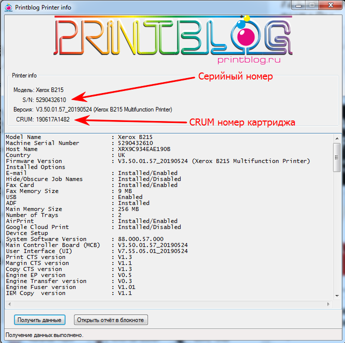
Если принтер не печатает отчет, можно узнать данные принтера через программы (Версию, Серийный номер, Crum номер). Скачать программа-1 , Скачать программа-2 .
Узнать серийный номер: Скачать программа-3 . Подробно с инструкцией тут .
Новинка. Фикс прошивка для принтеров и МФУ Pantum позволяет заправлять и использовать тонер-картриджи без замены чипа. Подробно
Если возникли проблемы — обращайтесь по email: fix@fixnu.ru или ICQ: 703238
Инструкция
Прошивка принтеров Xerox B210.
Прошивается без пайки к плате. (Debug кабель уже не нужен!).
Стандартно через USB кабель.
Вам нужно прошить принтер Xerox B210 по инструкции.
Прошивать в принудительном режиме:
1). На выключенном аппарате открыть переднюю крышку, отсоединить кабель от питания 220В (с розетки)!
Нажать и удерживать кнопку включения, подключить кабель питания, держать кнопку не отпуская до определения принтера
по usb (3 сек. примерно).
2). Перетяните мышкой файл с серийным номером FIX_NU_XXXXXXXXXX_B210_V88.000.58.000.hd на usbprns2.exe. Дождитесь перезагрузки, Принтера.
3). Удалите или заклейте чип на картридже.
Если нужно восстановить принтер Xerox B210 после неудачной прошивки для этого вам нужен Debug кабель Инструкция.
Источник
Прошивка Xerox B210 для работы без чипа картриджа
Выберите валюту вашей страны:
Мы принимаем:

- Не ошибитесь с email адресом, т.к. прошивка приходит к вам на email
- ВНИМАНИЕ! Ссылка на прошивку приходит к вам на email сразу, автоматически после оплаты.
- Все инструкции и рекомендации по прошивке читайте пожалуйста в описании НИЖЕ.
- Если остались вопросы, вы всегда можете задать их на printb@bk.ru или в чат поддержки
- Будьте внимательны, не ошибитесь в серийном номере, номере CRUM ТОНЕР картриджа (с CRUM Drum картриджа прошивка не сработает) или в выборе модели принтера, т.к. прошивка не будет работать должным образом и придется заказывать новую прошивку. БЕСПЛАТНО не переделываем!
Описание товара
Прошивка для Xerox B210 версия V85.000.58.000, V3.50.01.58_20190718, V3.50.01.54_20190403
1) Прошивка для Xerox B210 избавит принтер от необходимости использовать чип картриджа. После прошивки принтера, принтер будет всегда показывать уровень тонера 100%. Это очень выгодно!
Для отключения печати отчета конфигурации в Xerox B210 необходимо:
Сообщить о товаре в социальных сетях:
Инструкция по прошивке
Инструкция по прошивке Samsung Xerox B210
1. После оплаты заказа, вы на email получите письмо с двумя ссылками, по первой ссылке Link for download ordered fix in ZIP archive: скачиваете архив с файлами прошивки, извлекаете из архива в отдельную папку файлы прошивки.
2. Включаем принтер в принудительном режиме загрузки прошивки:
– Для этого вынимаем из принтера кабель питания 220V, сам кабель остается подключен в розетку
– Открываем переднюю крышку для доступа к картриджу
– Нажимаем и не отпускаем кнопку включения
– Подключаем к принтеру кабель питания и через 3-5 сек отпускаем кнопку включения
3. Двойным щелчком мыши запускаем файл download1.bat, который находится в папке с файлами прошивки. Появится черное окно, в котором должно пробежать очень много точек
4. Ждем несколько минут, принтер при этом на экране будет отображать процесс прошивки. Ждите перезагрузки принтера.
5. После перезагрузки принтера извлечь из картриджа чип картриджа или заклеить его скотчем. Побеспокойтесь о том, что бы не было контакта принтера с чипами картриджей, что бы не возвращаться к прошивке устройства. Чип на драм картридже также можно убрать или заклеить.
Источник
Понижение версии прошивки в Xerox B205, B210, B215 на примере B210. Пайка и прошивка NAND. Рекомендации, личный опыт.
 Про версии прошивки в Xerox B205, B210, B215, общая информация.
 Про версии прошивки в Xerox B205, B210, B215, общая информация.
На сегодняшний день сложилась ситуация с прошивками для Xerox B205, B210, B215 (и не только с ними, но пока про них), которые помогают работать этим принтерам без чипа картриджа и чипа Image unit (фотобарабан, драм) такая, что прошиваются без проблем с компьютера в пару кликов мышью только до определенной версии, а версии выше только с помощью программатора и паяльника, а также, множества тонкостей.
Если вам лень читать, можете смотреть видео, но в статье информация отличается, рекомендую также к прочтению.
Выглядит картина примерно так:
XEROX B215 прошивается с компьютера до версии V88.000.60.000, версии выше, например, V88.000.64.000 на момент публикации записи, с компьютера не прошиваются, пока только через программатор и паяльник понижаем версию и только потом прошиваем с компьютера.
Xerox B210 прошивается с компьютера до версии V88.000.58.000, версии выше, например, V88.000.60.000 на момент публикации записи, с компьютера не прошиваются, пока только через программатор и паяльник понижаем версию и только потом прошиваем с компьютера.
Xerox B205 прошивается с компьютера до версии V88.000.58.000, версии выше, например, V88.000.60.000 на момент публикации записи, с компьютера не прошиваются, пока только через программатор и паяльник понижаем версию и только потом прошиваем с компьютера.
Для общего развития, по другим моделям информация о непрошиваемых версиях на данный момент:
HP
HP Laser 107 a, r V3.82.01. 11 ( микросхема для понижения версии )
HP Laser 107 w, wr V3.82.01. 11 (микросхема для понижения версии)
HP Laser MFP 135 a, r, w, wr V3.82.01. 14 , V3.82.01. 15 (микросхема для понижения версии)
HP Laser MFP 137fnw V3.82.01. 14 (микросхема для понижения версии)
HP Color Laser 150a (nw) V3.82.01. 10
HP Color Laser 178nw V3.82.01. 11 (микросхема для понижения версии)
HP Color Laser 179fnw V3.82.01. 11 (микросхема для понижения версии)
Xerox
Xerox B205 V85.000. 60 .000 (микросхема для понижения версии)
Xerox B210 V80.000. 60 .000 (микросхема для понижения версии)
Xerox B215 V 88.000. 64 .000 (микросхема для понижения версии)
Заказать прошивку для Xerox B205, B210, B215, если у вас прошиваемые с компьютера версии прошивок или вы уже понизили версию прошивки программатором, можете у нас на сайте по ссылкам ниже:
Прошивка Xerox B205 для работы без чипа картриджа
Прошивка Xerox B210 для работы без чипа картриджа
Прошивка Xerox B215 для работы без чипа картриджа
На странице товара есть инструкции по прошивке, видеоинструкции и вся необходимая информация для успешной прошивки.
Версию прошивки принтера вы можете узнать распечатав отчет Конфигурации или с помощью программы (пароль – printblog).
Также, в случае сложностей наша служба поддержки поможет решить любую проблему. И не забывайте пользоваться накопительной скидкой.
Теперь о тех версиях прошивки, которые не прошить без программатора и паяльника.
Замечу, что эта информация будет полезна не только в случае “отучения принтера от чипов”, а и в случаях различных программных сбоев. Сбои зачастую происходят по глупости, невнимательности, наивности, жадности человека, который пытается модернизировать устройство прошивкой для работы без чипов. Не в обиду читающему, но скупой платит дважды.
Имеем мы на руках принтер любой из выше упомянутых Xerox B205, B210 или B215 с версией прошивки, которая не “прошиваемая” (назову ее так). Перед нами стоит задача прошить этот принтер модифицированной прошивкой (fix прошивка), что бы принтер работал без чипов и как итог легко и быстро заправлялся.
Прошивка у этих Xerox B205, B210 и B215 хранится в большой микросхеме памяти (NAND flash), встречается ее маркировка TC58BVG0S3HTA00.
Наша задача понизить версию прошивки принтера до версии, которую мы сможем прошить fix прошивкой с компьютера. Для этого необходимо прошить микросхему TC58BVG0S3HTA00 с помощью программатора, файлом прошивки версии, которая ниже не прошиваемой. Уточню, что это специальный файл для программатора и для микросхемы, а не прошивка, которой прошивают с компьютера. Файл этот можно скачать с принтера с помощью программатора и паяльника или заказать у нас на сайте, т.к. мы уже проделали эту работу за вас, пожалуйста:
Дамп (файл) TC58BVG0S3HTA00 для Xerox B205 версии V3.50.01.54 (понижение версии с V3.50.01.60)
Дамп (файл) TC58BVG0S3HTA00 для Xerox B210 версии V3.50.01.54 (понижение версии с V3.50.01.60)
Дамп (файл) TC58BVG0S3HTA00 для Xerox B215 версии V3.50.01.57 (понижение версии с V3.50.01.64)
Рекомендую соблюдать именно эту последовательность, что бы у принтера сохранились его серийные номера, MAC адреса и т.д., т.к. это сетевые устройства и из-за другого порядка могут быть проблемы в сети, где будут работать эти устройства, соответственно, скорее всего, будут проблемы у того хитреца, который захочет обмануть всех и сделать иначе.
В случае если нет микросхем или нечем прошить, их также можно заказать:
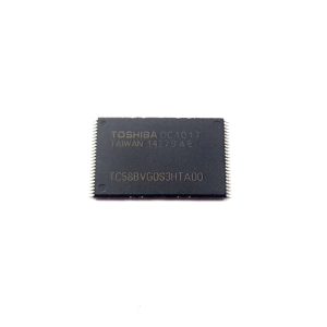
Микросхема TC58BVG0S3HTA00 для понижения версии прошивки в Xerox B205 с V88.000.60.000 до V88.000.54.000
Микросхема TC58BVG0S3HTA00 для понижения версии прошивки в Xerox B210 с V88.000.60.000 до V88.000.54.000
Микросхема TC58BVG0S3HTA00 для понижения версии прошивки в Xerox B215 с V88.000.64.000 до V88.000.57.000
Небольшой подытог после множества написанного:
- Если у принтера не прошиваемая версия прошивки, необходимо выпаять микросхему NAND flash с главной платы принтера и прошивать ее программатором, который поддерживает этот тип микросхем файлом версии прошивки для которой есть fix прошивка (Ссылки на fix прошивки и дампы (файлы для программатора и микросхем) выше в этой статье)
- После, прошивки микросхемы ИДЕАЛЬНО ее впаиваем обратно на главную плату принтера и проверяем принтер на включение. Если все включается, принтер определяется компьютером должным образом, еще и печатает, то этот этап выполнен правильно.
- Далее заказываем прошивку для работы без чипов и прошиваем принтер с компьютера, чётко следуя инструкции по прошивке.
- Если все прошло успешно, нигде не было допущено ошибок, то принтер будет работать без чипов и просто будем засыпать тонер в картриджи.
Понижение версии прошивки в Xerox B205, B210, B215 с помощью программатора в картинках с комментариями. Инструкция.
Недавно мы проделывали описанную выше операцию на Xerox B210, я сделал фотоотчет, ниже его покажу и прокомментирую. Уточню, что процесс одинаков как для B205, B210 так и для B215, отличаться будет процесс немного разборкой, fix прошивки разные и дампы для микросхем NAND тоже разные.
1. Включаем и проверяем на работоспособность устройство, если принтер исправен, выключаем его из розетки, от USB отключаем. Нажимаем кнопку Вкл на принтере, что бы разрядить блок питания.
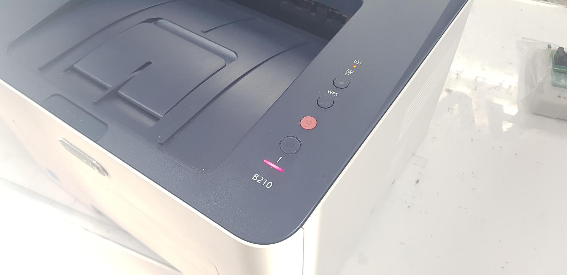
2. Снимаем боковую крышку со стороны USB порта, что бы получить доступ к главной плате принтера. Для этого открываем крышку для доступа к картриджу и вынимаем лоток для бумаги.
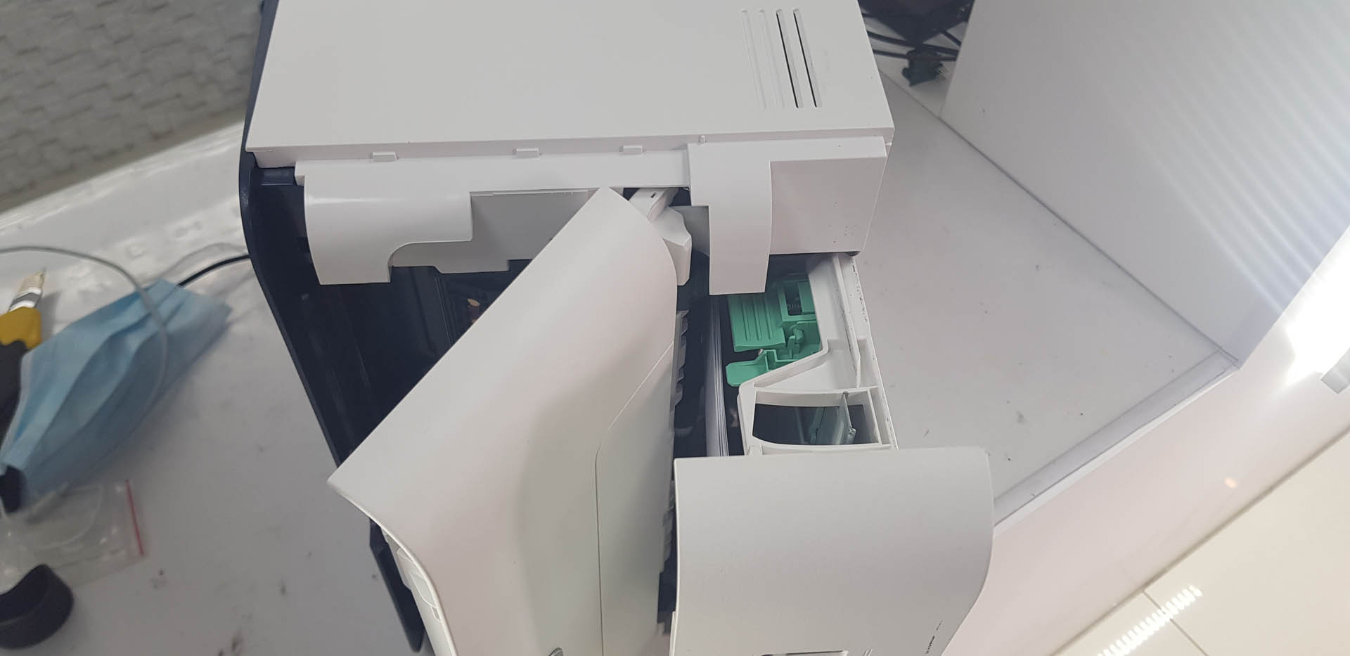
Инструментом подковыриваем возле разъема питания 220V
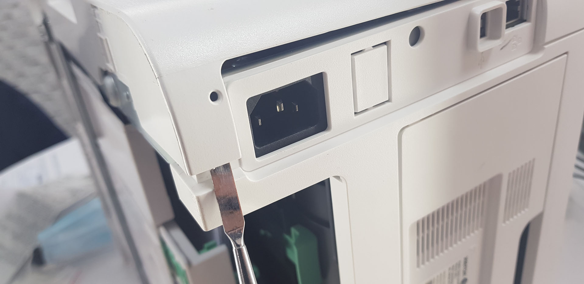
И подковыриваем возле разъема Сети
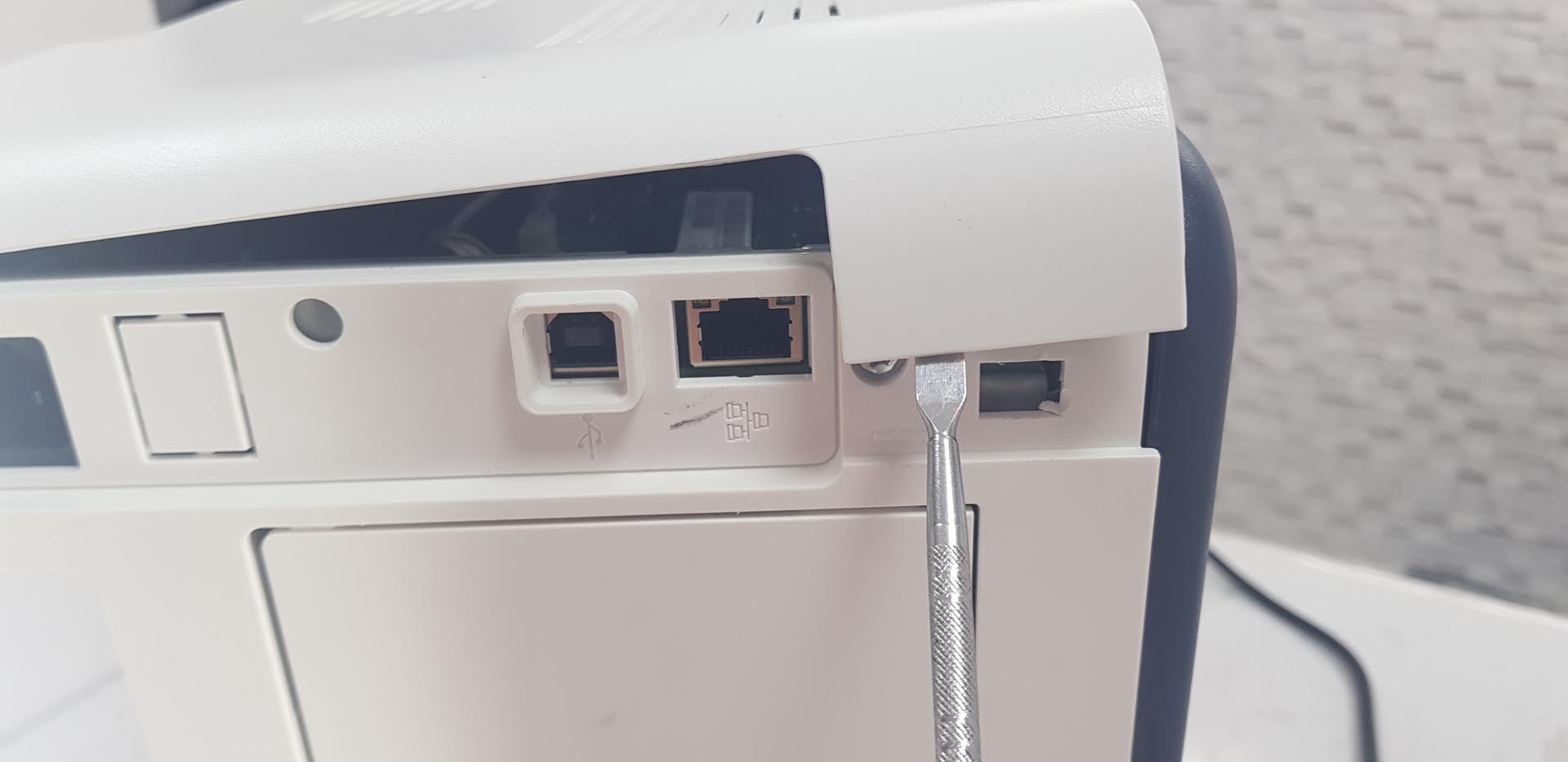
После Крышка достаточно легко снимается.
3. Появился доступ к главной плате принтера, отключаем аккуратно от нее разъемы и шлейфы, откручиваем несколько саморезов, что бы изъять плату.
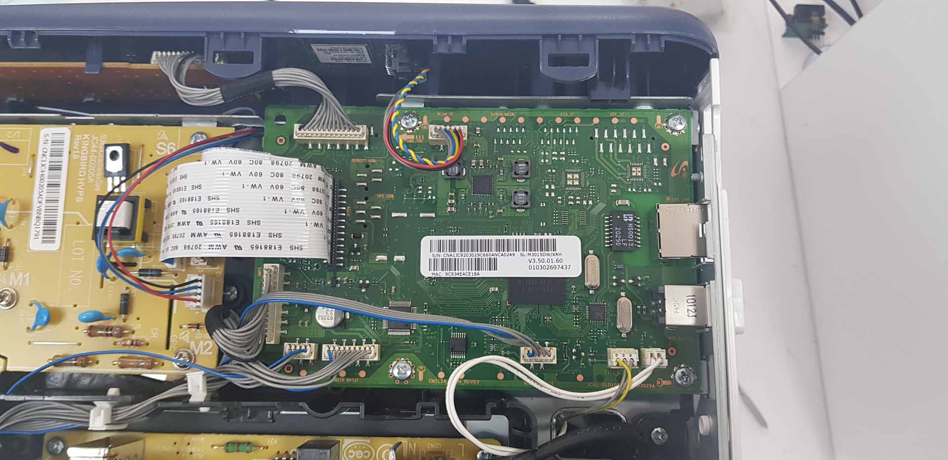
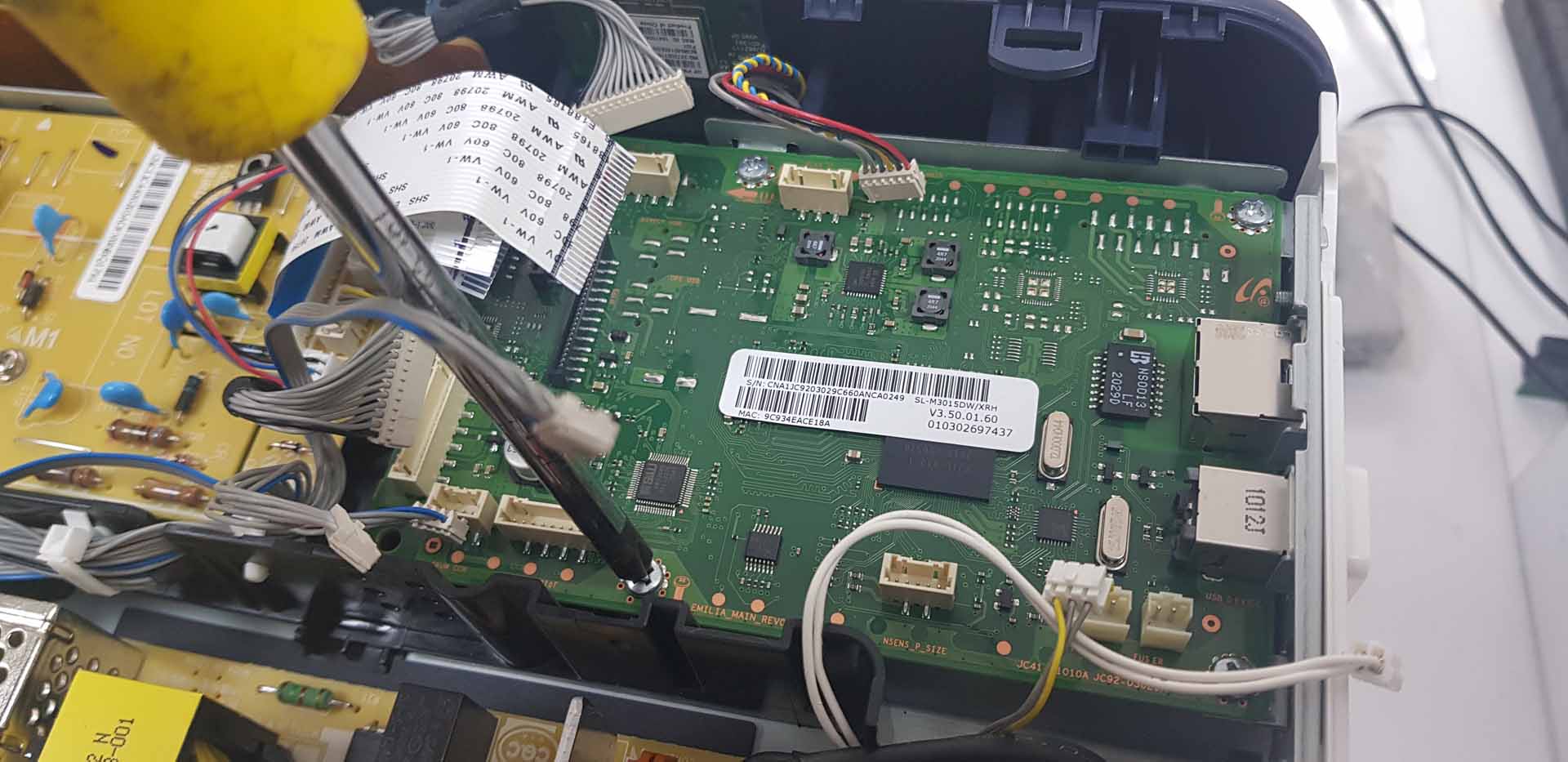
4. Вынимаем плату из принтера, переворачиваем ее и видим одну большую микросхему, которую будем паять и программировать.
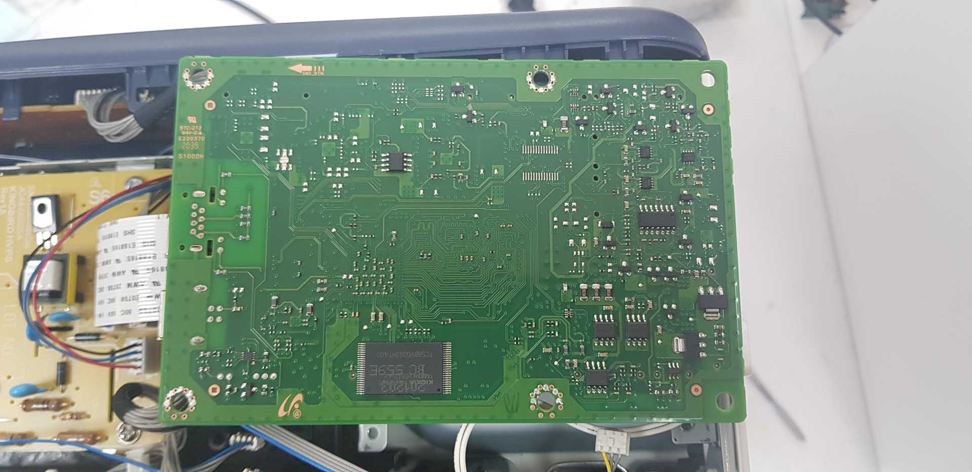
5. Выпаиваем микросхему TC58BVG0S3HTA00, на ее месте может быть микросхема с другой маркировкой или другого производителя, например, SAMSUNG. Из особенностей пайки этой микросхемы, на что я обратил внимание: припой которым она была припаяна, видимо, с высокой температурой плавления, поэтому, я с флюсом и своим припоем пропаял выводы микросхемы, что бы легче было отпаять. Отпаивал “феном” и пинцетом. Стоит это делать МЕГА осторожно, т.к. рядом много мелких SMD, которые легко отлетят и вы этого не заметите.
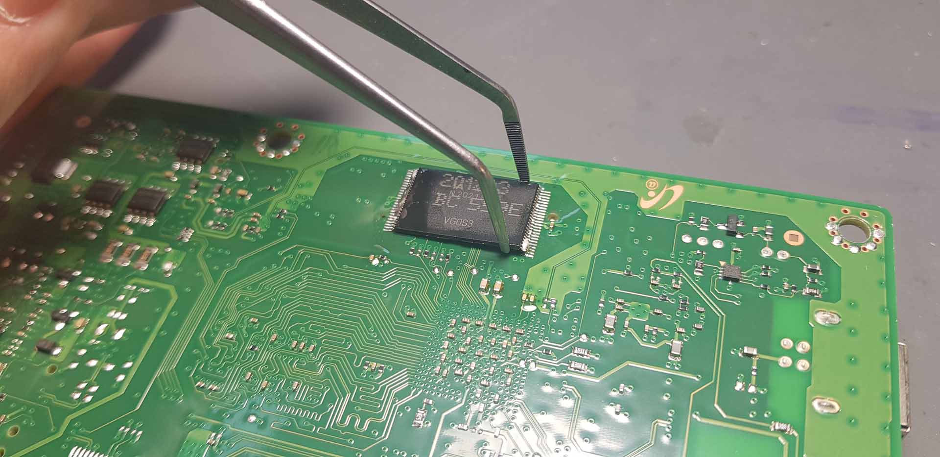
6. Выпаяв микросхему, стоит обработать ее выводы, что бы не было “коротышей” между ними, зачистить выводы лезвием или канцелярским ножом. И теперь дело за программатором.
Касаемо программатора, у многих возникнет вопрос “Каким программатором прошивать?”. Любым, который поддерживает чтение и запись NAND flash и конкретно микросхемы TC58BVG0S3HTA00. Моделей их очень много, различаются сильно по цене, поэтому выбирайте тот что вам подходит по вашим нуждам.
Допустим, программатор у вас уже есть, ссылки на файлы которыми надо прошивать еще раз дублирую и уточняю, что для каждой модели B205, B210 и B215 свой файл:
Дамп (файл) TC58BVG0S3HTA00 для Xerox B205 версии V3.50.01.54 (понижение версии с V3.50.01.60)
Дамп (файл) TC58BVG0S3HTA00 для Xerox B210 версии V3.50.01.54 (понижение версии с V3.50.01.60)
Дамп (файл) TC58BVG0S3HTA00 для Xerox B215 версии V3.50.01.57 (понижение версии с V3.50.01.64)
Микросхему считываете, сохраняете ОБЯЗАТЕЛЬНО родной дамп как резервную копию, только после стираете и записываете в нее дамп с прошиваемой версией прошивки. После записи не помешает сделать верификацию, что бы убедиться в корректности записанного. Нормальный программатор об ошибках в процессе записи должен будет сообщить.
Также у NAND flash есть отличительная особенность, это наличие битых секторов в ней, они же bad блоки, если такой попадется в месте куда будет писаться прошивка, то устройство скорее всего не запустится.
7. Микросхему прошили успешно, теперь впаиваем ее обратно в плату. Пайка должна быть идеальной и не отличаться от заводской. Просто приклеить микросхему поверх платы с помощью фена, отмыть от флюса и сделать вид красоты – это не пойдет. Впаять NAND flash, особенно ту, которая еще не паялась, это тоже своего рода искусство и крутой навык, которым обладают не все, даже те которые прогреваютпаяют чипы на материнках ПК и ноутбуков. Каждый вывод пропаивать паяльником, не жалея припоя и после не должно быть коротышей между выводами.
Припаяв идеально микросхему, собираем принтер в обратном порядке, крышку корпуса не стоит торопиться ставить, т.к. есть шанс, что придется еще раз паять, установив плату, подключив все шлейфы и разъемы в правильные места пробуем включить принтер, если включился, определился компьютером, а еще и напечатал что-то, то можно хлопать в ладоши, операция и самое сложное выполнено. Мои поздравления!
8. Заключительный этап этого шоу – это прошивка принтера правильной фикс прошивкой. Еще раз дублирую ссылки на прошивки для этих Xerox и напоминаю, что видео и текстовые инструкции находятся на странице каждой, там также подробно все разжевано, в крайнем случае наша поддержка всегда на страже и готова помочь:
Прошивка Xerox B205 для работы без чипа картриджа
Прошивка Xerox B210 для работы без чипа картриджа
Прошивка Xerox B215 для работы без чипа картриджа
Вот так будет меняться отчет принтера (1 – до манипуляций), (2 – после понижения версии), (3 – после фикс прошивки): 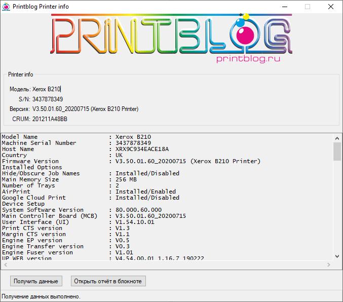
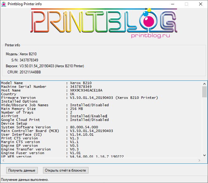
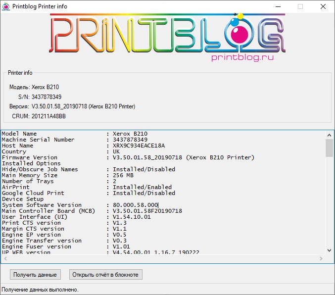
И еще одно подведение итогов:
1. Если шить, паять нечем, нет навыков или желания этим заниматься мы это можем сделать за вас. Можно нам плату прислать, мы все прошьем и отправим обратно (Россия, Казахстан, Беларусь и др. страны). Если вы в Симферополе, в Крыму, ждем вас в гости в нашем сервисном центре по ул. Старозенитная, д.9, с 9.00-18.00, +7 (978) 797-66-90 (будние)
2. Если все навыки есть, но нет программатора, без проблем отправим прошитые микросхемы для B205, B210, B215
Если возникнут вопросы, пожелания, замечания, претензии, все пишите в комментариях, обсудим. На связи!
P.S. В случае, если вы решили, что у вас нет желания или возможности возиться с пайкой и программированием микросхем, вы можете нам прислать главную плату вашего принтера, мы сами ее перепаяем, проверим и обратно вам отправим. Если вам интересна эта услуга, напишите пожалуйста нам на email ( store@printblog.ru ), обсудим детали.
Не забывайте оценить запись и поделиться ей с друзьями в социальных сетях, нажав специальные кнопки ниже.
Не забудь оставить комментарий и подписаться на наш канал Youtube 
Источник
The color of each Status LED on the control panel indicates the printer’s current status in several areas
of operation. The table below describes how to interpret each LED and its status indicators.
Status LED
Color
Printer
None
Status
Green
Red
Orange
Toner
Orange
WPS
Blue
Power
Blue
Status
Description
Off
• The printer is offline.
• The printer is in power save mode.
On
The printer is on-line and ready to be used.
Blinking
• Blinking slowly: The printer is receiving and printing
data.
• Blinking rapidly: the printer is printing data.
Blinking
A minor error has occurred and the printer is waiting for
the error to be cleared. When it clears, the printer
resumes.
On
• A cover is open. Close the cover.
• There is no paper in the tray. Load paper in the tray,
refer to
• The printer has stopped due to a major error. Reboot
the power and try the print job again. If the problem
persists, call for service.
• The Drum Cartridge has almost reached its estimated
life. It is recommended to replace the Drum Cartridge
now, refer to
Blinking
Upgrading firmware.
On
A paper jam has occurred, refer to
Blinking
Small amount of toner is left in the cartridge. Prepare a
new cartridge for replacement. You may temporarily
increase the printing quality by redistributing the toner,
refer to
On
The toner cartridge has almost reached its estimated
cartridge life. It is recommended to replace the toner
cartridge, refer to
Off
The toner cartridge is at normal capacity.
Blinking
The printer is connecting to a wireless network.
On
The printer is connected to a wireless network
Off
The printer is not connected to a wireless network.
On
The printer is in power save mode.
Off
The printer is in ready mode or the printer’s power is off.
Loading
Paper.
Replacing the Drum
Redistributing Toner.
Replacing the Toner
Xerox
Troubleshooting Overview
Cartridge.
Clearing Paper
Jams.
Cartridge.
126
B210 Printer
®
User Guide
-
Page 1
Xerox B210 ® Service Manual 702P07530 July 2019 Initial Release… -
Page 2
Xerox service documentation is intended for use by certified, product trained service per- sonnel only. Xerox does not warrant or represent that it will notify or provide to such customer any future change to this documentation. Customer performed service of equipment, or mod- ules, components or parts of such equipment may affect whether Xerox is responsible to fix machine defects under the warranty offered by Xerox with respect to such equipment. -
Page 3
Section Name Preliminary Working Document 0/0/00 No Product Name Assigned… -
Page 4: Table Of Contents
How to Use this Manual ………………..Service Safety Summary………………..Reference Symbology………………… Voltage Specifications………………… Health and Safety Incident Reporting …………….viii Regulatory Specifications………………..Translation of Warnings ………………..Tag Usage……………………Xerox® B210 Overview………………..Initial Release Introduction July 2019 Xerox® B210 Service Manual…
-
Page 5
Introduction Initial Release July 2019 Xerox® B210 Service Manual… -
Page 6: About This Manual
This section contains general information, change tag information, and general proce- Introduction dures. The Xerox® B210 Service Manual is part of the multinational documentation for the Xerox® Section 7 Wiring Data B210 Printer. It is structured in standard Xerox service documentation format. This manual is…
-
Page 7: How To Use This Manual
The machine configuration will be identified in this manual by the configuration identifier B210. The B210 is Blue Angel certified with software configuration for up to 31 ppm capability. Refer to the User Guide, Parts List and Procedures for information specific to printer configuration.
-
Page 8: Service Safety Summary
Do not use aerosol cleaners. The use of supplies that are not approved may cause poor performance and could create a hazardous condition. • Do not burn any consumables or routine maintenance items. For information on Xerox supplies recycling programs, go to www.xerox.com/gwa. Initial Release…
-
Page 9: Reference Symbology
Observe all ESD procedures to avoid component damage. CAUTION Improper operation may result in machine damage. The following reference symbols are used throughout the Xerox® B210 Service Manual. Flag • This symbol indicates a reference point into a circuit diagram from a RAP.
-
Page 10: Voltage Specifications
In this example, the red meter lead would be placed on TP21 and the black meter lead would be placed on TP33. If a second test point is not given, it is assumed that the black meter lead may be attached to the copier frame. Initial Release Introduction July 2019 Voltage Specifications Xerox® B210 Service Manual…
-
Page 11
Fund all field retrofits. Field Service Operations shall: II. Scope Preserve the Xerox product involved and the scene of the incident inclusive of any Xerox Corporation and subsidiaries worldwide. associated equipment located in the vicinity of the incident. Return any affected equipment/part(s) to the location designated by Xerox EH&S III. -
Page 12: Regulatory Specifications
® The Xerox B210 has been tested and found to comply with the limits for a Class A digital tives of the European Union as of the dates indicated: device pursuant to Part 15 of the FCC Rules. These limits are designed to provide reasonable Figure 1 CE Symbol protection against harmful interference in a commercial installation.
-
Page 13: Translation Of Warnings
GP 16. Das Modul ist sehr schwer. de las normas sobre incendios. AVISO: Utilice los procedimientos de seguridad cuando elimine el módulo. Consulte el GP 16. El módulo es pesado. Introduction Initial Release July 2019 Translation of Warnings Xerox® B210 Service Manual…
-
Page 14: Tag Usage
AVVERTENZA: Utilizzare solo materiali e componenti Xerox per avvalersi della certifica- zione di protezione. L’utilizzo di materiali e componenti non Xerox può rendere nulla la This symbol is used to show a particular part or area of a figure that has been modified by the certificazione di protezione.
-
Page 15: Xerox® B210 Overview
® Xerox B210 Overview ® Refer to the Xerox B210 User Guide, Product Configuration Section 1 for detailed descrip- tions and illustrations of Control Panel functions, machine features and options. Table 1 Product Configurations Component B210 Paper Tray — 250 Sheets…
-
Page 16
Service Call Overview ………………… Safety Precautions ………………….SCP 01 Introduction to Service Call Procedures …………SCP 02 Initial Actions…………………. SCP 03 Corrective Actions………………..SCP 04 Final Actions …………………. System/Subsystem Maintenance HFSI’s ……………………..Initial Release Service Call Procedures July 2019 Xerox® B210 Service Manual… -
Page 17
Service Call Procedures Initial Release July 2019 Xerox® B210 Service Manual… -
Page 18: Service Call Overview
Use the Repair Procedures to replace parts. Final Actions • Test the printer to verify that the problem has been corrected and that there are no additional problems. Initial Release Service Call Procedures July 2019 Service Call Overview, Xerox® B210 Service Manual…
-
Page 19: Scp 01 Introduction To Service Call Procedures
Purpose Purpose Service Call Procedures (SCP) are the guide to performing a service call on the Xerox® B210. The purpose of the Initial Actions is to help organize the service call. Customer input, machine observations and print samples are all used to gather information about the condition of the The Operator has been trained in the use of the Customer Help Information located in the system.
-
Page 20: Scp 03 Corrective Actions
Troubleshoot fault codes with the lowest chain number first If the problem is IQ related, refer to Section 3 Image Quality Entry RAP. When the primary problem is resolved, proceed to Final Actions. Initial Release Service Call Procedures July 2019 SCP 03, SCP 04 Xerox® B210 Service Manual…
-
Page 21: Hfsi’s
Customer and Service HFSI’s As with other CSE actions, these actions should be performed according to customer run requirements. Some actions may be deferred to a Xerox Initiated activity, taking into consider- ation any risks with deferring those actions. To track HFSI items, a tracking sheet is provided. The tracking sheets are located in a pocket inside the front cover of the: •…
-
Page 22
17-310 Communication Error (Main PWB to Wireless PWB) RAP ……… 2-16 17-562 Auto-Registration Process Fails to Communicate Error RAP ……2-16 17-563 Machine Fails to Communicate with Xerox Edge Server Error RAP ….2-17 17-700 / 710 BOOTP Error RAP ………………2-17 17-800 / 810 DHCP Error RAP ……………… -
Page 23
Status Indicator RAPs Initial Release July 2019 Xerox® B210 Service Manual… -
Page 24
Check for broken or defective wires or cables. • Secure the connection between the Main PWB and the HVPS. Install a new HVPS PWB, PL 4.1 Item Initial Release Status Indicator RAPs July 2019 01-150 , 02-100, 02-200 Xerox® B210 Service Manual… -
Page 25
Switch off the machine, then switch On the power. If the fault persists, install a new Main PWB, PL 1.1 Item If the fault persists, install a new Main PWB, PL 1.1 Item Status Indicator RAPs Initial Release July 2019 03-410 , 03-450 Xerox® B210 Service Manual… -
Page 26
The Main PWB is defective. • Install a new Main PWB, PL 1.1 Item If the problem persists, Install a new Main PWB, PL 1.1 Item Initial Release Status Indicator RAPs July 2019 03-900 , 04-500 Xerox® B210 Service Manual… -
Page 27
Ensure that paper is loaded in the tray. Clear any jammed sheets. Refer to Section 7: Trouble- machine. The machine could activate and cause serious personal injury when the power shooting in the Xerox® B210 User Guide for detailed instructions on clearing paper jams. is on or electrical power is supplied. -
Page 28
Remove jammed paper from Tray 1 area. Refer to Section 7: Troubleshooting, in the • Paper Drive Roll, PL 4.5 Item Xerox® B210 User Guide for detailed instructions on clearing paper jams. • Clear the paper path of any debris or obstructions. •… -
Page 29
Ensure that paper is loaded in the tray. Clear any jammed sheets. Refer to Section 7: Trouble- Clear any jammed sheets. Refer to Section 7: Troubleshooting, in the Xerox® B210 User shooting, in the Xerox® B210 User Guide for detailed instructions on clearing paper jams. -
Page 30
Initial Actions Initial Actions Clear any jammed sheets. Refer to Section 7: Troubleshooting, in the Xerox® B210 User Open the Rear Cover and remove jammed sheets from exit area. Refer to Section 7: Trouble- Guide for detailed instructions on clearing paper jams. -
Page 31
Initial Actions • Print a Supplies Information Report, Remove jammed sheets from duplex area. Refer to Section 7: Troubleshooting, in the Xerox® • Open Easy Printer Manager, check Toner Life. B210 User Guide for detailed instructions on clearing paper jams. -
Page 32
If the Toner Cartridge has reached end of life, Switch off the machine and Install a new If the Imaging Unit has reached end of life, Switch off the machine and Install a new Imag- Toner Cartridge. ing Unit. Initial Release Status Indicator RAPs July 2019 09-200 , 09-300 Xerox® B210 Service Manual 2-11… -
Page 33
Check the CRUM contact area for contamination and clean if necessary. Reinstall the Toner Cartridge. Check the connections on the HVPS for contamination. Clean as necessary. If the fault persists, install a new Toner Cartridge. Status Indicator RAPs Initial Release July 2019 09-400 , 09-500 2-12 Xerox® B210 Service Manual… -
Page 34
09-900 Imaging Unit Invalid Xerox cartridge. Initial Actions • Ensure that a genuine Xerox Imaging Unit has been installed. • Switch off, then switch on the machine. Procedure WARNING Do not perform repair activities with the power on or electrical power supplied to the machine. -
Page 35
Check the circuits and connectors for the Fuser Module. • Check the Heat Lamp for an open circuit. • Install a new Fuser Module, PL 5.1 Item Status Indicator RAPs Initial Release July 2019 10-100 , 10-200/ 300 2-14 Xerox® B210 Service Manual… -
Page 36
These faults display when the device encounters network controller problems. The faults are Procedure listed in code order together with recommended actions. Please note that the service actions Use Xerox Easy Print Manger to obtain a new IP address. are limited. From the menu, select: [Advanced Settings, Machine Settings, Network Settings, Assign Procedure IP address]. -
Page 37
Procedure The machine software has detected a communication error between the Main PWB and the Wireless PWB. Perform the steps that follow: Ensure that the Xerox SMart eSolutions settings are correct. Initial Actions Check the network cable and connection. •… -
Page 38
17-700 / 710 BOOTP Error RAP Server Error RAP The machine displays the error message “DHCP, or BOOTP, causing a machine communica- tion error. The machine failed to communicate with the Xerox Edge Server. Procedure Procedure Switch off, then switch on the machine. -
Page 39
Ensure that the 802.1X EAP Type, User name, and Password, for the Machine, Authentication Switch and Authentication Server match. Procedure Switch off, then switch on the machine. Check DHCP and network configuration. Status Indicator RAPs Initial Release July 2019 17-800 / 810 , 17-900 2-18 Xerox® B210 Service Manual… -
Page 40
The firmware upgrade aborted due to an invalid file. Initial Actions Check the USB connection. Verify that the correct firmware file is being used. Procedure Switch off, then switch on the machine. Upgrade the firmware, Initial Release Status Indicator RAPs July 2019 17-910 Xerox® B210 Service Manual 2-19… -
Page 41
Status Indicator RAPs Initial Release July 2019 17-910 2-20 Xerox® B210 Service Manual… -
Page 42
IQ7 Uneven Density RAP………………..IQ8 Background RAP …………………. IQ9 Residual Image (Ghosting) RAP …………….IQ10 Side 2 Staining ………………….. IQ11 Blank Page RAP………………… 3-10 IQ12 Partial Image Deletions RAP……………… 3-11 Initial Release Image Quality July 2019 Xerox® B210 Service Manual… -
Page 43
Image Quality Initial Release July 2019 Xerox® B210 Service Manual… -
Page 44: Image Quality Overview
Areas of the printed image are light or missing entirely IQ12 • Vertical white lines tions on limited areas of the paper. • Vertical black line or band • Stains on the page back Initial Release Image Quality July 2019 Image Quality Overview Xerox® B210 Service Manual…
-
Page 45: Iq1 Vertical Black Line And Band Rap
10, for wear or damage. The Transfer Roller is OK. Install a new Drum Cartridge if it is at end of life, refer to the Xerox® B210 User Guide, Section 6 Maintenance, General Care, for detailed instructions on how to Install a new Install a new Transfer Roll, PL 4.1 Item…
-
Page 46: Iq3 Horizontal Black Bands Rap
Switch on the power, then make a test print. The test print looks OK. Install a new Toner Cartridge. Refer to the Xerox® B210 User Guide, Section 6 Mainte- nance, General Care, for detailed instructions on how to Install a new Toner Cartridge.
-
Page 47: Iq5 Low Image Density Rap
• If the image is Black, install a new HVPS PWB, PL 4.1 Item 2, switch on the power, then make a test print. Figure 1 Light Image Image Quality Initial Release July 2019 IQ5, IQ6 Xerox® B210 Service Manual…
-
Page 48: Iq7 Uneven Density Rap
Print density is uneven between the left and right portion of the printed image, Figure NOTE: Refer to the Xerox® B210 User Guide, Section 6 Maintenance, General Care, for Initial Actions detailed instructions on how to install new Toner Cartridges. Refer to Tabe 5 in Section 6, Product Specifications, for toner cartridge specifications.
-
Page 49: Iq8 Background Rap
Switch on the power, then make a test print. The test print looks OK. Install a new HVPS PWB, PL 4.1 Item Perform 04, Final Actions. Figure 1 Uneven Density Figure 1 Background Image Quality Initial Release July 2019 IQ7, IQ8 Xerox® B210 Service Manual…
-
Page 50: Iq9 Residual Image (Ghosting) Rap
PL 5.1 Item If fault persists, install new components in the following order: Refer to the Xerox® B210 User Guide, Section 6 Maintenance, General Care, for detailed instructions on how to Install a new Toner Cartridge or Drum Cartridge. Drum Cartridge…
-
Page 51: Iq11 Blank Page Rap
Switch on the power, then make a test print. The problem continues. Perform SCP 04, Final Actions. Install a new Drum Cartridge, refer to the Xerox® B210 User Guide, Section 6 Maintenance, General Care, for detailed instructions on how to Install a new Drum Cartridge. The problem continues.
-
Page 52: Iq12 Partial Image Deletions Rap
10, for the following: • Wear or damage. • The left and right tension springs for damage. • Verify all parts are installed correctly. Figure 1 Image Deletions Initial Release Image Quality July 2019 IQ12 Xerox® B210 Service Manual 3-11…
-
Page 53
Image Quality Initial Release July 2019 IQ12 3-12 Xerox® B210 Service Manual… -
Page 54
REP 4.16 Feed Idler Gear………………..4-39 REP 4.17 Main Drive Unit ………………..4-40 REP 4.18 Pick Up Assembly ………………. 4-41 REP 5.1 Fuser Module………………..4-43 REP 6.1 Retard Roll Assembly ………………4-45 Initial Release Repairs — Adjustments July 2019 Xerox® B210 Service Manual… -
Page 55
Repairs — Adjustments Initial Release July 2019 Xerox® B210 Service Manual… -
Page 56: Rep 1.1 Main Pwb
After installing a new Main PWB, the following steps MUST be performed to write the machine serial number to the new Main PWB: Reconnect the power cord, then power on the machine. Connect the PWS to the printer via USB connection. Initial Release Repairs — Adjustments July 2019 REP 1.1 Xerox® B210 Service Manual…
-
Page 57: Rep 1.2 Wifi Pwb
(device serial number). Inform the customer to reset SA Password as desired. NOTE: After performing a Memory Clear, inform the customer that they will need to re-estab- lish their Wireless or Ethernet connection. Repairs — Adjustments Initial Release July 2019 REP 1.1, REP 1.2 Xerox® B210 Service Manual…
-
Page 58
Release the hook, then remove the SUB PWB (WiFi), Figure Figure 2 Disconnect FFCs and harnesses Figure 4 SUB PWB removal Release two hooks, then remove the Top Cover, Figure Figure 3 Top Cover removal Initial Release Repairs — Adjustments July 2019 REP 1.2 Xerox® B210 Service Manual… -
Page 59: Rep 2.1 Front Cover
Remove the Left and Right Side Covers, 2.2. Disconnect the wire harness to the Front Cover, Figure Connector Figure 1 Front Cover P/J Connector Figure 5 SUB PWB replacement Repairs — Adjustments Initial Release July 2019 REP 1.2, REP 2.1 Xerox® B210 Service Manual…
-
Page 60
NOTE: Remove the Tag Matrix from the old front cover, then place on the new front cover, Figure Figure 4 Tag Matrix on new Front Cover Assembly Initial Release Repairs — Adjustments July 2019 REP 2.1 Xerox® B210 Service Manual… -
Page 61: Rep 2.2 Left And Right Side Covers
Release (pull) the center front latch hook. Release the top latch hooks then the bottom latch hooks. Release the rear latch hook, and remove the cover. Repairs — Adjustments Initial Release July 2019 REP 2.1, REP 2.2 Xerox® B210 Service Manual…
-
Page 62: Rep 2.3 Rear Cover
Screws Figure 2 Plastic Latches Replacement Replacement is the reverse of the removal procedure. Drive Gear Figure 1 Rear Cover Screws and Data Plate Label Initial Release Repairs — Adjustments July 2019 REP 2.2, REP 2.3 Xerox® B210 Service Manual…
-
Page 63: Rep 2.4 Manual Feed Cover
Cover and install it onto the new Rear Cover, Figure old cover, then installation of the Tag Matrix on the new Manual Feed Cover, Figure Repairs — Adjustments Initial Release July 2019 REP 2.3, REP 2.4 4-10 Xerox® B210 Service Manual…
-
Page 64: Rep 3.1 Control Panel Pwb
Figure 1 Main PWB Connectors to Disconnect Figure 1 Control Panel PWB (Underside of Top Covers) Replacement Replacement is the reverse of the removal procedure. Initial Release Repairs — Adjustments July 2019 REP 3.1, REP 3.2 Xerox® B210 Service Manual 4-11…
-
Page 65
Figure Screws Latch Hooks Figure 3 Top Cover Latch Hooks Figure 2 Top Cover Screws (Front View) Replacement Replacement is the reverse of the removal procedure. Repairs — Adjustments Initial Release July 2019 REP 3.2 4-12 Xerox® B210 Service Manual… -
Page 66: Rep 4.1 Hvps (High Voltage Power Supply)
Switch off the machine, then disconnect the power cord. Remove the Right Side Cover, 2.2. Figure 1 HVPS PWB Replacement Replacement is the reverse of the removal procedure. Initial Release Repairs — Adjustments July 2019 REP 4.1 Xerox® B210 Service Manual 4-13…
-
Page 67: Rep 4.2 Lvps (Low Voltage Power Supply)
NOTE: Tapered plastic screws and round machine screws are used to hold the pwb to the frame. Make sure that the plastic screws go into plastic components and machine screws go into the metal frame. Repairs — Adjustments Initial Release July 2019 REP 4.2 4-14 Xerox® B210 Service Manual…
-
Page 68: Rep 4.3 Feed And Registration Clutches / Paper Feed Pwb
Figure 1 Transfer Roll Retainer Clip Registration Clutch Feed Clutch Figure 1 Feed and Registration Clutches / Paper Feed PWB Replacement Replacement is the reverse of the removal procedure. Initial Release Repairs — Adjustments July 2019 REP 4.3, REP 4.4 Xerox® B210 Service Manual 4-15…
-
Page 69: Rep 4.5 Lsu And Cables
NOTE: The Flat Cable may be adhered to the LSU. Detach it from the LSU and reinstall it on the new LSU in the same location. Repairs — Adjustments Initial Release July 2019 REP 4.4, REP 4.5 4-16 Xerox® B210 Service Manual…
-
Page 70: Rep 4.6 Duplex Assembly
Release Tabs Figure 2 LSU Removal (Top View) Replacement Replacement is the reverse of the removal procedure. Figure 1 Duplex Assembly Release Tabs (Bottom View) Initial Release Repairs — Adjustments July 2019 REP 4.5, REP 4.6 Xerox® B210 Service Manual 4-17…
-
Page 71: Rep 4.7 Output Tray Full Sensor
Remove five screws, then move the Main PWB out of the way, Figure Main PWB Pivot Hole Figure 2 Duplex Assembly Pivots (Rear View) Figure 1 Main PWB Repairs — Adjustments Initial Release July 2019 REP 4.6, REP 4.7 4-18 Xerox® B210 Service Manual…
-
Page 72: Rep 4.8 Exit Roll And Bushings
NOTE: When installing the Main PWB, make sure the ground screw with large head is installed in the correct location. Driver Gear Figure 1 Exit Roll and Bushing (Top View) Replacement Replacement is the reverse of the removal procedure. Initial Release Repairs — Adjustments July 2019 REP 4.7, REP 4.8 Xerox® B210 Service Manual 4-19…
-
Page 73: Rep 4.9 Registration Roll
Remove the Feed and Registration Clutch Drive Gears, Figure Clutch Drive Gears Shaft Bushings Clutch Bushings Figure 2 Drive Gears and Bushings Figure 1 Feed and Registration Clutch Drive Gears Repairs — Adjustments Initial Release July 2019 REP 4.9 4-20 Xerox® B210 Service Manual…
-
Page 74
11. On the bottom of the printer, disconnect the drive motor connector, then remove the ground screw, Figure Connector Screw Figure 5 Drive Motor Connector & Screw (Bottom View) Initial Release Repairs — Adjustments July 2019 REP 4.9 Xerox® B210 Service Manual 4-21… -
Page 75
Disconnect seven connectors, three FFCs, remove five screws, then remove the Main PWB. HVPS PWB Main PWB Figure 7 LSU Left Side Screws Screw LVPS PWB Figure 6 PWB Removal Figure 8 LSU Right Side Screws Repairs — Adjustments Initial Release July 2019 REP 4.9 4-22 Xerox® B210 Service Manual… -
Page 76
15. Remove two screws from the right frame securing the Exit Sensor Plate, Figure tact guide, then remove the guides, Figure Screws Screws Figure 10 Exit Sensor Plate Screws Figure 9 Wire Guides and HV Contact Guide Initial Release Repairs — Adjustments July 2019 REP 4.9 Xerox® B210 Service Manual 4-23… -
Page 77
17. Remove three screws securing the Middle Frame and Pickup Frame Base on the left- Middle Frame on the right-side, Figure side, Figure Frame Screws Exit Screws Screws Figure 11 Right Frame Screws Removal Figure 12 Left Frame Screw Removal Repairs — Adjustments Initial Release July 2019 REP 4.9 4-24 Xerox® B210 Service Manual… -
Page 78
Pivot Plate, Collar, Registration Roll Pivot Gear, and Registration Drive Gear Figure 14 Registration Roll Drive Gear and Bushing Figure 13 Registration Roll Drive Pivot Gears Initial Release Repairs — Adjustments July 2019 REP 4.9 Xerox® B210 Service Manual 4-25… -
Page 79
22. Remove the Bushing and E-ring from the Registration Roll, Figure E-ring Bushing Snap Ring Figure 17 Feed and Registration Drive Gears Figure 16 Registration Roll Repairs — Adjustments Initial Release July 2019 REP 4.9 4-26 Xerox® B210 Service Manual… -
Page 80: Rep 4.10 Feed And Registration Sensors Pwb And Actuators
Set the printer on the Rear Cover (Front of printer facing up). Remove two screws, then remove the Bottom Bar, Figure Screws Figure 18 Front Cover Support Arm Placement Figure 1 Bottom Bar (Bottom View) Initial Release Repairs — Adjustments July 2019 REP 4.9, REP 4.10 Xerox® B210 Service Manual 4-27…
-
Page 81
Note the location of the Spring in the frame cutout for reinstallation, Figure Spring Cutouts Latch Figure 5 Actuator Spring Cutouts (Bottom View) Figure 3 Feed and Registration Sensors PWB (Bottom View) Repairs — Adjustments Initial Release July 2019 REP 4.10 4-28 Xerox® B210 Service Manual… -
Page 82: Rep 4.11 Manual Paper Tray
Remove the Top Cover, 3.2. Remove two screws securing the bottom of the Manual Paper Tray, Figure Screws Figure 1 Manual Paper Tray Bottom Screws (Bottom View) Initial Release Repairs — Adjustments July 2019 REP 4.10, REP 4.11 Xerox® B210 Service Manual 4-29…
-
Page 83: Rep 4.12 Exit Sensor
Figure 2 Manual Paper Tray Top Screws (Top View) Replacement Replacement is the reverse of the removal procedure. Figure 1 Exit Sensor Plate Latch Release (Bottom View) Repairs — Adjustments Initial Release July 2019 REP 4.11, REP 4.12 4-30 Xerox® B210 Service Manual…
-
Page 84: Rep 4.13 Paper Drive Roll
Figure 2 Exit Sensor Removal (Rear View) Replacement Replacement is the reverse of the removal procedure. Figure 1 Feed and Registration Clutch Drive Gears Initial Release Repairs — Adjustments July 2019 REP 4.12, REP 4.13 Xerox® B210 Service Manual 4-31…
-
Page 85
Remove two screws, then remove the Registration Pinch Rolls and Paper Guide Brack- ets, Figure Clutch Bushing Feed Shaft Bushings Figure 2 Feeder Drives Screws Figure 4 Registration Pinch Rolls and Paper Guide Brackets Repairs — Adjustments Initial Release July 2019 REP 4.13 4-32 Xerox® B210 Service Manual… -
Page 86
Install the Feed Assembly upper half, install the two Feed Assembly bottom screws, then route the wires through the frame. Refer to, Figure 6 in the removal procedure. Drive Roll Lower Half Figure 6 Feed Assembly Lower Half Initial Release Repairs — Adjustments July 2019 REP 4.13 Xerox® B210 Service Manual 4-33… -
Page 87: Rep 4.14 Paper Feed Roll Assembly
Figure 2 Paper Feed Roll Assembly removal (Bottom View) Remove the Retard Rolls from the assembly, Figure Figure 1 Removing the Bottom Bar (Bottom View) Figure 3 Retard Rolls removal Repairs — Adjustments Initial Release July 2019 REP 4.14 4-34 Xerox® B210 Service Manual…
-
Page 88: Rep 4.15 Drive Motor
Remove the Feed and Registration Clutch Drive Gears, Figure Bushing Flat Clutch Drive Gears Figure 1 Feed and Registration Clutch Drive Gears Figure 4 Bushing Flat (Bottom View) Initial Release Repairs — Adjustments July 2019 REP 4.14, REP 4.15 Xerox® B210 Service Manual 4-35…
-
Page 89
Exit Drive Gears Snap Ring Step 8a Clutch Bushings Step 10 Feed & Registration Drive Gears Figure 2 Drive Gears and Bushings Figure 3 Frame Screw Removal Repairs — Adjustments Initial Release July 2019 REP 4.15 4-36 Xerox® B210 Service Manual… -
Page 90
Figure 11. Remove four screws, then remove the Drive Motor, Figure Drive Motor Step 3b Step 3a Figure 5 Drive Motor Figure 6 Frame Screw Installation Initial Release Repairs — Adjustments July 2019 REP 4.15 Xerox® B210 Service Manual 4-37… -
Page 91
Figure Figure 8 Front Cover Support Arm Placement Snap Ring Figure 7 Feed and Registration Drive Gears Install the remaining components in the reverse of removal. Repairs — Adjustments Initial Release July 2019 REP 4.15 4-38 Xerox® B210 Service Manual… -
Page 92: Rep 4.16 Feed Idler Gear
Remove the Feeder Clutch and Drive Gear. Feed Idler Gear Figure 2 Feed Idler Gear Replacement Replacement is the reverse of the removal procedure. Feed Clutch Figure 1 Feed Clutch Removal Initial Release Repairs — Adjustments July 2019 REP 4.16 Xerox® B210 Service Manual 4-39…
-
Page 93: Rep 4.17 Main Drive Unit
NOTE: Make sure the two tabs on the locking lever are inside the frame cutouts before moving the fuser drive locking lever to the lock position. Repairs — Adjustments Initial Release July 2019 REP 4.17 4-40 Xerox® B210 Service Manual…
-
Page 94: Rep 4.18 Pick Up Assembly
Install the remaining components in the reverse of the removal procedure. Figure 1 One-way pickup frame and bushing removal Remove the pickup guide from the upper pickup guide, Figure Figure 2 Pickup guide removal Initial Release Repairs — Adjustments July 2019 REP 4.17, REP 4.18 Xerox® B210 Service Manual 4-41…
-
Page 95
Remove the actuator holder and TS-spring from the width and paper actuators, Figure Figure 4 Washer and bushing removal Figure 6 Actuator holder and TS-spring removal Repairs — Adjustments Initial Release July 2019 REP 4.18 4-42 Xerox® B210 Service Manual… -
Page 96: Rep 5.1 Fuser Module
Switch off the machine, then disconnect the power cord. Remove the following covers: Remove the Left and Right Side Covers, 2.2. Remove the Rear Cover, 2.3. Initial Release Repairs — Adjustments July 2019 REP 4.18, REP 5.1 Xerox® B210 Service Manual 4-43…
-
Page 97
NOTE: Tapered plastic screws and round machine screws are used to hold the fuser to the frame. Make sure that the plastic screws go into plastic components and machine screws go into the metal frame. Repairs — Adjustments Initial Release July 2019 REP 5.1 4-44 Xerox® B210 Service Manual… -
Page 98: Rep 6.1 Retard Roll Assembly
Rotate the Retard Roll Holder up and remove it from the Paper Tray, Figure Slide Out Figure 3 Retard Roll Removal Replacement Replacement is the reverse of the removal procedure. Initial Release Repairs — Adjustments July 2019 REP 6.1 Xerox® B210 Service Manual 4-45…
-
Page 99
NOTE: Make sure the two springs on the Retard Roll Holder are correctly positioned on the holes, Figure Springs Figure 4 Springs Located in Holes Repairs — Adjustments Initial Release July 2019 REP 6.1 4-46 Xerox® B210 Service Manual… -
Page 100
PL 5.1 Fuser PL 5.1 Fuser……………………5-13 PL 5.2 Lower Fuser PL 5.2 Lower Fuser………………….5-14 PL 6.1 Paper Tray PL 6.1 Paper Tray ………………….5-15 Part Number Index ………………..5-16 Initial Release Parts List July 2019 Xerox® B210 Service Manual… -
Page 101
Parts List Initial Release July 2019 Xerox® B210 Service Manual… -
Page 102: 1.1 Main Overview
– Paper Tray 6.1) – Top Cover 3.1) – Rear Cover 2.1) – Coupling B Lever – Frame 140N63856 Main PWB (REP 1.1) 140N63862 Wifi PWB (REP 1.2) Initial Release Parts List July 2019 PL 1.1 Xerox® B210 Service Manual…
-
Page 103: 2.1 Covers
Spring – Front Cover Latch Sensor – CRUM PWB – CRUM Contacts – Front Cover – Manual Feed Cover (REP 2.4) – Front Harness Cover – CRUM Harness Parts List Initial Release July 2019 PL 2.1 Xerox® B210 Service Manual…
-
Page 104: 3.1 Top Cover
Paper Stacker – Bin Full Sensor Actuator – Spring – Exit Cover 140N63723 Control Panel PWB (REP 3.1) – Key Holder – Holder 002N03351 Top Cover Assembly (REP 3.2) Initial Release Parts List July 2019 PL 3.1 Xerox® B210 Service Manual…
-
Page 105: 4.1 Frame
Right Main Frame 062N00292 (REP 4.5) – Duplex (REP 4.6) 130N01574 Exit Sensor – Registration Roll Pivot Gear – Registration Roll Drive Gear – Pivot Plate – Collar Parts List Initial Release July 2019 PL 4.1 Xerox® B210 Service Manual…
-
Page 106: 4.2 Duplex Assembly
Pulley – Exit Gear – Flat Rubber Belt – Feed Roller – Duplex Base Frame – Duplex Latch – Align Lever 022N02815 Duplex Assembly — (A4/Letter) (REP 4.6) Initial Release Parts List July 2019 PL 4.2 Xerox® B210 Service Manual…
-
Page 107: 4.3 Exit Frame
– Decurler Roller – Exit Shaft – Rubber Exit Dup – Inner Exit Roller – Outer Exit Roller – Exit Roll Holder – Spring – Exit Frame Assembly Parts List Initial Release July 2019 PL 4.3 Xerox® B210 Service Manual…
-
Page 108: 4.4 Paper Path
Registration Idle Roller – Manual Left Adjust – Manual Right Adjust – Lower Paper Guide – Pinion Gear – Roller Cover – – Idle Roller – Spring – Sub-Holder Idle Initial Release Parts List July 2019 PL 4.4 Xerox® B210 Service Manual…
-
Page 109: 4.5 Base Pick Up
(REP 4.18) – Spring TS (REP 4.18) – Actuator — Width (REP 4.18) – Actuator — Paper (REP 4.18) – Feed Sensor PWB (REP 4.18) – Washer Parts List Initial Release July 2019 PL 4.5 5-10 Xerox® B210 Service Manual…
-
Page 110: 4.6 Left Main Frame
Fuser Locking Lever – Hub Clutch Gear – Feed Gear – Feed Gear 2 – Cam Coupler – Coupling Lever 007N01842 Main Drive Unit (REP 4.17) – Harness Cover Initial Release Parts List July 2019 PL 4.6 Xerox® B210 Service Manual 5-11…
-
Page 111: 4.7 Right Main Frame
– CST Rear Guide – Lower Guide – Foot – Right Frame – Cable Clamp – LVPS Cover – Developer Right Guide – Spring – Ground Clip Parts List Initial Release July 2019 PL 4.7 5-12 Xerox® B210 Service Manual…
-
Page 112: 5.1 Fuser
Rear Guide – Exit Idle Roller – Spring – Actuator Holder – Exit Sensor Actuator 126N00430 Fuser Module (110V) (REP 5.1) – 126N00431 Fuser Module (220V) (REP 5.1) Initial Release Parts List July 2019 PL 5.1 Xerox® B210 Service Manual 5-13…
-
Page 113: 5.2 Lower Fuser
Gear – Roller – Spring – Bushing – Left Jam Lever Link – Antistatic Brush – Jam Lever – Right Jam Lever Link – Lower Fuser Assembly Parts List Initial Release July 2019 PL 5.2 5-14 Xerox® B210 Service Manual…
-
Page 114: 6.1 Paper Tray
– Right Paper Guide – Paper Tray Handle – Paper Tray Rear Guide – Paper Tray Frame – Paper Tray Handle – Paper Indicator 050N00700 Paper Tray Initial Release Parts List July 2019 PL 6.1 Xerox® B210 Service Manual 5-15…
-
Page 115: Part Number Index
PL 4.6 130N01574 PL 4.5 130N01574 PL 4.1 130N01574 PL 4.3 130N01759 PL 4.4 130N01760 PL 4.5 140N63723 PL 3.1 140N63856 PL 1.1 140N63862 PL 1.1 Parts List Initial Release July 2019 Part Number Index 5-16 Xerox® B210 Service Manual…
-
Page 116
Initial Release Parts List July 2019 Part Number Index Xerox® B210 Service Manual 5-17… -
Page 117
Initial Release Parts List July 2019 Part Number Index Xerox® B210 Service Manual 5-18… -
Page 118
Parts List Initial Release July 2019 Part Number Index 5-19 Xerox® B210 Service Manual… -
Page 119
Parts List Initial Release July 2019 Part Number Index 5-20 Xerox® B210 Service Manual… -
Page 120
GP 7 Usage of the Electrostatic Discharge (ESD) Field Service Kit ……. 6-12 GP 8 Memory Clear ………………….6-13 GP 9 USB Serial Number Writing Tool …………….6-13 Change Tags Tags/MODs ……………………6-15 Initial Release General Procedures — Information July 2019 Xerox® B210 Service Manual… -
Page 121
General Procedures — Information Initial Release July 2019 Xerox® B210 Service Manual… -
Page 122: General Information
General Information System Overview The Xerox® B210 printer produces high quality prints from electronic documents with speeds This section provides illustrations of the following systems: of up to 31 ppm and output resolution of up to 1200 x 1200 dpi.
-
Page 123
The following diagrams display the path that the paper follows during the printing process. The figures below illustrates the mechanical parts of the printer. Figure 1 Paper Path Figure 2 System Layout General Procedures — Information Initial Release July 2019 System Overview Xerox® B210 Service Manual… -
Page 124
The Scanner Unit receives image data from the HVPS PWB and scans the surface of the pho- cess. toreceptor drum (OPC) with a laser to create a latent image. Figure 3 Print Process Figure 4 Laser Scanner Unit Initial Release General Procedures — Information July 2019 System Overview Xerox® B210 Service Manual… -
Page 125
Drum Cartridge (OPC), Fuser, Pick-up, Registration, Feed and Exit Rollers. Figure 5 Drive Gears and Clutches Figure 6 Separated Toner System General Procedures — Information Initial Release July 2019 System Overview Xerox® B210 Service Manual… -
Page 126: Product Specifications
Executive, Oficio, Folio, ISO B5, JIS B5 Media Types Plain, Light-weight, Heavy-weight, Cardstock, Recy- cled, Archive, Bond Media Weight 16 to 58 lb (60 to 220 gsm) Sensing Initial Release General Procedures — Information July 2019 Product Specifications Xerox® B210 Service Manual…
-
Page 127
Imaging Unit 0.84 lbs. (0.38 kg) When replacing a Toner/Print Cartridge, check model number and consumables code. Refer to the Xerox® B210 User Guide for information regarding ordering consumables. Table 6 Reliability and Service Item Specification Printing Volume (SET AMPV) -
Page 128: Gp 1 Diagnostics Entry And Exit
GP 1 Diagnostics Entry and Exit GP 2 Machine Reports Not applicable for the B210. No Diagnostics are available. Purpose This procedure is used to access and print machine reports. The information in the machine reports may be useful for troubleshooting problems.
-
Page 129: Gp 3 Machine Firmware Version
From the Control Panel: To change settings using the CentreWare Internet Services (CWIS). Connect to the Xerox® B210 to an Ethernet or WiFi connection. Press the red <Cancel> button for 4 seconds. The machine will print a Configuration Open Easy Print Manager and select [Advanced Settings > Device Settings > Link to Report listing the firmware version under the [Device Setup] heading.
-
Page 130: Gp 5 Altitude Adjustment
0 — 1000 M Normal 0 — 3,280 ft. Connect the printer using the USB cable. Open Easy Printer Manager. Select: [Device Settings, System, Altitude Adjustment]. Initial Release General Procedures — Information July 2019 GP 4, GP 5 Xerox® B210 Service Manual 6-11…
-
Page 131: Gp 6 Firmware Upgrade
GP 7 Usage of the Electrostatic Discharge (ESD) Field Service Kit Purpose The following procedure is to be used for upgrading the firmware of the B210 single function Purpose printer. The purpose of the Electrostatic Discharge (ESD) Field Service Kit is to preserve the inherent reliability and quality of sensitive electronic components handled by the service representative.
-
Page 132: Gp 8 Memory Clear
NOTE: After performing a Memory Clear, inform the customer that they will need to re-estab- lish their Wireless or Ethernet connection. Click <Write Serial>. NOTE: The Xerox® B210 uses the following tool only: • USB_Serial_V1.02.exe — to write the machine number to the Main PWB.
-
Page 133
General Procedures — Information Initial Release July 2019 GP 8 , GP 9 6-14 Xerox® B210 Service Manual… -
Page 134: Change Tags
Optional: install as a customer option or a field engineering decision. Situational: install as the situation demands. Manufacturing: cannot be installed in the field. Refurbishing only. Initial Release General Procedures — Information July 2019 Tags Xerox® B210 Service Manual 6-15…
-
Page 135
General Procedures — Information Initial Release July 2019 Tags 6-16 Xerox® B210 Service Manual… -
Page 136
7 BSD BSD Block Schematic Diagrams ………………BSD 1……………………..BSD 2……………………..Initial Release July 2019 Xerox® B210 Service Manual… -
Page 137
Initial Release July 2019 Xerox® B210 Service Manual… -
Page 138
BSD Block Schematic Diagrams Xerox® WorkCentre® B210 Multifunction Printer This document contains wiring and mechanical power data for the Xerox® WorkCentre® B210 Printers. These block schematic diagrams are supplemental to the diagnostic and troubleshooting infor- mation found in the Xerox® WorkCentre® B210 Service Manual. -
Page 139
BSD 1 1.1 — Main/Power/Electrical/Drive/Fuser/Networking/LSU/CRUM Figure 1 BSD 1.1 — Main/ADF/Power/Electrical/Drive/Fuser/Networking/LSU/CRUM Initial Release July 2019 Xerox® B210 Service Manual… -
Page 140
BSD 2 2.1 Printer OPE Figure 1 BSD 2.1 Printer OPE Initial Release July 2019 Xerox® B210 Service Manual… -
Page 141
Initial Release July 2019 Xerox® B210 Service Manual… -
Page 142
©2014 Xerox Corporation. All rights reserved. Xerox® and the sphere of connectivity design are trademarks of Xerox Corporation in the US and/or other countries..